I. INTRODUCTION
Grain refinement was an effective method to improve both the strength and toughness of metals and their alloys. In recent years, new technologies, such as equal-channel angular pressing (ECAP) and continuous extrusion forming (CONFORM), have been used to prepare fine-grained materials and ultrafine grain materials. Reference Mukai, Kawazoe and Higashi1–Reference Kim, Ko, Shin and Lee4 Both ECAP and CONFORM technologies could make severe plastic deformation to the alloys, Reference Li, Wei, Pei and Zhao5,Reference Manninen, Katajarinne and Ramsay6 leading to fine-grain microstructures and good performance of the alloys. However, compared with ECAP, CONFORM was much simpler, more energy-efficient, and environmentally friendly, and it has been widely developed and applied in mass production in industry. Reference Zhao, Song and Yun7–Reference Zhang, Yan and Li10
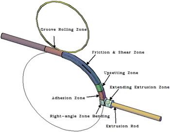
Cu–Mg alloy with high strength and conductivity was an ideal material for contact wires of high-speed electrical railway. Reference Zhao, Liu, Liu, Chen, Ma, Li and He11 Zhu et al. investigated the effect of ECAP and cold deformation on the properties of Cu–Mg alloy, Reference Zhu, Ma, Jiang, Li, Song, Yang, Yuan and Chen12 and found that server deformation could significantly improve their mechanical property of the alloy while maintaining its good electrical conductivity, due to the ultrafine and elongated grains formed during deformation. The deformation zone of continuous extrusion workpiece could be divided into the following ones according to their microstructures: groove rolling zone, friction & shear zone, upsetting zone, adhesion zone, right-angle bending zone, and extending extrusion zone (shown in Fig. 1). Grain size could not be changed basically in groove rolling zone and friction & shear zone. The microstructure of the alloy in upsetting zone, adhesion zone, right-angle bending zone, and extending extrusion zone could be changed obviously, which would have a significant influence on the final microstructure and properties of the alloy. Reference Wang, Yun, Li, Fan and Song13 The microstructure evolution of pure copper during continuous extrusion process has been studied by dynamic mathematical model and integrating finite element analysis. Reference Wang14 It was reported that dynamic recrystallization occurred in extruded Cu–Mg alloys, but the recrystallization grain did not grow up during continuous extrusion. Reference Cai and Liu15 Nevertheless, little work has been done on grain refinement mechanism and recrystallization process during continuous extrusion in mass production. Investigations on the effect of grain refinement and recrystallization on the properties of the alloy could be expected to guide the industrial production in continuous extrusion field.
Deformation zones in continuous extrusion process.

II. MATERIALS AND EXPERIMENT
A. Materials preparation
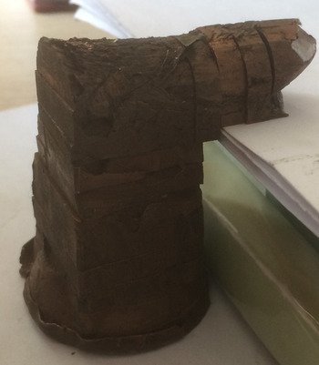
Mass production of the Cu–0.2Mg alloy was carried out on an industrialized production line. Cu–0.2Mg (wt%) alloy was firstly melted by an industrial induction furnace. The raw materials were commercially cathode copper (99.95%) and pure magnesium (99.95%). The casted rod with a diameter of Φ20 mm was drawn through upward continuous casting. The rod was water-sealing extruded continuously into bar using TLJ500 continuous extruder manufactured by Dalian Jiaotong University, China. For the CONFORM process, the feedstock with a diameter of 20 mm was extruded into a rod of 25 mm in diameter. The wheel speed is 3.5 rpm and the preheating temperature is 723 K. The samples cut from the extrusion block with an average interval of 5 mm were shown in Fig. 2.
Photo of continuously extruded copper block after division.

B. Experimental method
HB-3000 Brinell hardness tester (Huayin Test Intsrument company, Laizhou, China) was used to measure the hardness of samples, with the pressure head diameter of 2.5 mm and test load of 62.5 kg. Hardness was measured along upsetting zone, adhesion zone, right-angle bending zone, extending extrusion zone, and extrusion rod with an average interval of 5 mm. Each area was measured for five times and the average value was taken.
The microstructure of the alloy was observed with FEI TECNAL G2 transmission electron microscopy (TEM, FEI company, Portland, OR), with the operation voltage of 200 kV. The sample was thinned by jet electro polishing in 30 vol% nitric acid and 70% methanol solution at about −30 °C. The Sirion 200 scanning electron microscopy (PHILIPS company, Amsterdam, Holland) equipped with the electron backscatter diffraction (EBSD) was used to analyze the microstructure evolution.
III. RESULTS
A. Mechanical properties
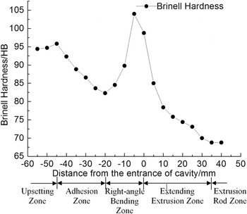
The hardness variation along with the deformation direction of extruded Cu–Mg alloy was shown in Fig. 3. Hardness in upsetting zone increased from 94.4 HB to 95.8 HB and then decreased rapidly to 82.3 HB in adhesion zone. In right-angle bending zone, it increased sharply till reached the maximum, with value of 104.0 HB, and then decreased. Hardness in extending extrusion zone decreased rapidly at first and then decreased gently. The final extruded rod had a hardness of 68.8 HB.
Hardness distribution during continuous extrusion process.

B. EBSD characterization
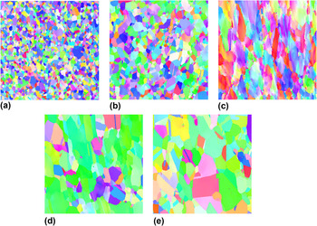
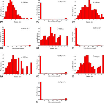
To investigate the microstructure evolution in continuous extrusion process, EBSD was used to characterize the morphology, size, and orientation distribution of grain in upsetting zone, adhesion zone, right-angle bending zone, extending extrusion zone and extrusion rod. Figure 4 showed the EBSD maps of extruded Cu–0.2Mg alloy and Fig. 5 showed the grain size and misorientation angle distributions obtained by EBSD. Figure 4(a) was the typical EBSD map of upsetting zone. Recrystallization occurred in upsetting zone and the original structure was replaced by recrystallization structure. Most of the grain boundaries were clear. The average size of the grains in upsetting zone was about 2.19 μm [Fig. 5(a)] and the proportion of low-angle grains (<10°) was 72.5% [Fig. 5(b)]. Figure 4(b) was the typical EBSD map of adhesion zone. Recrystallization grains coarsened, and annealing twins were found in this area. The average grain size increased to about 3.83 μm [Fig. 5(c)], and the proportion of low-angle grains (<10°) increased to 82.4% [Fig. 5(d)]. Figure 4(c) was the typical EBSD map of right-angle bending zone. Large shear deformation occurred as the alloy passed through the right-angle bending zone, and grains rotated with the pressure axis under shear force. Large amount of shear deformation bands and deformed structures formed in matrix. The average size of grain was about 8.27 μm [Fig. 5(e)] and the proportion of low-angle grains (<10°) was 91.3% [Fig. 5(f)]. Figure 4(d) was the typical EBSD map of extending extrusion zone. Grain boundaries were distinctly appeared and grain morphology was generally slender-like. Annealing twins and recrystallization grains appeared, while substructures with small misorientation still existed in some grains with high-angle grain boundary. The distribution of grain was heterogeneous and the sizes of most of grains were about 3–9 μm, with small amount of grains larger than 10 μm. Upon statistics, the average grain size was 8.57 μm [Fig. 5(g)], misorientation between grains was little, and the proportion of low-angle grains was 83.0% [Fig. 5(h)]. Compared with the sample in right-angle bending zone, the grain size had little change, but the volume fraction of the grain boundary with orientation difference of 60° increased to 6.4%. Reference Field, Eames and Lillo16–Reference Gong, Wen and Wu19 Figure 4(e) was the typical EBSD map of sample cut from the extrusion rod. Grains were equiaxed-like and grain boundaries were relatively straight. Large amount of annealing twins were found in the sample and the distribution of grain sizes became much heterogeneous. The average grain size was 8.62 μm [Fig. 5(i)]. Low-angle grain boundaries further decreased, with the relative proportion of 85.6%. The proportion of twins had no change, which was still 6.4%. The grain size and misorientation between grains were similar with those in extending extrusion zone. After continuous extrusion, the rod was water-cooled as it got out of the mold cavity, which had obviously effect on the growth of recrystallization grains.
EBSD maps of Cu–0.2Mg alloy during CONFORM. (a) Upsetting zone; (b) adhesion zone; (c) right-angle bending zone; (d) extending extrusion zone; (e) extrusion rod.

Grain size and misorientation angle distributions obtained by EBSD. (a, b) Upsetting zone; (c, d) adhesion zone; (e, f) right-angle bending zone; (g, h) extending extrusion zone; (i, j) extrusion rod.

C. Microstructures
1. Microstructures in upsetting zone
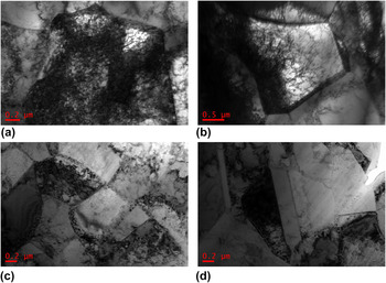
Upsetting deformation occurred as the Cu–0.2Mg alloy rod passed through upsetting zone. The typical TEM of the sample in this zone is shown in Fig. 6. Grains were stretched along with shear deformation direction and lots of slip bands appeared. Dislocation density increased sharply, and jogs interacted with solute atoms during dislocation motion, leading to the formation of a dislocation tangle zone with disordering network structure. The dislocation distribution was very heterogeneous. From Fig. 6(a), it could be seen that the grain was divided into several subgrains by dense dislocation walls (DDWs). DDWs were almost in parallel and parallel DDWs formed microbands (MBs). The grain was divided into cell block with S-shape [Fig. 6(b)], Reference Yu20 or small plane cell band (SPC) with flat-shape [Fig. 6(c)]. The distribution of dislocations situated in MBs was heterogeneous [Fig. 6(c)], which was attributed to the heterogeneous deformation. The grain boundary moved toward the matrix with high dislocation density, suggesting a strain induced movement and resulting in the formation of smooth boundary of grain. Reference Gorelik21
Bright field TEM images of the sample in upsetting zone. (a) DDWs; (b) cell block with S-shape; (c) SPC with flat-shape; (d) grain boundary migration.

2. Microstructures in adhesion zone
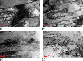
The polygonization occurred in adhesion zone because of the deformation heat. Size of dislocation cell was small, which was about 500 nm. Cell wall was thick and dislocation tangle was serious. Dislocation density inside the cells was different due to the inconsistency of deformation. The distribution of dislocation was inhomogeneous [Fig. 7(a)]. Figures 7(b) and 7(c) showed that the recrystallization nucleation took place at the original grain and the bowed boundary grew into the local region with the highest stored energy. The nucleation mechanism of the subgrain coalescence also occurred [Fig. 7(c)]. The recrystallization microstructures appeared in adhesion zone of the alloy and annealing twins also took place in the zone [Fig. 7(d)].
Bright field TEM images of the sample in adhesion zone. (a) inhomogeneous dislocations; (b, c) recrystallization structures; (d) annealing twins.

3. Microstructures in right-angle bending zone
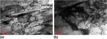
The sample was shear-deformed as they passed through the right-angle bending zone, where the lamellar structure appeared. Misorientation between the band-like substructures was small (proportion of low-angle grain boundary was 91.3%). A great deal of dislocation formed by the heavy shear-deformation arrayed paralleled to the direction of shear-one, resulting in the formation of lamellar structure [Fig. 8(a)]. The width of the lamellar was about 100 nm, which was also the width of dislocation cell [Fig. 8(b)].
Bright field TEM images of the sample in right-angle bending zone. (a) lamellar structure; (b) dislocation cell.

4. Microstructures in extending extrusion zone
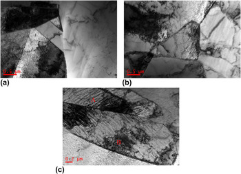
Microstructures in extending extrusion zone were complicated. The recrystallization grain boundary was straight, and annealing twins appeared. These may be attributed to the low stacking fault energy of face-centered cubic Cu–Mg alloy, so the stacking sequence of {111} plane situated in the grain boundary intersection was easy to be changed by the thermal stress, resulting in the formation of stacking fault. Essentially, the stacking fault was equivalent to a twin with one atom thickness. As interfacial energy of coherent twin boundary was smaller than that of high-angle grain boundary, the stacking fault would be stable and became nucleus of the twin, and it grew with the movement of high-angle grain boundaries. Reference Wang, Brisset, Helbert, Solas, Drouelle, Mathon and Baudin22 Typical dislocation cell structures also existed [Fig. 9(b)]. Band-like structures were also processed. The dislocation was hard to tangle and arrayed along with a certain direction [Fig. 9(c) “A”], while the recrystallization nucleation occurred by boundary migration, as well as subgrain coalescence [Fig. 9(c) “B”]. As a result, the deformation in this zone was inhomogeneous.
Bright field TEM images of the sample in extending extrusion zone. (a) recrystallization grain; (b) dislocation cell structures; (c) band-like structures (where “A” show dislocations, and “B” show recrystallization grains).

5. Microstructures in extrusion rod
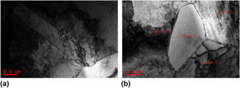
TEM observation showed that microstructures in extrusion rod were different from others. On one hand, annealing twins appeared in matrix [Fig. 10(a)]; on the other hand, nucleation and growth of recrystal grains also occurred. As a nucleus of recrystallization, boundary of grain “A” bowed out to the grain “B” and “C” with high storing energy. And grain “D” had already become a complete recrystal grain in equilibrium. Triple grain boundary junction (grain “A”, “C”, and “D”) was close to 120° [Fig. 10(b)]. Reference Humphreys and Hatherly23
Bright field TEM images of the sample in extrusion rod. (a) annealing twins; (b) recrystallization structures.

IV. DISCUSSION
A. Performance evolution
It was found that hardness changed a little during upsetting process, suggesting that two conflicting processes, strain hardening & polygonization and partial recrystallization softening existed in this zone at the same time. Stain hardening was attributed to the dislocation pile-up generated by the increase of dislocation density and dislocation interaction during deformation. Softening process was caused by the decrease of dislocation density and dislocation redistribution to form more stable configuration actuated by deformation thermal. From the results of EBSD and TEM, original grain boundaries no longer existed and the average size of subgrains was 2.19 μm in the zone. Matrix in adhesion zone still had heavy storing energy, and the polygonization occurred under the actuating of deformation heat; recrystal grain grew, annealing twins appeared, and average size of subgrains increased to 3.83 μm. Influenced by polygonization and grain growth, hardness of the sample in this zone decreased. In right-angle bending zone, original isometric recrystal grains were substituted by the large amount of banded microstructures. Banded microstructure boundaries were of highly dense dislocation and cell structures formed in the band because of the dislocation tangle. Subgrain size was between 200 and 500 nm and the hardness of the sample increased due to the fine grain strengthening. After the billet entered into the extending extrusion zone, expanded deformation of the billet did not occur until the billet entered into the horn mouth zone. As deformation and recrystallization occurred together, some recrystal grains deformed again, which led to strain hardening. This could reasonably explain that in extending extrusion zone, hardness firstly decreased rapidly and then decreased gently.
B. Grain refinement
It could be concluded that the fine grain of the alloy fabricated by continuous extrusion formed during deformation in upsetting zone and shear deformation in right-angle bending zone.
Mainly mechanism for grain refinement in upsetting zone was the division of dislocation wall mechanism. Reference Valiev and Langdon24–Reference Iwahashi, Horita, Nemoto and Langdon26 The Cu–0.2Mg copper rod was upset as it passed the upsetting zone. Multiple slip system was activated with the deformation, and large amount of slip bands occurred in matrix. DDW formed by the dislocation tangle [Fig. 6(a)]. Because of the deformation heat, the matrix could be divided into two or more parallel band-like structure, which presented double wall one, and flat-like one (SPC) [Fig. 6(c)]. Dislocation walls (DWs) formed due to the movement of dislocation, which divided the deformed matrix into fine subgrains.
The isometric recrystal microstructures formed in adhesion zone had still low-angle grain boundaries (proportion of low-angle grains was 82.4%). Under shear deformation in right-angle bending zone, long cell structures formed. Misorientations between these cell substructures were low (proportion of low-angle grains was 91.3%). As the MBs constantly overlaid, the spread band-like deformation zone formed. Band-like deformation microstructures were generally called shear bands. Although shear bands were divided by low-angle grain boundaries and crushed into many subgrains [Fig. 8(b)], grains were not further refined, due to the in situ recrystallization process.
C. Recrystallization
During the continuous extrusion process, continuous recrystallization (in situ recrystallization) and discontinuous recrystallization (initial recrystallization) occurred. Discontinuous recrystallization included nucleation and growth process. When discontinuous recrystallization was completed, grains were isometric, such as the recrystallize microstructures in upsetting zone and adhesion zone. Due to the water cooling effect, recrystallization happened in extending extrusion zone, which was mainly continuous dynamic recrystallization, and grains were still at the elongated state.
Discontinuous recrystallization nucleated in the serious distortion zone with high storing energy. In upsetting zone and adhesion zone, dislocations re-distributed into much stable configuration upon the deformation heat. High- and low-angle boundary formed through the dislocation rearrangement. The polygonization could be regarded as the initial stage of discontinuous recrystallization. After polygonization, recrystallization occurred, and the recrystallize mechanism was the subgrain boundary migration and the subgrain coalescence. Because of the large shear deformation, equiaxed grains elongated and banded structure formed. The recrystallizaton nucleation in the banded structure would affect the motion of grain boundary, promoting the formation of recrystallizaton grains.
According to EBSD data, grain size in extending extrusion zone and right-angle bending zone was almost the same, however, a part of high-angle grain boundaries in extending extrusion zone were flat, indicating that extremely strong recovery process occurred in this zone. During this recovery process, low-angle grain boundaries (subgrains) formed. Although long-range movement of high-angle grain boundaries did not occur, the in situ recrystallization occurred by subgrain coalescence in this stage, which was called continuous recrystallization.
For the growth of recrystallize grains, grain boundary tension played a key role on boundary migration and grain shape. To maintain the minimum grain boundary energy and equal grain boundary tension, each angle of triple grain boundary junction was close to 120° in the extruded alloy. The grain boundary was convex as grain boundary number was less than 6.
V. CONCLUSIONS
-
(1) Performance of Cu–0.2Mg alloy continuously changed during continuous extrusion process. Work-hardening, recovery and recrystallization softening coexisted in upsetting zone. Hardness increased slowly due to the synthetic action; it decreased sharply in upsetting zone due to the synthetic action of polygonization, recrystallization and grain growth; it approached the maximum in right-angle bending zone because of shear deformation; and in extending extrusion zone hardness decreased at first and then decreased gently.
-
(2) In upsetting zone and adhesion zone, the grain refinement formed by the division of DW; in right-angle bending zone, shear banded microstructures formed by the shear deformation.
-
(3) During continuous extrusion process, continuous recrystallization (in situ recrystallization) and discontinuous recrystallization (initial recrystallization) took place. The mechanism of nucleation was boundary migration and subgrain coalescence. These would provide guidance for the design of optimal microstructure of Cu–Mg alloy for the target applications through the continuous extrusion technology.
ACKNOWLEDGMENTS
The authors are pleased to acknowledge the financial supply supported by the project supported by the National Natural Science Foundation of China (51271203), the Nonferrous Metals Science Foundation of HNG-CSU (YSZN2013CL06).