Introduction
The communication system with high data transmission rate requires a wide operation bandwidth. Besides, a high-efficiency communication system will not only reduce the consumption of energy resource but also enhance the stability of the system itself. Power amplifier (PA) is one of the most important modules in communication system, and the quality of communication system is directly affected by the performance of PA. Thus, the broadband and high-efficiency PA is the research focus of communication engineers.
Harmonic components are critical to the linearity and efficiency of PAs [Reference Kim and Choi1]. Harmonic tuning technology is adopted in [Reference Cai, Che and Xue2, Reference Cai, Che, Ma and Gu3]; although the efficiency has been improved drastically, nevertheless, accurate harmonic tuning in a wide frequency band is very difficult. The bandwidth of PA is effectively broadened with continuous modes [Reference Latha and Rawat4–Reference Chang, Roblin, Hahn, Martinez-Lopez, Liang and Rawat8]; since the harmonic and fundamental components are simultaneously matched by one network, the design freedom is limited, and the efficiency is relatively low. In addition, filter structures are also used in the matching networks of PA to realize high efficiency [Reference Zhou, Perez-Cisneros, Langborn, Eriksson and Fager9–Reference Su, Yu, Tang and Liu11].
The SRR structure with good filter characteristics and compact size is applied in many circuit designs [Reference Baena, Bonache, Martín, Sillero, Falcone, Lopetegi, Laso, Garcia-Garcia, Gil, Portillo and Sorolla12–Reference Zuffanelli, Zamora, Aguila, Paredes, Martín and Bonache14]. The LC equivalent circuit of SRR is analyzed in [Reference Baena, Bonache, Martín, Sillero, Falcone, Lopetegi, Laso, Garcia-Garcia, Gil, Portillo and Sorolla12], but its scattering parameters have not been studied and cannot be directly applied in microwave circuit design. The scattering parameters of unloaded SRR are analyzed in [Reference Fan, Liang and Wu13]; however, the findings are not suitable for loaded SRR structure design. Since the SRR can be built with microstrip line structure, its impedance characteristics can be derived and applied to the matching network of PA.
This paper presents a design strategy for high-efficiency broadband PA, which uses SRR as the second harmonic output matching network (SHOMN). Due to the limited influence of the third harmonic on the performance of PA, only the fundamental and second harmonic components are considered. The fundamental matching and second harmonic matching are carried out, respectively, by two networks, which can improve the matching accuracy in a broadband. In addition, the even–odd mode analysis is introduced to derive the impedance transformation equations of SRR to realize accurate matching, and the deduction is also useful for the future research of SRR technology.
This paper is organized as follows. The section “Analysis of SRR for PA SHOMN design” presents the analysis for SRR characteristics and the feasibility of acting as SHOMN and deduces the impedance transformation equations. The section “High-efficiency broadband PA design” introduces the processes of high-efficiency broadband PA design. The section “Implementation and measurement of PA” shows the implemented PA and measured results and the section “Conclusion” draws a conclusion.
Analysis of SRR for PA SHOMN design
Frequency response characteristics of SRR
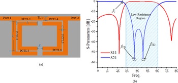
Figure 1 presents the model of proposed two-ports SRR and its frequency response. The structure of SRR is composed of two rectangular rings, the outer ring has one splitand the inner has two, and it can be equivalent to six parallel coupling transmission line (PCTL) cells labeled as PCTL1–PCTL6 and one series transmission line labeled as TL1. The label l 1 is an equivalent length of PCTL1, PCTL3, PCTL4, and PCTL6, and it is the average of the length of PCTL1 at outer ring part and the length at inner ring part. Similarity, l 2 is an equivalent length of PCTL2 and PCTL6; g is the length of TL1 or the width of split; c is the line width; and c 1 is the width of the gap. Because of the same line widths and gap widths, all the cells have the same odd-mode characteristic impedance and even-mode characteristic impedance. The frequency response exhibits that SRR has a band-stop characteristic, and two transmission zeros f TZ1 and f TZ2 are generated, and f C is the cutoff frequency. The real part of input impedance of SRR is near zero in the stopband, and the second harmonic components for high-efficiency PA is located at the edge of the Smith chart. Therefore, theoretically, SRR can act as SHOMN of the high-efficiency PA.
The model of the proposed SRR (a) with simulated S-parameters (b).

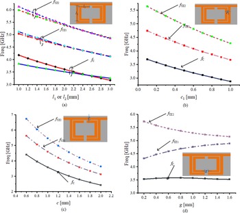
Influence of dimensional parameters on the frequency response of SRR is summarized in Fig. 2. It is worth noticing that adjusting l 1, l 2, c, and c 1 have similar effect on the positions of f TZ1, f TZ2, and f C; thus, more degree of freedom for adjusting input impedance of SRR can be obtained. However, the width g of the split has great impact on the bandwidth of stopband; higher value of g introduces narrower stopband, which influences the bandwidth of the second harmonic matching.
f TZ1, f TZ2 and f C values against dimensional parameters (a) l 1 and l 2, (b) c, (c) c 1, and (d) g.

Equation deduction for SRR impedance transformation
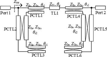
In order to speculate the input impedance trajectories of SRR for second harmonic matching and obtain the impedances at SRR output plane for subsequent fundamental matching, the impedance transformation characteristics of SRR need to be further analyzed. Figure 3 shows the equivalent schematic of SRR in Fig. 1; Z 0e and Z 0o are even-mode and odd-mode characteristic impedances of the parallel coupling transmission line cells, respectively. For simplifying the computation, the electrical length is introduced to replace the physical length in the following derivation, such as θ r1 = 2πl 1/λ (λ is the waveguide wavelength) replaces the physical length l 1, θ r2 replaces l 2, and θ g replaces g.
Schematic of the proposed two-ports SRR.

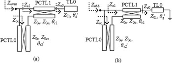
Due to the symmetrical structure, SRR can be analyzed by the even–odd-mode analysis. Even-mode and odd-mode circuits of SRR are described in Fig. 4; both of two circuits can be regarded as PCTL1 shunts with coupling transmission line PCTL0 with electrical length of θ′ r2, where θ′ r2 = θ r2 + θ r1, and series with the transmission line TL0 with characteristic impedance of Z 01 and electrical length of θ′ g, where θ′ g = θ g/2. The terminal of TL0 is open in the even mode and is short in the odd mode.
Even-mode circuit (a) and odd-mode circuit (b) of SRR.

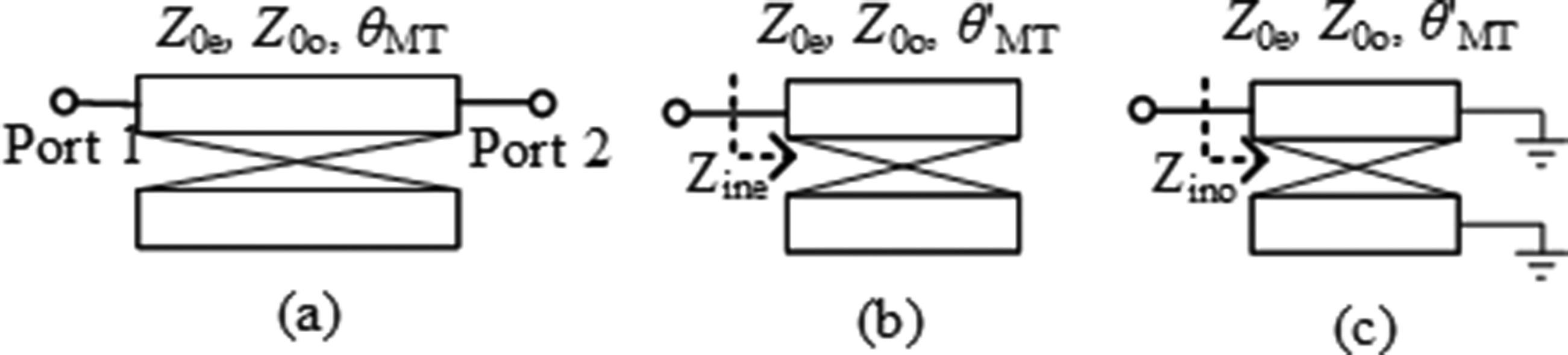
Before the analysis for SRR, the impedance characteristic for the parallel coupling transmission line cells should be deduced. Figure 5 shows a two-port cell with its even-mode circuit and odd-mode circuit. The even-mode input impedance Z ine and odd-mode input impedance Z ino can be obtained from (1) and (2), respectively.
 \begin{equation}{Z_{{\textrm{ine}}}} = - {\textrm{j}}\sqrt {{Z_{{\textrm{0e}}}}{Z_{{\textrm{0o}}}}} \cot {\theta^{\prime}_{{\textrm{MT}}}},\end{equation}
 \begin{equation}{Z_{{\textrm{ino}}}} = {\textrm{j}}\sqrt {{Z_{{\textrm{0e}}}}{Z_{{\textrm{0o}}}}} \tan {\theta^{\prime}_{{\textrm{MT}}}},\end{equation}
The topology of circuit cell (a) with even-mode (b) and odd-mode circuits (c).

where θ′ MT is half of the electrical length θ MT of the cell.
The impedance matrix of the cell is expressed as
 \begin{equation}\left[ {\textbf{Z}} \right] = {1 \over 2}\left[ \begin{matrix} {{Z_{{\textrm{ine}}}} + {Z_{{\textrm{ino}}}}} & {{Z_{{\textrm{ine}}}} - {Z_{{\textrm{ino}}}}} \\ {{Z_{{\textrm{ine}}}} - {Z_{{\textrm{ino}}}}} & {{Z_{{\textrm{ine}}}} + {Z_{{\textrm{ino}}}}} \end{matrix} \right].\end{equation}
The input impedance Z L of cell load is introduced to transform the impedance matrix to the scattering matrix
 \begin{equation}\left[ {\textbf{S}} \right] = \left[ {\begin{matrix} {{{{Z_{{\textrm{ine}}}}{Z_{{\textrm{ino}}}} - {Z_{\textrm{L}}}^2} \over {\left( {{Z_{{\textrm{ine}}}} + {Z_{\textrm{L}}}} \right)\left( {{Z_{{\textrm{ino}}}} + {Z_{\textrm{L}}}} \right)}}} & {{{{Z_{\textrm{L}}}\left( {{Z_{{\textrm{ine}}}} - {Z_{{\textrm{ino}}}}} \right)} \over {\left( {{Z_{{\textrm{ine}}}} + {Z_{\textrm{L}}}} \right)\left( {{Z_{{\textrm{ino}}}} + {Z_{\textrm{L}}}} \right)}}} \\ {{{{Z_{\textrm{L}}}\left( {{Z_{{\textrm{ine}}}} - {Z_{{\textrm{ino}}}}} \right)} \over {\left( {{Z_{{\textrm{ine}}}} + {Z_{\textrm{L}}}} \right)\left( {{Z_{{\textrm{ino}}}} + {Z_{\textrm{L}}}} \right)}}} & {{{{Z_{{\textrm{ine}}}}{Z_{{\textrm{ino}}}} - {Z_{\textrm{L}}}^2} \over {\left( {{Z_{{\textrm{ine}}}} + {Z_{\textrm{L}}}} \right)\left( {{Z_{{\textrm{ino}}}} + {Z_{\textrm{L}}}} \right)}}} \end{matrix} } \right].\end{equation}
With reference to [Reference Wang, He, You, Shi, Peng and Li10], the input impedance of the cell can be calculated as
 \begin{equation}{Z_{{\textrm{in1}}}} = {{{Z_{\textrm{L}}}\left( {{Z_{{\textrm{ine}}}} + {Z_{{\textrm{ino}}}}} \right) + 2{Z_{{\textrm{ine}}}}{Z_{{\textrm{ino}}}}} \over {2{Z_{\textrm{L}}} + {Z_{{\textrm{ine}}}} + {Z_{{\textrm{ino}}}}}}.\end{equation}
As for the even-mode circuit in Fig. 4(a), the input impedance of TL0 is
 \begin{equation}{Z_{{\textrm{e0}}}} = - {\textrm{j}}{Z_{01}}\cot {\theta^{\prime}_{\textrm{g}}}.\end{equation}
According to (5), the input impedance of PCTL1 is
 \begin{equation}{Z_{{\textrm{e1}}}} = {\textrm{j}}{{2{Z_{{\textrm{01}}}}\sqrt {{Z_{{\textrm{0o}}}}{Z_{{\textrm{0e}}}}} \cot {{\theta^{\prime}}_{\textrm{g}}}\left( {\tan {{\theta^{\prime}}_{{\textrm{r1}}}} - \cot {{\theta^{\prime}}_{{\textrm{r1}}}}} \right) + 2{Z_{{\textrm{0e}}}}{Z_{{\textrm{0e}}}}} \over {2{Z_{{\textrm{01}}}}\cot {{\theta^{\prime}}_{\textrm{g}}} - \sqrt {{Z_{{\textrm{0o}}}}{Z_{{\textrm{0e}}}}} \left( {\tan {{\theta^{\prime}}_{{\textrm{r1}}}} - \cot {{\theta^{\prime}}_{{\textrm{r1}}}}} \right)}},\end{equation}
where θ′ r1 = θ r1/2.
For PCTL0 with open terminal, its input impedance is
 \begin{equation}{Z_{{\textrm{oc}}}} = - {\textrm{j}}\sqrt {{Z_{{\textrm{0e}}}}{Z_{{\textrm{0o}}}}} \cot {\theta^{\prime}_{{\textrm{r2}}}}.\end{equation}
Thus, the even-mode input impedance of SRR can be calculated as
 \begin{equation}{Z_{{\textrm{even}}}} = {{{Z_{{\textrm{e1}}}}{Z_{{\textrm{oc}}}}} \over {{Z_{{\textrm{e1}}}} + {Z_{\textrm{o}}}_{\textrm{c}}}}.\end{equation}
In Fig. 4(b), the input impedance of TL0 is
 \begin{equation}{Z_{{\textrm{o0}}}} = {\textrm{j}}{Z_{{\textrm{01}}}}\tan {\theta^{\prime}_{\textrm{g}}}.\end{equation}
Moreover, the input impedance of PCTL1 is
 \begin{equation}{Z_{{\textrm{o1}}}} = {\textrm{j}}{{2{Z_{01}}\sqrt {{Z_{{\textrm{0o}}}}{Z_{{\textrm{0e}}}}} \tan {{\theta^{\prime}}_{\textrm{g}}}\left( {\tan {{\theta^{\prime}}_{{\textrm{r1}}}} - \cot {{\theta^{\prime}}_{{\textrm{r1}}}}} \right) - 2{Z_{{\textrm{0o}}}}{Z_{{\textrm{0e}}}}} \over {2{Z_{{\textrm{01}}}}\tan {{\theta^{\prime}}_{\textrm{g}}} + \sqrt {{Z_{{\textrm{0o}}}}{Z_{0{\textrm{e}}}}} \left( {\tan {{\theta^{\prime}}_{{\textrm{r1}}}} - \cot {{\theta^{\prime}}_{{\textrm{r1}}}}} \right)}}.\end{equation}
Thus, the odd-mode input impedance of SRR can be calculated as
 \begin{equation}{Z_{{\textrm{odd}}}} = {{{Z_{{\textrm{o1}}}}{Z_{{\textrm{oc}}}}} \over {{Z_{{\textrm{o1}}}} + {Z_{\textrm{o}}}_{\textrm{c}}}}.\end{equation}
Finally, the equations for SRR impedance transformation can be obtained by combining (5), (7–9), (11), and (12),
 \begin{equation}{Z_{{\textrm{inr}}}} = {{{Z_{\textrm{L}}}\left( {{Z_{{\textrm{even}}}} + {Z_{{\textrm{odd}}}}} \right) + 2{Z_{{\textrm{even}}}}{Z_{{\textrm{odd}}}}} \over {2{Z_{\textrm{L}}} + {Z_{{\textrm{even}}}} + {Z_{{\textrm{odd}}}}}},\end{equation}
 \begin{equation}{Z_{{\textrm{even}}}} = {{{Z_{{\textrm{e1}}}}{Z_{{\textrm{oc}}}}} \over {{Z_{{\textrm{e1}}}} + {Z_{{\textrm{oc}}}}}},\end{equation}
 \begin{equation}{Z_{{\textrm{odd}}}} = {{{Z_{{\textrm{o1}}}}{Z_{{\textrm{oc}}}}} \over {{Z_{{\textrm{o1}}}} + {Z_{{\textrm{oc}}}}}},\end{equation}
where  ${Z_{{\textrm{e1}}}} = {\textrm{j}}{{2{Z_{{\textrm{01}}}}\sqrt {{Z_{{\textrm{0o}}}}{Z_{{\textrm{0e}}}}} \cot {{\theta^{\prime}}_{\textrm{g}}}\left( {\tan {{\theta^{\prime}}_{{\textrm{r1}}}} - \cot {{\theta^{\prime}}_{{\textrm{r1}}}}} \right) + 2{Z_{{\textrm{0o}}}}{Z_{{\textrm{0e}}}}} \over {2{Z_{01}}\cot {{\theta^{\prime}}_{\textrm{g}}} - \sqrt {{Z_{{\textrm{0o}}}}{Z_{{\textrm{0e}}}}} \left( {\tan {{\theta^{\prime}}_{{\textrm{r1}}}} - \cot {{\theta^{\prime}}_{{\textrm{r1}}}}} \right)}}$,
 ${Z_{{\textrm{o1}}}} = {\textrm{j}}{{2{Z_{01}}\sqrt {{Z_{{\textrm{0o}}}}{Z_{{\textrm{0e}}}}} \tan {{\theta^{\prime}}_{\textrm{g}}}\left( {\tan {{\theta^{\prime}}_{{\textrm{r1}}}} - \cot {{\theta^{\prime}}_{{\textrm{r1}}}}} \right) - 2{Z_{{\textrm{0o}}}}{Z_{{\textrm{0e}}}}} \over {2{Z_{{\textrm{01}}}}\tan {{\theta^{\prime}}_{\textrm{g}}} + \sqrt {{Z_{{\textrm{0o}}}}{Z_{{\textrm{0e}}}}} \left( {\tan {{\theta^{\prime}}_{{\textrm{r1}}}} - \cot {{\theta^{\prime}}_{{\textrm{r1}}}}} \right)}}$, and
 ${Z_{{\textrm{oc}}}} = - {\textrm{j}}\sqrt {{Z_{{\textrm{0e}}}}{Z_{{\textrm{0o}}}}} \cot {\theta^{\prime}_{{\textrm{r2}}}}$.
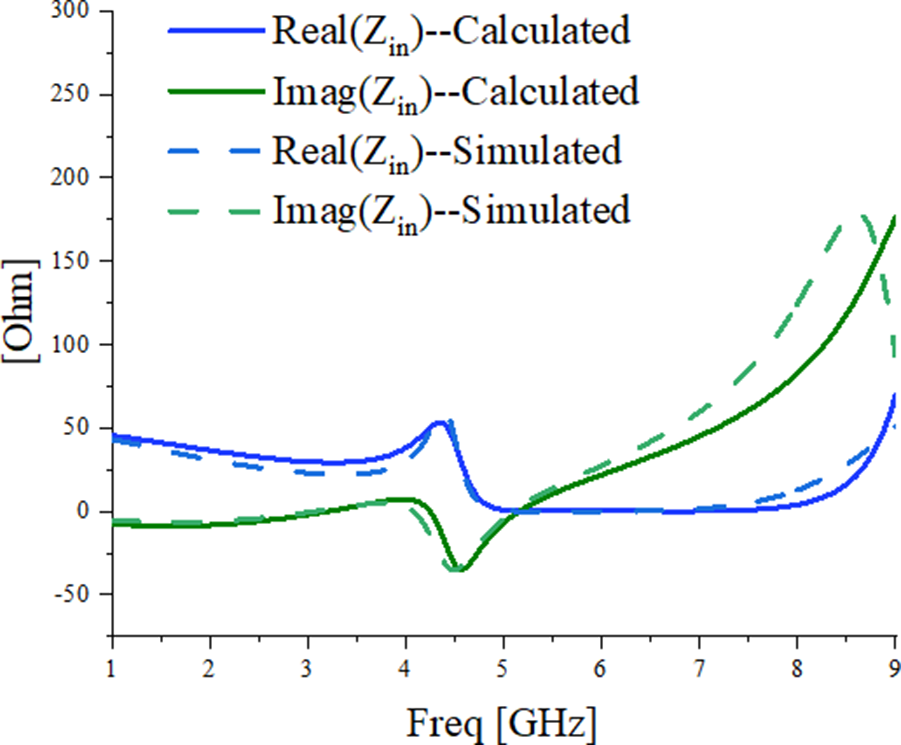
Formula (13.a) is the impedance transformation equation of SRR, in SHOMN design, and the input impedance Z inr of SRR should be within the high-efficiency region in Smith chart with the input impedance Z L of load. Formulas (13.b) and (13.c) are the even-mode and odd-mode input impedances, respectively, which is determined by the dimensional parameters of SRR. The MATLAB software is introduced to verify the correctness of the deduction above, and the calculation results of Z inr are shown in Fig. 6. In Fig. 6, the dot lines are the electromagnetism (EM) simulation results of Z inr, and it can be seen that the calculation results are very close to the simulation results; a little difference at high frequency band is caused by the introduction of two-port feedlines in EM simulation.
Calculation results and EM-simulated results of Z inr against frequency.
Note, however, that the above quantitative analysis of SRR impedance transformation characteristics has some limitations after consideration of practicality: the value of  $\sqrt {{Z_{{\textrm{0o}}}}{Z_{{\textrm{0e}}}}} $ should be controlled within the range of 20–100 ohm when c 1 = 0.2 mm (the upper limit may increase with larger c 1, but it will not exceed 120 ohm) because the microstrip lines with very wide or narrow widths will no longer follow the quasi-TEM transmission mode, and the narrower width of microstrip line, the more sensitive it is to manufacture accuracy. If the value of
 $\sqrt {{Z_{{\textrm{0o}}}}{Z_{{\textrm{0e}}}}} $ is out of range, only the theory of electromagnetic field can be used to analyze the SRR characteristics, rather than the quantitative analysis, which is required for accurate impedance matching.

High-efficiency broadband PA design
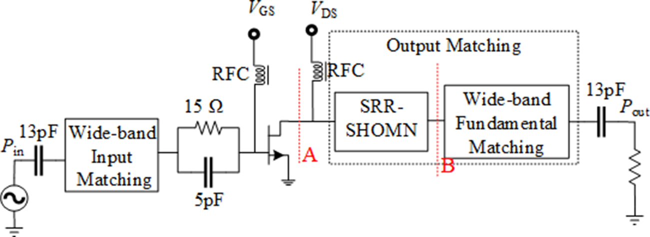
To verify the theory that SRR can act as the SHOMN of high-efficiency PA further, one PA circuit is designed with 0.762 mm Rogers 4350B substrate in this section. The transistor Wolf Speed CGH40010F with −3.0 V gate bias and 28 V drain bias is selected, and an operating frequency band of 1.2–3.0 GHz is targeted in this design. Figure 7 shows the topology of the proposed PA, and the design process is as follows.
Topology of the proposed PA.

Fundamental and harmonic components load-pull
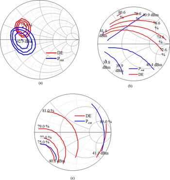
The first step to be taken is selecting the suitable output impedance region of transistor at fundamental and harmonic frequencies by using the load-pull technology repeatedly. Figure 8 presents the results of the fundamental second and third harmonic load-pull on transistor at 2.1 GHz. There is no doubt that the fundamental components have great impact on drain efficiency (DE) and output power (P out); thus, both DE and P out should be taken into consideration when selecting fundamental matching impedance. However, the second and the third harmonic components have little impact on P out, and the third components have limited impact on DE (high-efficiency region occupies the most space of chart, and the efficiency has little change with impedance), so the third components are neglected in this design.
Results of load-pull for the fundamental (a), second (b), and third harmonic (c) at 2.1 GHz.

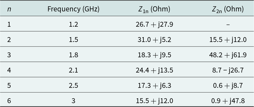
After load-pull operation, impedance is selected. There needs to be compromise between DE and P out when selecting fundamental matching impedance, and the performance compromise between two terminals of operation frequency band due to the second harmonic of low frequency coincides with high frequency. In order to ensure good performance, the load-pull technology is adopted at six fundamental frequency points in operation band; six impedances Z 1n (n = 1, 2, 3, 4, 5, and 6) are selected and are listed as in Table 1. It can be seen from Fig. 8 that the second components have little effect on P out and the high-efficiency impedances are mainly distributed in the boundary of the positive Smith chart, so the region close to the positive boundary is taken as the target of the second harmonic matching.
Impedances selected from load-pull

Drain bias circuit and SRR-SHOMN and design
The stopband of one SRR is not wide enough for such wideband harmonic matching, but it can be expanded by the 90° bias circuit.
According to the deduction in the previous section, the dimensional parameters of SRR can be determined by the formula (13) and the results of the second harmonic load-pull. Because there are five dimensional parameters in (13), five harmonic impedances at different frequencies should be chosen from the target second harmonic matching region under consideration of the introduction of bias circuit in the SRR-SHOMN design. These five impedances are chosen mutually independent, so the wideband matching can be realized by properly adjusting the frequency step between impedances. The selected five impedances Z 2n (n = 2, 3, 4, 5, and 6) are listed in Table 1, and taking them into (13), a five-element equation system can be obtained to determine the dimensional parameters of SRR-SHOMN:
 \begin{align}{Z_{2{\textrm{n}}}} & = {{{Z_{\textrm{L}}}\left( {{Z_{{\textrm{even}}}}_{{\textrm{ - 2n}}} + {Z_{{\textrm{odd}}}}_{{\textrm{ - 2n}}}} \right) + 2{Z_{{\textrm{even}}}}_{{\textrm{ - 2n}}}{Z_{{\textrm{odd}}}}_{{\textrm{ - 2n}}}} \over {2{Z_{\textrm{L}}} + {Z_{{\textrm{even}}}}_{{\textrm{ - 2n}}} + {Z_{{\textrm{odd}}}}_{{\textrm{ - 2n}}}}}{|_{{Z_{\textrm{L}}} = 50}}\nonumber \\ \qquad \qquad & \left( {n = 2,3,4,5,6} \right)\end{align}
where Z even-2n and Z odd-2n are the even-mode and odd-mode of SRR at different frequencies. Both Z even-2n and Z odd-2n have the same five independent variables Z 0e, Z 0o, θ r1, θ r2, and θ g, where θ r1, θ r2, and θ g change with frequency.
With the help of MATLAB, the final calculated parameters of SRR-SHOMN as Z e = 95 ohm, Z o = 47 ohm, Z 01 = 74 ohm, θ 1 = 3.3°, θ 2 = 14.0°, and θ g = 0.8° at 2.1 GHz corresponding to the physical dimensional parameters in Fig. 1: c = 0.8 mm, c 1 = 0.2 mm, l 1 = 0.8 mm, l 2 = 3.4 mm, and g = 0.2 mm.
Fundamental output matching network design
The dimensional parameters of SRR-SHOMN have been determined in the previous step; the impedance transformation characteristic of SRR-SHOMN is also determined, and Z 1n can be converted from plane A to plane B in Fig. 7 to simplify the design of fundamental output matching network (FOMN). Subsequently, the step impedance microstrip line structure is adopted to complete the FOMN.
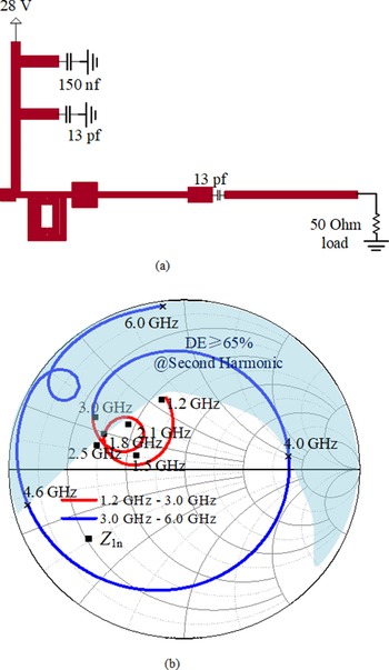
An overall output matching optimization for suitable impedance trajectories should be employed after FOMN design. Because the input impedance of SRR-SHOMN is close to the edge of the Smith chart in the second harmonic frequency range, the introduction of fundamental matching network will not significantly affect the harmonic matching. The layout of output matching network and its input impedance trajectories are presented in Fig. 9; Z 1n and the select second harmonic impedance region are also presented. It can be seen that most of the second harmonic components are well matched in the high-efficiency region, and the fundamental impedance trajectory is close to the target impedance Z 1n.
Layout of OMN (a) and input impedance trajectories (b).

Source-pull and input matching network design
Similar to FOMN structure, the input matching network is designed by the step impedance microstrip lines after six times source-pull operation to improve the performance of PA.
Implementation and measurement of PA
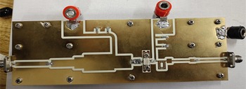
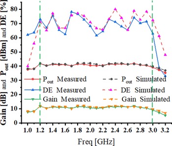
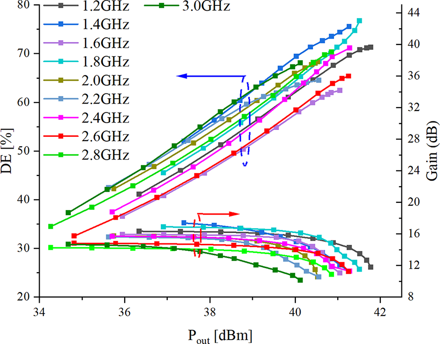
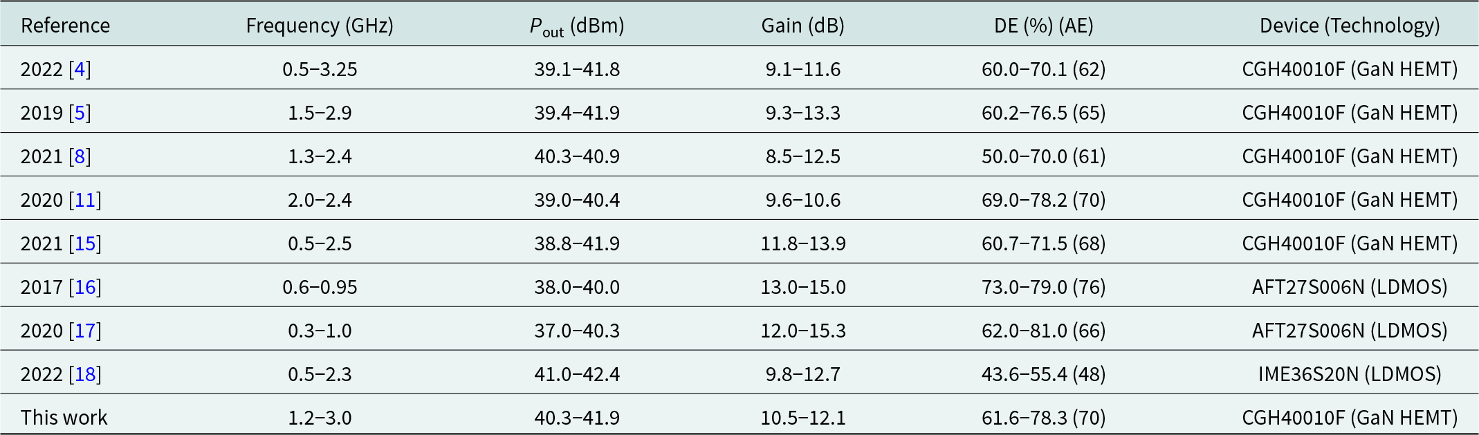
After completing the schematic design of proposed PA, the circuit is implemented and measured. The photograph of the implemented PA is shown in Fig. 10. Figure 11 depicts the results of DE, P out, and gain of PA at saturated point against frequency under one-tone signal measurement and simulation. A little discrepancy between measurement and simulation is caused by the manufacturing accuracy and antenna effect of the microstrip line. The measurement results show that the efficiency of PA is more than 61.6% in the operation frequency band (1.2–3.0 GHz), and the maximum efficiency is 78.3% at 1.8 GHz. The average output power is 41.0 dBm with average gain of 11.2 dB in the operation band. The performance at 1.5 and 2.1 GHz are relatively poor duo to the mismatch at fundamental impedance; meanwhile, the second harmonic impedance is out of the target region. Figure 12 presents the DE and gain of PA changing with output power at part of operation frequencies under measurement. Table 2 lists the performance of this work compared to the previously reported PA. It can be seen that the PA proposed in this paper achieves both the advantages of broadband and high efficiency. Although the operation bands of PAs are very wide in [Reference Latha and Rawat4], their average DE is below 62%, which is far lower than 70% of the PA in this work.
Photograph of the implemented PA.

Results of PA under one-tone signal measurement and simulation.

The DE and gain of PA changing with output power under measurement.

Comparison of this work with recently reported PAs

Conclusion
In this paper, a PA based on SRR-SHOMN is designed, and the impedance transformation of SRR is derived. Second harmonic and fundamental components are, respectively, matched by two networks, which can accurately match the impedance to the high-efficiency region in a wide frequency band. The designed PA has a broadband of 1.2–3.0 GHz, an average saturation output power of 41.0 dBm with DE of more than 61.6%. In addition, the derived impedance transformation equations of SRR make preparations for future designs with SRR technology.
Competing interests
The authors declare none.

Yu Song was born in Shandong Province, China, in 1999. He received the B.E. degree in North China University of Water Resource and Electric Power in 2021. He is pursuing the M.E. degree in the School of Electronic Information, Hangzhou Dianzi University, Hangzhou, China. His current research interests include power amplifier, microwave filter, and monolithic microwave integrated circuit.

Guohua Liu received the M.S. degree from the East China Normal University, Shanghai, China, in 2004, and the Ph.D. degree in electronic science and technology from the Hangzhou Dianzi University (HDU), Hangzhou, China, in 2020. He is currently a Professor with HDU. His research interests include microwave circuits, sensors, antennas, and wireless systems design.

Zhiqun Cheng received the B.S. and M.S. degrees from the Hefei University of Technology, Hefei, China, in 1986 and 1995, respectively, and the Ph.D. degree in microelectronics and solid state electronics from the Shanghai Institute of Metallurgy, Chinese Academy of Sciences, Shanghai, China, in 2000. From 1986 to 1997, he was a Teaching Assistant and a Lecturer with the Hefei University of Technology. He is currently a Professor with Hangzhou Dianzi University. His research interests include microwave theory and technology, MMIC, power amplifier, and RF front end.