
Introduction
Carbon nanotubes (CNTs) have attracted increasing attention as excellent reinforcements in Al matrix composites in the past two decades, due to their low density and excellent mechanical properties [Reference Tjong1, Reference Baig, Mamat and Mustapha2]. The CNT/Al composites have great potential in the lightweight structural application. However, due to the large specific surface and strong van der Waals forces, raw CNTs used for the reinforcements usually tend to be clustered in the matrix, which results in a sharp decrease of ductility. So far, to obtain CNT/Al composites with high strength, stiffness and ductility, great efforts have been made by improving the CNT dispersion, structural integrity and interfacial bonding [Reference Baig, Mamat and Mustapha2]. And a few methods, such as powder metallurgy (PM) [Reference Esawi, Morsi, Sayed, Gawad and Borah3, Reference Choi, Shin and Bae4, Reference Liu, Xu, Xiao, Xue, Wang and Ma5], severe plastic deformation (SPD) [Reference Asgharzadeh, Joo and Kim6, Reference Salimi, Izadi and Gerlich7, Reference Liu, Xiao, Wang and Ma8], semi-solid powder processing [Reference Wu and Kim9] or induction melting [Reference Mansoor and Shahid10], in situ chemical vapor deposition (CVD) [Reference He, Zhao, Shi, Liu and Li11, Reference Yang, Zou, Shi, Liu, He and Zhao12], electrochemical deposition (ED) [Reference Jiang, Li, Fan, Cao and Zhang13], and nanoscale dispersion (NSD) [Reference Kwon, Estili, Takagi, Miyazaki and Kawasaki14], have been explored to fabricate CNT/Al composites. However, dispersion by mechanical methods, such as high energy ball-milling [Reference Choi, Shin and Bae4] and SPD [Reference Salimi, Izadi and Gerlich7], would cause severe structural damage due to the strong impact force from milling balls or the shear stress during SPD, which result in the decrease of strengthening efficiency and ductility. Semi-solid powder processing [Reference Wu and Kim9] or induction melting [Reference Mansoor and Shahid10] would also cause severe damage of CNTs due to high-temperature chemical reaction between Al matrix and CNTs. As for other methods, including in situ CVD [Reference He, Zhao, Shi, Liu and Li11, Reference Yang, Zou, Shi, Liu, He and Zhao12], ED [Reference Jiang, Li, Fan, Cao and Zhang13] and NSD [Reference Kwon, Estili, Takagi, Miyazaki and Kawasaki14], although uniform dispersion of CNTs with little damage can be obtained, they are time-consuming, and are very difficult to be scaled up for industrial application. Therefore, a cost-effective method to achieve the high performance becomes necessary for the development and application of CNT/Al composites.
Among all the developed fabricating routes, PM method is preferred to prepare CNT/Al bulk composites due to its simplicity, flexibility and scalability. In general, PM process mainly has three stages comprising composite powder preparation via ball milling, densification by deformation, and subsequent annealing. And the preparation of CNT/Al composite powders is the most important, which requires the achievement of the uniform dispersion of CNT with acceptable structural integrity. In previous studies, flake PM route via slurry blending was developed by using ball-milled Al flakes to achieve the dispersion of CNTs [Reference Jiang, Li, Fan, Cao and Zhang13, Reference Jiang, Li, Fan, Cao and Zhang15], and a short-time ball milling was further employed to improve the interfacial bonding by breaking the native Al2O3 and embedding the CNTs into Al matrix [Reference Fan, Jiang, Tan, Guo, Xiong, Su, Lin, Hu, Li and Zhang16]. Very recently, Xu et al. [Reference Xu, Tan, Xiong, Fan, Guo, Zhang, Su, Li and Zhang17] proposed a flake PM route via shift-speed ball milling (SSBM), where a low-speed ball milling (LSBM) was used to flatten spherical Al powders and disperse the CNTs with low damage, and a high-speed ball milling (HSBM) was employed to improve the interface bonding under the high-energy impact of metallic balls. With uniform dispersion, high integrity of CNTs and good interface bonding, SSBM provided an effective way to produce CNT/Al composite powders used as starting materials in PM process. After the successful achievement of composite powders, densification via deformation and subsequent annealing were further employed to produce the final CNT/Al products.
So far, extrusion deformation is the most preferred route to fabricate CNT/Al bulk materials via PM process. Although CNT/Al flat products of lightweight structural materials are needed in some application, only a few studies [Reference Guo, Ni, Yi, Shen, Tang, Du and Song18, Reference Choi, Shin and Bae19, Reference Liu, Xiao, Wang and Ma20] reported the fabrication of flat product by rolling process, and the balance between strength and ductility still remains as a challenge in CNT/Al flat products. For example, Guo et al. [Reference Guo, Ni, Yi, Shen, Tang, Du and Song18] achieved a high ductility higher than 15% in CNT/Al flat product by spark plasma sintering (SPS) plus conventional hot rolling, but the tensile strength was lower than 250 MPa. On the contrary, Choi et al. [Reference Choi, Shin and Bae4] achieved a high tensile strength above 500 MPa by hot-rolling of ball-milled CNT/Al composite powders, but the ductility was lower than 5%. Compared with extrusion, rolling process will produce different microstructural evolution due to the multi-step rolling reduction and only two directions of deformation restriction along the rolling and normal direction (RD and ND). In addition to CNTs, the texture of flat products may also play an important role in determining the mechanical properties of rolled composites [Reference Zhang, Wang, Yang, Li, Ni, Du and Song21]. Therefore, to develop a cost-effective route to prepare rolled composites and adjust the mechanical properties will be necessary for the development and application of CNT/Al flat product with high strength and ductility.
In this work, flake PM via SSBM and hot-rolling was used to fabricate rolled CNT/Al composites. The CNT/Al composite powders were prepared by SSBM, followed by compressing, sintering, and hot-rolling and subsequent annealing. Finally, CNT/Al flat products were successfully fabricated by flake PM via SSBM and conventional rolling. The balance between high strength and ductility was achieved in the composites with 1.5 wt% CNTs addition. The evolution of CNTs and effect of CNT content on the mechanical properties were also discussed.
Results
Morphology of SSBM CNT/Al powders
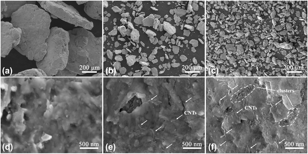
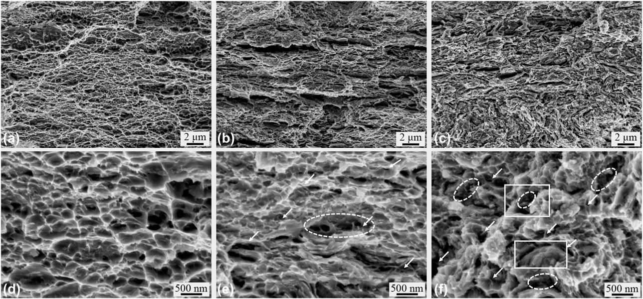
As reported in previous work [Reference Xu, Tan, Xiong, Fan, Guo, Zhang, Su, Li and Zhang17], there were two stages of ball milling processes. For the first stage of LSBM at 135 rpm, spherical Al powders were gradually ball-milled into nano-flake powders accompanied by gradual dispersion of CNTs on the surface of Al flakes. SEM images of CNT/Al flake after LSBM can be found in Fig. S1. When the content of CNTs was 1.5 wt%, CNTs uniformly dispersed on the surface of Al flakes. However, when it was up to 3 wt%, some clusters of CNTs remained on the surface. Then, during the HSBM at 270 rpm, CNT/Al composite powders were further ball-milled into flat cold-welded particles, and strong inter-flake bonding was obtained due to high-speed impact from the milling balls. Morphology of pure Al and CNT/Al composite powders after SSBM are shown in Fig. 1. All the flake powders were cold-welded into flat particles, and the size of particles decreased from several hundred microns for pure Al powders to less than 100 μm for 3 wt% CNTs added powders. The enlarged surface images of particles were presented in Figs. 1(d) and 1(e). As shown in Figs. 1(e) and 1(f), dispersed individual CNTs were clearly observed, and the length of most CNTs ranged between 200 and 400 nm. For the 1.5 wt% CNTs added samples, CNTs uniformly dispersed on the surface with few clusters. However, much higher density of CNTs can be observed on the surface of composites with 3 wt% CNTs. Meanwhile, because there is no enough space to disperse 3 wt% CNTs, and some slight clusters were still found in the inter-flake district surrounded by the white dot-lines in Fig. 1(f).
SEM images of cold-welded particles (a–c) and their enlarged surfaces (d–f): Pure Al (a, d); CNT/Al composite particles with (b, e) 1.5 wt% CNTs, and (c, f) 3 wt% CNTs.

Evolution and distribution of CNTs
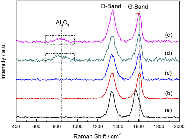
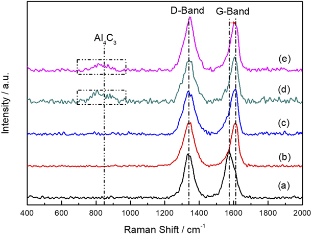
To investigate the evolution of CNTs during flake PM process, Raman analysis was performed on the samples with 1.5 wt% CNTs. Raman spectrums in Fig. 2 shows the evolution of CNTs during the whole flake PM process. Two main peaks located at ∼1580 cm−1 (G-band) and ∼1350 cm−1 (D-band) are often used to characterize the structure of CNTs, which reveal the crystalline structure and presence of defects in graphite layers, respectively. Therefore, the change of intensity ratio of D- and G-bands (I D/I G) represents the structural evolution of CNTs. Compared with the raw CNTs, no obvious change of I D/I G was found in the Figs. 2(b)–2(d), and a slighter higher I D/I G were found in Fig. 2(e). The little change of I D/I G indicates the structure of CNTs was well preserved during the whole fabricating process of CNT/Al composites. However, we can find a red-shift of G-band, which was possibly related to the residual strain [Reference Chen, Li, Imai, Lei, Umeda, Takahashi and Kondoh22], bonding condition and even the infiltration of Al atoms in CNTs [Reference Choi, Shin, Min, Park and Bae23]. In addition, compared with Figs. 2(a)–2(c), sluggish hump around characteristic peak of Al4C3 (∼860 cm−1 [Reference Chen, Jia, Li, Imai, Takahashi and Kondoh24]) appeared in Figs. 2(d) and 2(e), indicating a little interfacial reaction in the as-rolled and annealed rolled composite.
Raman spectrums of (a) raw CNTs, and composite with 1.5. wt% at different stages: (b) cold-welded particles, (c) as-sintered cold-compacted ingot, (d) as-rolled and (e) annealed rolled composite.
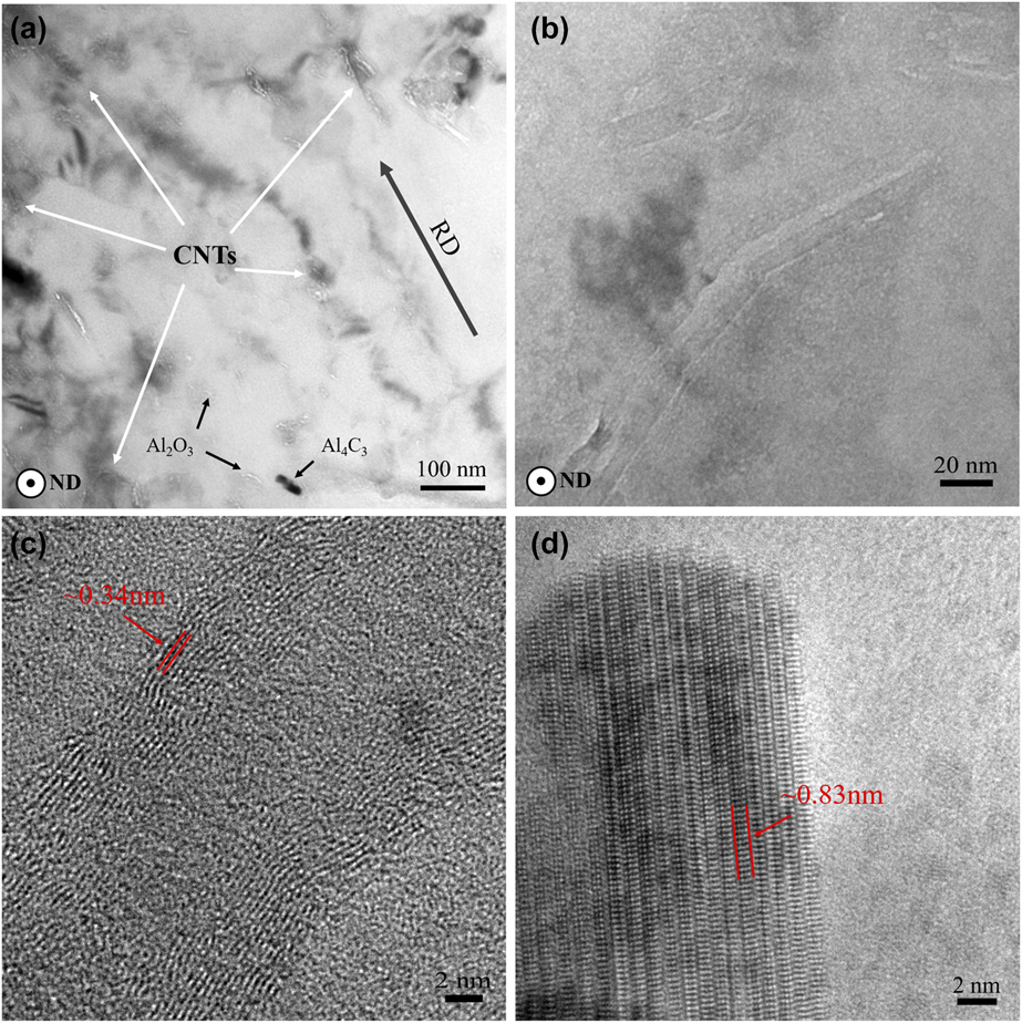
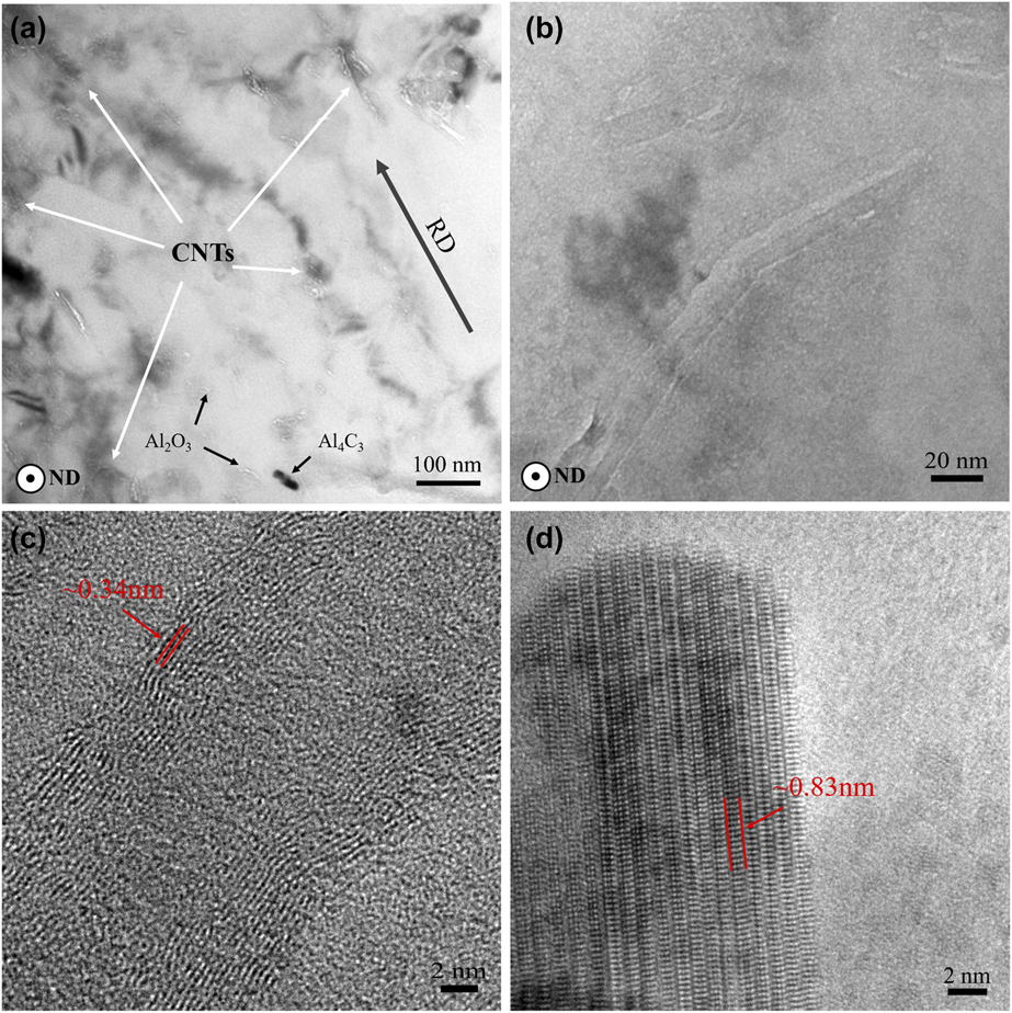
TEM was further used to characterize the distribution and structural evolution of CNTs in CNT/Al composite. TEM images in Fig. 3 were obtained on the normal direction of CNT/Al rolled composite with 1.5 wt% CNTs. Most of CNTs are uniformly dispersed in the Al matrix as shown in Fig. 3(a), and there were no obvious clusters of CNTs. Besides, as shown in Fig. 3(a), CNTs were found to be aligned unidirectionally to some extent, which should be the rolling direction (RD) due to the shear stress during rolling process [Reference Liu, Xiao, Wang and Ma20]. In addition to CNTs, a few reaction products of Al4C3 and fragmented Al2O3 nanoparticles were also found in the Al matrix. A clear image of individual CNT is presented in Fig. 3(b). As shown in Fig. 3(b), after all the preparing process, the CNTs in Al matrix still remained highly intact with little defect. The CNTs and Al4C3 were further confirmed by the high-resolution transmission electron microscopy (HR-TEM) images in Figs. 3(c) and 3(d) with the interplanar spacing value of ∼0.34 and ∼0.83 nm in the lattice fringes, which correspond to the interplanar spacing of (0002) of graphite and (0003) of Al4C3, respectively. Meanwhile, well bonded interface of Al/CNT can also be observed in Fig. 3(c).
TEM images of CNT/Al composite with 1.5 wt% CNTs: (a) TEM microstructure, (b) an individual CNT in Al matrix, and HR-TEM images of (c) CNT and (d) Al4C3.
XRD and macro-texture of rolled CNT/Al composites
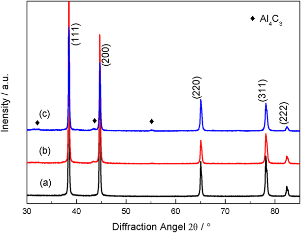
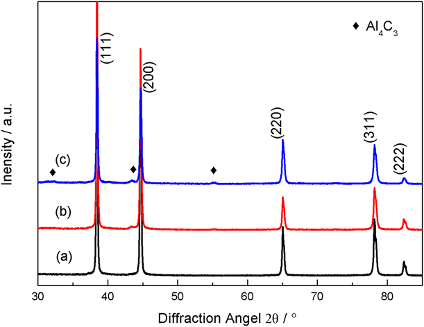
X-ray diffraction (XRD) were used to analyze the structural evolution of matrix, and XRD patterns on the TD-RD plane of annealed samples are presented in Fig. 4. Diffraction peaks of Al matrix were the main diffraction peaks of samples. In addition to the Al peaks, weak peak of reaction product Al4C3 can be also be observed, which is consistent with the observation in Figs. 2 and 3. The equivalent average grain size of Al matrix can be calculated by the Williamson–Hall equation [Reference Williamson and Hall25]
 $${\beta _{\rm{s}}} \cdot \cos \;\theta = {{K\lambda } \over d} + 2\varepsilon \cdot \sin \;\theta \quad ,$$
where βs is the peak broadening, θ is the Bragg angle, K is ∼0.9, λ is the wavelength of Cu Kα (0.154 nm), d is the grain size, and ε is the microstrain, respectively. The true peak broadening can be corrected by standard samples according to Gaussian–Gaussian relationship:  ${\beta _{\rm{s}}} = \sqrt {\beta _{\rm{e}}^2 - \beta _{\rm{i}}^2}$, where βe and βi is the measured full-width at half-maximum (FWHM) of XRD peaks and instrumental broadening, respectively. Based on the XRD results in Fig. 4, the obtained average grain size is 1031 nm, 539 nm and 335 nm for pure Al and composites with 1.5 and 3 wt% CNTs, respectively.
XRD patterns of annealed samples: (a) Pure Al, and composites with (b) 1.5 wt% CNTs and (c) 3 wt% CNTs.
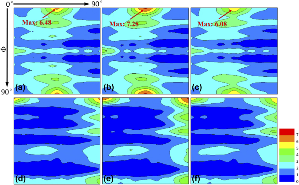
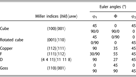
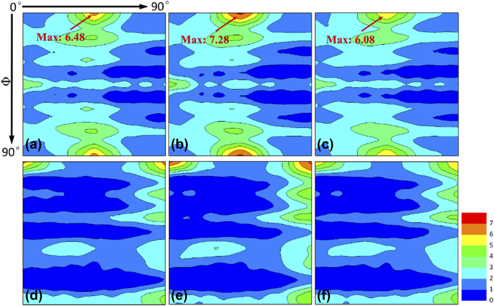
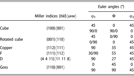
XRD pole figures were performed on the rolling direction-transverse direction (RD-TD) plane, and orientation distribution function (ODF) plots were obtained to analyze the crystallographic texture of CNT/Al rolled composites. The ODF plots at the φ2 = 0° and φ2 = 45° section are shown in Fig. 5, and the corresponding Euler angle of main texture components on the ODF plots are shown in Table I. Generally, there was little difference in the main texture components for all the three samples. And the dominant component was the shear texture of rotated cube texture {001}〈110〉. Compared with the other two samples, a slightly higher intensity of {001}〈110〉 can be found for the composite with 1.5 wt% CNTs. In addition to the rotated cube texture, other weaker texture components also remained in the annealed sheets, including Goss {110}〈001〉, Copper {112}〈111〉, D {4 4 11}〈11 11 8〉 and F {111}〈112〉.
ODF plots at (a–c) φ2 = 0° and (d–f) φ2 = 45° sections of annealed rolled composites on the RD-TD planes: (a, d) Pure Al, and composites with (b, e) 1.5 wt% CNTs and (c, f) 3 wt% CNTs.
Miller indices and Euler angles of texture components.
Mechanical properties and fracture morphology
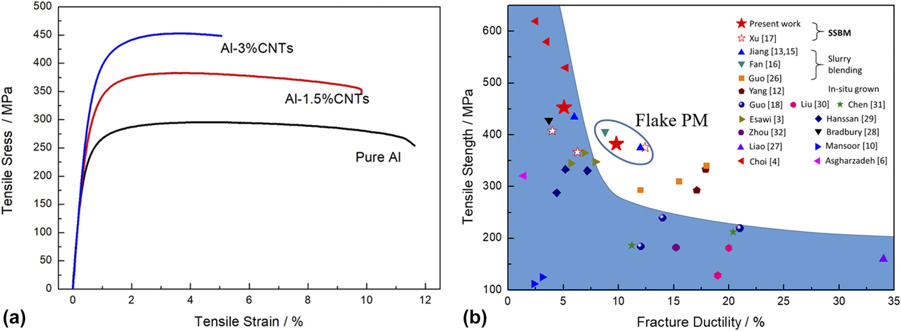
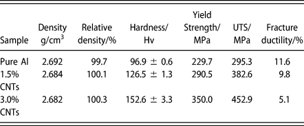
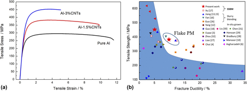
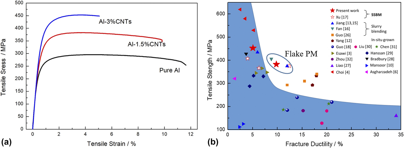
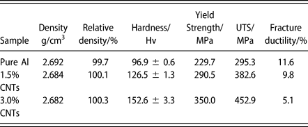
Tensile stress–strain curves of annealed Al and CNT/Al composites are shown in Fig. 6(a), and values of tensile testing results are furnished in Table II. In addition, values of density and hardness are also presented in Table II. Almost full density with little porosity was obtained in the final product. May attributed to the oxidation of Al powders during PM processing, relative density above 100% was obtained in the CNT/Al composites. In general, the addition of CNTs greatly increased the hardness and tensile strength. In the pure Al matrix, the hardness and yield strength were 96.9 ± 0.6 Hv and 229.7 MPa, respectively. The addition of 1.5 and 3.0 wt% CNTs increased the hardness by 29.6 and 55.7 Hv, respectively. And the increase of yield strength was up to 60.8 MPa and 120.3 MPa for the 1.5 and 3.0 wt% CNTs, respectively. However, the ductility decreased with increasing CNTs, and it was only 5.1% in the sample with 3 wt% CNTs, which was much lower than 11.6% in pure Al matrix. Interestingly, with 1.5 wt% CNTs addition, the UTS (Ultimate tensile strength) increased to 382.6 MPa, meanwhile, the fracture ductility still remained up to 9.8%. Comparison of strength and ductility of CNT/Al composites in this work and other studies [Reference Esawi, Morsi, Sayed, Gawad and Borah3, Reference Choi, Shin and Bae4, Reference Asgharzadeh, Joo and Kim6, Reference Mansoor and Shahid10, Reference Yang, Zou, Shi, Liu, He and Zhao12, Reference Jiang, Li, Fan, Cao and Zhang13, Reference Jiang, Li, Fan, Cao and Zhang15, Reference Fan, Jiang, Tan, Guo, Xiong, Su, Lin, Hu, Li and Zhang16, Reference Xu, Tan, Xiong, Fan, Guo, Zhang, Su, Li and Zhang17, Reference Guo, Ni, Yi, Shen, Tang, Du and Song18, Reference Guo, Zhang, Cen, Chen, Wang, Song, Ni, Yi, Shen and Du26, Reference Liao, Tan and Sridhar27, Reference Bradbury, Gomon, Kollo, Kwon and Leparoux28, Reference Hassan, Esawi and Metwalli29, Reference Liu, Xiao, Wang and Ma30, Reference Chen, Kondoh, Imai, Umeda and Takahashi31, Reference Zhou, Yamaguchi, Kikuchi, Nomura and Kawasaki32] are shown in Fig. 6(b). Obviously, most of CNT/Al composites exhibited a trade-off dilemma in strength and ductility, which located under the typical “banana curve”. The sample with 1.5 wt% CNTs located above “banana curve” in the present work, which indicates the balance between high strength and ductility was successfully achieved.
(a) Tensile stress–strain curves of annealed samples, (b) Comparison of tensile property of CNT/Al composites [Reference Esawi, Morsi, Sayed, Gawad and Borah3, Reference Choi, Shin and Bae4, Reference Asgharzadeh, Joo and Kim6, Reference Mansoor and Shahid10, Reference Yang, Zou, Shi, Liu, He and Zhao12, Reference Jiang, Li, Fan, Cao and Zhang13, Reference Jiang, Li, Fan, Cao and Zhang15, Reference Fan, Jiang, Tan, Guo, Xiong, Su, Lin, Hu, Li and Zhang16, Reference Xu, Tan, Xiong, Fan, Guo, Zhang, Su, Li and Zhang17, Reference Guo, Ni, Yi, Shen, Tang, Du and Song18, Reference Guo, Zhang, Cen, Chen, Wang, Song, Ni, Yi, Shen and Du26, Reference Liao, Tan and Sridhar27, Reference Bradbury, Gomon, Kollo, Kwon and Leparoux28, Reference Hassan, Esawi and Metwalli29, Reference Liu, Xiao, Wang and Ma30, Reference Chen, Kondoh, Imai, Umeda and Takahashi31, Reference Zhou, Yamaguchi, Kikuchi, Nomura and Kawasaki32].
Mechanical properties of final annealed samples.
The ductility of composites is determined by the fracture behavior. Fracture morphology after the tensile test is presented in Fig. 7. Obvious ductile fracture feature with many dimples was observed in pure Al sheets. With the addition of CNTs, the fractography image gradually changed from ductile to brittle feature, and brittle fractography was found in Fig. 7(c) with 3 wt% CNTs addition. Enlarged images of fractography were presented in Figs. 7(d)–7(f). Compared with pure Al, dimples in 1.5 wt% CNTs added samples became shallower in Fig. 7(e), indicating a slightly lower ductility. Meanwhile, we can find some individual CNTs pulled out or bridged on the fractography images, as shown in the while dot-line circle. When the addition of CNTs was up to 3 wt%, much fewer dimples were found, and partial brittle fracture feature emerged in Fig. 7(f). In addition to individual CNTs, we can also find some hollows with CNT clusters, as shown in the white circles. Meanwhile, as shown in the white rectangles in Fig. 7(f), partial district exhibited the brittle fractography feature with smooth surface, deep hollows and CNTs clusters.
Fractography images of samples: (a, d) Pure Al, and composites with (b, e) 1.5 wt% CNTs and (c, f) 3 wt% CNTs. The white arrows in (e and f) point the CNTs.

Discussion
Microstructural evolution of CNT/Al composites via SSBM and hot-rolling
Reinforcements of CNTs is the most important factor in determining the mechanical properties of CNT/Al composites. The dispersion mechanism of CNTs during SSBM has been discussed in previous work [Reference Xu, Tan, Xiong, Fan, Guo, Zhang, Su, Li and Zhang17]. In general, for the conventional PM processes, the original spherical Al powders will experience three stages: flattened from spherical powders, cold welded into lamellar-structure particles, and fragmented into smaller particles [Reference Esawi and Morsi33]. During the co-milling with Al powders in the BM processes, raw CNTs with clusters get dispersed under the shear stress from the milling balls. In the first stage of LSBM process, there is enough time to break up the CNTs clusters before flattened powders get cold-welded. Meanwhile, with the thickness decrease of flattened Al powders, the surface of flake powders greatly increases, which provides enough space to place the dispersed CNTs. Then, during the second stage of HSBM, the flake CNT/Al composite powders get cold-welded, and the dispersion of embedded CNTs will keep uniform till to the final flat product. However, there is a thickness limitation (∼200 nm [Reference Xu, Tan, Xiong, Fan, Guo, Zhang, Su, Li and Zhang17]) during the flattening of spherical Al powders in the present work, resulting in a space limitation for the dispersion of CNTs. As shown in Fig. 1, in the present SSBM parameters, though uniform dispersion of 1.5 wt% CNTs was achieved, some slight CNT clusters still remained when the CNTs was up to 3 wt%, and weaker infer-flake bonding was expected due to the high density of CNTs on the flake surface.
In addition to the dispersion, the structural integrity of CNTs and interfacial bonding also act as an important role in determining the mechanical properties. During the HSBM, under the strong impact effect from milling balls, CNTs were embedded into the cold-weld particles, but very limited damage can be imposed on the CNTs due to the very limited high-speed milling time and the buffer layer of Al matrix. As shown in the Raman spectrum in Fig. 2, only a slight change of I D/I G after HSBM was observed compared with the raw CNTs. However, due to the impact of milling balls, little structural damage of partial CNTs was still unavoidable, and those damaged CNTs tended to react with Al matrix under the influence of rolling and heating, causing the sluggish hump around Al4C3 peak in the as-rolled and annealed samples. Besides, it was reported that, the HSBM can also break the native Al2O3 surface nanolayer on the Al flake powders, resulting in an improvement of CNT-Al interface bonding during the following deformation and annealing processes [Reference Fan, Jiang, Tan, Guo, Xiong, Su, Lin, Hu, Li and Zhang16].
Macro-deformation, including extrusion and rolling, is another factor influencing the mechanical properties of CNT/Al composites. On the one hand, due to the shear stress, rolling process will further improve the distribution of CNTs in the Al matrix. In fact, a few early studies also used the conventional rolling equipment to disperse CNTs, such as high-ratio differential speed rolling (HRDSR) [Reference Yoo, Han and Kim34] and accumulative rolling bonding (ARB [Reference Salimi, Izadi and Gerlich7]), however, CNTs were seriously damaged due to the large shear strain. After ball-milling dispersion of CNT/Al composite powders, the dispersion will be further improved by using multi-steps rolling with proper reduction, and limited structural damage was caused in the present study. Meanwhile, similar with extrusion process, due to the unidirectional rolling shear stress, CNTs will be directional aligned along the RD, as reported in previous work by Liu [Reference Liu, Xiao, Wang and Ma20]. As shown in Fig. 3(a), CNTs in the Al matrix were aligned unidirectional in the present work, which is helpful for the load-transfer mechanism [Reference Ryu, Cha and Hong35].
On the other hand, macro-rolling deformation will also produce rolling texture. In the present study, rotated cube {001}〈110〉 dominate the texture components in the annealed CNT/Al composites via SSBM and hot-rolling. Usually, {001}〈110〉 texture forms as the shear texture in the Al flat product, which has resulted from the large shear stain [Reference Zhang, Wang, Yang, Li, Ni, Du and Song21, Reference Jamaati, Toroghinejad, Hoseini and Szpunar36]. The remaining component of the shear texture instead of the recrystallization texture, such as {100}〈001〉, was also observed in a previous work about annealed PM Al-alloy flat product [Reference Eddahbi, Carsı and Ruano37]. Besides, other rolling textures, such as {112}〈111〉 and {4 4 11}〈11 11 8〉, also remained in the annealed sheets. One probable reason is that the large amount of CNTs combined with fragmented nano-Al2O3, imposed a strong pinning effect which retarded the recrystallization texture in the rolled composites [Reference Jamaati, Toroghinejad, Hoseini and Szpunar36].
Strengthening mechanism of the CNT/Al rolled composites with various CNTs
The tensile strength of CNTs/Al composites is determined by the combined effect of matrix and reinforcement, mainly including the grain boundary strengthening, load transfer from matrix to CNTs, and Orowan looping [Reference Baig, Mamat and Mustapha2]. The Orowan strengthening of CNTs is considerable only when matrix grains are much larger than reinforcements, and CNTs are usually found on the grain boundaries. Therefore, Orowan mechanism of CNTs is little in the ultra-fined grain CNT/Al composites [Reference Choi, Shin and Bae19, Reference Choi, Kwon, Lee and Bae38]. The addition of CNTs would greatly refine the matrix grain size due to the pinning effect, resulting in an increase of grain boundaries strengthening. Without considering of nanoparticles, such as the interfacial product of Al4C3 and fragmented native Al2O3, and supposing the Al matrix is homogenous, then the increased strength ΔσH due to the refined matrix grains can be calculated as
 $$\Delta {\sigma _{\rm{H}}} = k\left( {d_1^{ - {1 \over 2}} - d_0^{ - {1 \over 2}}} \right)\quad ,$$
where k is the Hall–Petch constant of Al (0.04 MPa/m1/2 [Reference Hansen39]), and d 1 and d 0 are the grain size of specimen and reference, respectively. Using the average grain size based on XRD results (namely, 1031 nm, 539 nm and 335 nm for pure Al, and composites with 1.5 and 3 wt% CNTs, respectively), then the increased yield strength for composites with 1.5 and 3 wt% CNTs are 15.1 MPa and 29.2 MPa, respectively.
The load transfer is strongly related to the aspect ratio, structural integrity of CNTs and interfacial bonding of CNT-Al. Considering the load transfer and the alignment of CNT along the RD, the increased strength ΔσY using the shear lag model [Reference Ryu, Cha and Hong35] can be expressed as follows
 $$\Delta {\sigma _{\rm{L}}} = 0.5{\sigma _{\rm{M}}}{V_{{\rm{CNTs}}}}S\quad ,$$
where σM is the strength of Al matrix, and V CNTs is the volume fractions of CNTs (1 wt% CNTs equals ∼1.5 vol% CNTs). And S is the aspect ratio of CNTs, which is about 15 using the average value of 20 nm for the diameter and middle value of 300 nm for the length of CNTs in composites. Supposing the matrix of composites are homogenous, and σM increases with the decrease of grain size, then the increased strength of composites due to the load transfer are 41.3 and 87.4 MPa for the composites with 1.5 and 3 wt% CNTs.
By summing the contribution of load transfer and grain boundary strengthening, the calculated values of increased yield strength are 56.4 MPa and 116.6 MPa for the 1.5 and 3.0 wt% CNTs addition, respectively. Those two values well matched with the measured ones in Fig. 6(a) and Table II, with only a slight decrease. The decreased values may result from the limited influence of thermal mismatch and Orowan strengthening from nano-dispersoids, such as the interfacial product of Al4C3 and fragmented native Al2O3 [Reference Baig, Mamat and Mustapha2]. In addition, it was reported that the texture effect would also affect the tensile property in other studies about Al and Al/CNT composites [Reference Lee, Chen, Kao, Chang, Tseng and Su40, Reference Wei, Li, Xiong, Tan, Fan, Qin and Zhang41]. However, no obvious relationship between texture and strength was observed in present study due to the little difference of main texture components in Fig. 5.
Balanced strength and ductility of the CNT/Al composites via SSBM and hot-rolling
As shown in Fig. 6(b), both CNT/Al rolled and extruded composites 1.5 wt% CNTs via SSBM achieved the balance between high strength and ductility. Compared with the ductility (∼12.4%) of extruded CNT/Al composites [Reference Xu, Tan, Xiong, Fan, Guo, Zhang, Su, Li and Zhang17], a slighter lower ductility was obtained in the rolled composites, which may be attributed to lower equivalent strain during macro-deformation with restriction along only two directions of RD and ND. As mentioned above and discussed in previous work [Reference Xu, Tan, Xiong, Fan, Guo, Zhang, Su, Li and Zhang17], the advantage of SSBM is the uniform dispersion with good structural integrity and interfacial bonding. Local stress concentration and early failure due to the CNTs clusters and brittle phases such as Al4C3 and native Al2O3 were sharply reduced. Meanwhile, as shown in the white circle in Fig. 7(e), some individual CNTs pulled-out or bridged were found on the fractography surface, which restricted the crack propagation and further improved the ductility. Finally, remarkable increase of increase with little decrease of ductility was obtained in the composites with 1.5 wt% CNTs.
However, as discussed above, due to the limited surface of Al flakes, there is a limitation for the dispersed CNTs. When the CNTs contents were increased up to 3 wt%, the density of CNTs on the ball-milled Al flakes after LSBM was so high that the strong inter-flake bonding during HSBM and densification became difficult. As shown in Figs. 1(f) and 7(f), a few little CNT clusters residue were found in the inter-flake space in the cold-welded particles, and were left in the final CNT/Al flat product, resulting in the crack nucleation and propagation along the original interface of original Al flakes. Therefore, it was thought that the 3 wt% content of CNTs was so high that resulted in the poor interface bonding between Al nano-flakes. And those district with poor interfacial bonding and CNTs clusters would act as crack nucleation under the tensile loading, resulting in the decrease of ductility. Therefore, optimization of preparing parameters is further needed to improve the ductility of composites with high CNTs content. For example, to increase the content of uniform dispersed CNTs, it is available to increase the surface area of Al flakes by optimizing the LSBM parameters. Besides, it is also available to break up the clusters in the final flat product by optimizing the macro-rolling parameters.
In conclusion, CNT/Al rolled composites with balanced strength and ductility were successfully achieved flake PM via SSBM and conventional hot-rolling. It should be noted that the mechanical performance of CNT/Al flat product in this work can be easily further tailored by adjusting the SSBM and final hot-rolling parameters. Although previous work [Reference Yang, Zou, Shi, Liu, He and Zhao12, Reference Jiang, Li, Fan, Cao and Zhang15, Reference Fan, Jiang, Tan, Guo, Xiong, Su, Lin, Hu, Li and Zhang16, Reference Guo, Zhang, Cen, Chen, Wang, Song, Ni, Yi, Shen and Du26] also achieved the balance between high strength and ductility in the CNT/Al composites, most of them are extruded products via in situ route or slurry blending, which is difficult for extensive industrial application. The successful achievement of CNT/Al rolled composites in this work provides a smarter and more cost-effective route for the potential industrial application of CNT/Al flat product.
Conclusions
In this work, flake PM via SSBM and hot-rolling was demonstrated to be an effective route to fabricate the CNT/Al rolled composites. The evolution of CNTs and Al matrix was investigated, and mechanical performance of composites with various CNTs were discussed. Following conclusions can be drawn:
(1) Flake PM via SSBM and hot-rolling is an effective and smart route to prepare CNT/Al flat products. Mechanical properties can be tailored by adjusting the CNTs contents, meanwhile, there is a great potential of further performance improvement via the fabrication optimization of conventional ball-milling system and rolling equipment.
(2) Due to the combined effect of SSBM and rolling, CNTs uniformly dispersed in the Al matrix with little damage and directional alignment. With proper CNTs content, the balance between high strength and ductility can be achieved in the CNT/Al flat product, and 382.6 MPa in tensile strength and 9.8% in fracture ductility were obtained in the rolled composites with 1.5 wt% CNTs in the present work.
(3) Load transfer was the main mechanism of the increased yield strength with CNTs addition. Meanwhile, CNTs resulted in the decrease of matrix grain size, which also contributed to the strength enhancement. In addition, strong shear texture of rotated cube {001}〈110〉 was found in the final annealed rolled composites.
Experimental
Raw material and composite preparation
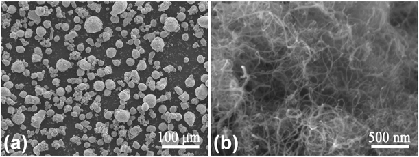
Atomized spherical Al powders (average diameter of ∼30 μm and 99.8% in purity, provided by Bai Nian Yin Industry & Trade Co., Ltd., in Zhejiang, China) and multi-walled CNTs (∼20 nm in diameter and 1–5 μm in length, provided by Cnano Technology Ltd., in Jiangsu, China) were chosen to fabricate the CNT/Al rolled composites. SEM images of raw materials of Al powders and CNTs are shown in Fig. 8. Pure Al powders, and Al powders with 1.5 and 3.0 wt% CNTs of total weight of Al powders were firstly mechanical mixed in a 3D mixer for 4 h, followed by planetary ball milling under the protection of Ar. The revolution radius and rotation radius of the planetary ball milling system were 300 mm and 90 mm, respectively. Milling balls of GCr15 stainless steel with diameter of 8 mm were used during milling process. The ball-to-powder ratio was 20:1, and 1 wt% stearic acid was added as the process control agent (PCA). Similar with previous study [Reference Xu, Tan, Xiong, Fan, Guo, Zhang, Su, Li and Zhang17], a SSBM process at 135 rpm for 8 h plus 270 rpm for 0.5 h was used to produce composite particles, and vacuum annealing at 375 °C for 3 h was used to eliminate the PCA after the LSBM at 135 rpm. Those ball-milled particles were then cold pressed into φ40 mm ingots at 500 MPa, followed by vacuum sintering at 540 °C for 2 h, and hot-forged at 450 °C with a ∼30% reduction along the cold-pressed direction. The forged ingots were then hot-rolled at 480 °C to 1.5 mm with a total ∼85% rolling thickness reduction. The as-rolled sheets were further annealed at 500 °C for 2 h to obtain the final flat product.
SEM images of raw material: (a) Al powders and (b) CNTs.

Structural characterization and mechanical property testing
Microstructures of CNT/Al powders and flat composites were characterized using field emission scanning electron microscopy (FE-SEM; Tescan Mira 3, Tescan, Czech Republic) and high-resolution transmission electron microscopy (HR-TEM; JEOL JEM-2010). Raman spectroscopy analysis of CNTs structure in the composite were performed 532 nm Ar+ laser in Senterra R200-L, Bruker Optics, Germany. The analysis of phase and texture were performed on the RD-TD plane of 1/5 thickness under the surface using XRD equipment of D8 Advance Da Vinci, Bruker, Germany, and ODF figures were obtained to analyze the information of macro-texture. The density of annealed samples was measured by Archimedes’ method. Vicker hardness was measured with load of 294.2 N and 15 s dwell time using Brinell Rockwell & Vickers Optical Hardness Tester of HBRVU-187.5, Shanghai Lianer Testing Equipment Co., Ltd., China, and at least eight positions were measured to obtain an average value. Tensile specimens were machined along the RD with a gauge length of 10 mm, and tested at a constant strain rate of 5 × 10⁻⁴/s at room temperature using uniaxial tension testing machine of Model 3344, Instron, Massachusetts.
Supplementary material
To view supplementary material for this article, please visit https://doi.org/10.1557/jmr.2019.219.
Acknowledgments
The authors would like to acknowledge the financial support from the National Key Research and Development Program of China (Nos. 2017YFB1201105 and 2016YFB1200506), the Natural Science Foundation of China (Nos. 51671130 and 51871149), National Postdoctoral Program for Innovative Talents (BX201700148), and Shanghai Science & Technology Committee Nos. 17ZR1441500 and 19ZR1474900.