I. INTRODUCTION
Volumetric metamaterials (MTMs) consist of a host medium in which proper insertions are located. Either a single specifically shaped element, also known as a particle, or a suitably spatially arranged set of particles forms the unit cell of the MTMs. The particles are anisotropic. Consequently, the medium composed of particles generally also has an anisotropic response to an irradiating wave. Planar resonant particles are most suitable for these purposes due to their simple fabrication. These particles can show negative permittivity, permeability, or both these parameters can be negative. Probably the most important publication in MTMs is [Reference Pendry, Holden, Robbins and Srewart1] as it has proposed a small resonant particle, a split ring resonator (SRR), the basic constituent of artificial negative permeability media – mu-negative (MNG) MTM. The broadside-coupled (BC) SRR was designed in [Reference Marqués, Mesa, Martel and Medina2] as the particle not showing bianisotropic behavior. BC-SRR uses both substrate sides and its capacitance can be designed with a very high value resulting in a low resonant frequency. When irradiated by an electromagnetic wave, S-shaped SRRs produce negative permeability [Reference Chen3]. A number of planar resonant particles showing negative permittivity – epsilon-negative (ENG) particles – have been presented in the literature, e.g., in [Reference Schuring, Mock and Smith4]. A particle consisting of an electric dipole terminated by an inductor was reported in [Reference Machac, Protiva and Zehentner5]. A left-handed MTM can be obtained by combining the particles in a proper way, as has been done in [Reference Chen6, Reference Chen7] using S-shaped SRRs.
There are two ways that lead to isotropy of an MTM composed of planar resonant particles. The first way utilizes a specific form of the unit cell satisfying symmetry of the selected crystallographic group and its periodical arrangement in space [Reference Machac, Protiva and Zehentner5, Reference Baena, Jelinek, Marques and Zehentner8]. The second way is based on randomly located unit cells in the volume of the host [Reference Jelinek, Machac and Zehentner9].
This paper is an extension of [Reference Machac, Rytir, Protiva and Zehentner10] and its objective is to report the design and fabrication of a volumetric isotropic ENG MTM applying a new kind of planar particle denoted as a double H-shaped resonator (DHR). This particle is of a resonant nature, and consequently its operation is frequency selective. The interaction of the exciting field with the particle results in negative effective permittivity in a narrow frequency band above its resonant frequency. The layout of this particle is shown in Fig. 1(a). The particle was designed and fabricated, and its response to an exciting electromagnetic wave is analyzed together with the influence of the second coupled DHR resonator located in its proximity. The six DHR particles are assembled to form a cube, as described in [Reference Baena, Jelinek, Marques and Zehentner8], to obtain an ENG cell with an isotropic response. These cells are fixed in space in a 3D rectangular periodical net to produce the volumetric isotropic MTM. The planar DHRs were also tested to produce an ENG MTM with a quasi-2D isotropic response. The particles inserted into spherical plastic shells [Reference Jelinek, Machac and Zehentner9] and randomly poured into an R32-elevated rectangular waveguide comprised a real 3D volumetric ENG MTM with an isotropic response.
Layout of an ENG particle – a DHR: (a) the rear side of the substrate is without metallization, (b) original rectangular-like resonator, (c) current distribution on the DHR at resonance.

The particles themselves and the cubic cells were designed by the CST Microwave Studio, and were then fabricated and measured. The effective permittivity and permeability of a waveguide section with particles were calculated according to [Reference Smith, Schultz, Markos and Soukoulis11]. The ideal transversal elektromagnetic (TEM) waveguide was used to analyze the particles, as it is almost impossible for the CST Microwave Studio to simulate very small particles in an R32 waveguide of rectangular cross-section 72.14 × 34.04 mm, due to the extremely long simulation time. Moreover, owing to the symmetry of PEC and PMC walls, the simulation in this TEM waveguide represents the behavior of an infinite periodic 2D row of particles. However, the measurement was performed in an R32 waveguide of rectangular cross-section with propagating TE10 mode. Therefore, the results are not well comparable. Nevertheless, the measurement qualitatively validates the simulation results.
II. PLANAR DHR
The aim of our work was to obtain a particle showing negative effective permittivity induced by the exciting electromagnetic wave. To do this, we proposed a planar electric dipole terminated by a loop inductor in [Reference Machac, Protiva and Zehentner5]. In its basic form, however, this particle was too large to be used for constructing a volumetric ENG MTM. Therefore, a form consisting of an inductor with two loops placed on two substrate sides was proposed [Reference Protiva, Machac and Zehentner12]. The construction problem here was due to the necessity to use via holes connecting the two inductor loops. Thus, our aim was to find a new planar particle that is able to resonate at a satisfactorily low frequency that would therefore be compatible in size with our BC-SRR [Reference Jelinek, Machac and Zehentner9]. A solution was found after several iterations with a planar particle in the form of the folded dipole shown in Fig. 1(b), which in this form represents a so-called rectangular-like resonator. The capacitive elements are placed here on the top and bottom dipole ends. Finally, these capacitances were increased by extending the overlaying strips and by adding an inside strip, and we obtained the DHR, the layout of which is shown in Fig. 1(a). The resonant frequency has been considerably reduced by folding the dipole and raising the capacitance between horizontal strips. It is documented by the distribution of the electric current along the DHR strips shown in Fig. 1(c). Strip width has a negligible influence on the resonant frequency; it is in distinction to the slot width. Taking into consideration the technology that was being used, these widths were chosen to be of 0.2 mm.
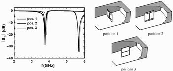
The DHR was analyzed and designed by the CST Microwave Studio applying a substrate 0.2 mm in thickness, with permittivity 2.3, loss factor 0.001, and a metal cladding 17 μm in thickness. The square substrate finally has sides, that are 6 mm in length and the outer strip is 5.25 mm in length. The transmission characteristics S 21 of the DHR located in three positions in the middle of a TEM waveguide calculated by the CST Microwave Studio are plotted in Fig. 2. The TEM waveguide cross-section is the same as the substrate, i.e., 6 × 6 mm. The resonant frequency is approximately 3.8 GHz. The ratio of the free space wavelength at resonance and the particle size is about 13, so the MTM consisting of these particles can be assumed to be a homogeneous medium. At position 1, see Fig. 2, the DHR is located perpendicular to the waveguide axis, and there is no interaction of the particle with the magnetic field. We have only one basic resonance at which the particle shows negative effective permittivity. At positions 2 and 3, see Fig. 2, the DHR is located parallel to the waveguide axis. The magnetic field now interacts with the particle, and this causes the second magnetic resonance. As shown in Fig. 3, this interaction results in negative effective permeability. This additional resonance is, however, well separated from the basic resonance aimed as the MTM working resonance. The DHR response is influenced by the position of the particle, and its behavior is anisotropic. The calculated effective permittivity of the TEM waveguide section with the DHR located at position 2 is shown in Fig. 3. Further resonant frequency reduction can naturally be achieved by increasing the substrate permittivity. For ɛ r = 2.3 the resonant frequency is around 3.8 GHz (see Fig. 2), for ɛ r = 5 it is 2.95 GHz, and finally for ɛ r = 10 it is 2.3 GHz.
Simulated transmission of the DHR located at the center of the TEM waveguide at the three positions defined at the top.

Calculated [Reference Smith, Schultz, Markos and Soukoulis11] real parts of the effective permittivity and permeability of the DHR located in the TEM waveguide in position 2.

The DHR was fabricated, see the inset of Fig. 4, on a ROGERS RT/duroid 5880 substrate with permittivity 2.22 and thickness 0.254 mm, tan δ = 0.0012 at 10 GHz, and metallization thickness 0.017 mm. The outer strip is 5.25 mm in length and 0.2 mm in width, the same as the slot width. The particle is deposited on a substrate 6 × 6 mm in area. The DHR was located in the R32 waveguide at the center of its cross-section in position 1. The corresponding measured transmission characteristic is plotted in Fig. 4. As expected, the response is weak, as we have only one tiny particle in the R32 waveguide. This fabricated particle was used in all the following experiments.
Measured transmission of the DHR located at the center of the R32 waveguide at position 1. The inset shows the fabricated DHR.

III. COUPLE OF TWO PARTICLES
It is important to know the mutual coupling mechanism between DHR resonators when designing an ENG MTM composed of them. Therefore a study was made of the transmission of a wave over two coupled particles, taking into account their different mutual positions in a waveguide. Two particular DHR resonators with resonant frequencies 3.93 and 3.96 GHz were selected for this purpose. A rectangular TEM waveguide with dimensions 15 × 7 mm was used for simulations performed in the CST Microwave Studio, whereas the R32 waveguide was used for the experiments. Figure 5 specifies the positions of the DHR planar resonators used in the first experiment. The transmission characteristics of the waveguide with the couple of the particles were studied in dependence on the changed longitudinal distance of particles y. The results of the simulations are shown in Fig. 6, and Fig. 7 shows the measured transmission. The particle resonances behave more independently as their mutual distance y grows. Finally, they become fully independent and the transmission characteristic of these two particles matches the algebraic sum of the transmission characteristic of single particles. At close distances of the particles, the lower resonance is due to the coupling moved to a lower frequency and the level of the upper resonance becomes less distinctive.
Measured particles located in their parallel positions.

Calculated transmission of the TEM waveguide with two DHR particles in dependence on longitudinal shift y defined in Fig. 5 for x = 0 mm.

Measured transmission of the R32 waveguide with two DHR particles in dependence on longitudinal shift y defined in Fig. 5, for x = 0 mm.

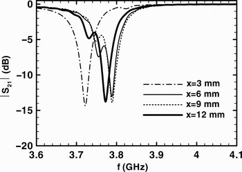
Next, a study was made of the coupling of the two DHRs located in the waveguide according to Fig. 5 depending on the lateral shift x, i.e., for y = 0. The calculated and measured transmissions are plotted in Figs 8 and 9, respectively. In dependence on the position, the dip in the transmission characteristic caused by the negative permittivity is widened, due to the mutual coupling of the particles, and at the same time shifted to higher frequencies when x is increased.
Calculated transmission of the TEM waveguide with two particles in dependence on lateral shift x defined in Fig. 5, for y = 0 mm.

Measured transmission of the R32 waveguide with two particles in dependence on lateral shift x defined in Fig. 5, for y = 0 mm.

Finally, we studied the behavior of the two particles located in a perpendicular position, as shown in Fig. 10. This couple is naturally a part of the cubic cell treated in the next paragraph. The first particle is in a position perpendicular to the waveguide side walls with the central strip in the vertical position (position 1). The second particle is oriented along the side walls of the waveguide with the central strip in the same orientation (position 2). The simulated and measured transmissions are shown in Figs 11 and 12, respectively. The particle resonant frequency declines for closer positions of the particles. Increasing the distance (parameter h) extends the frequency range of the resonance.
Measured particles at general position.

Calculated transmission of the TEM waveguide with two perpendicular particles in dependence on the movement defined in Fig. 10.

Measured transmission of the R32 waveguide with two perpendicular particles in dependence on the movement defined in Fig. 10.

The mutual coupling between resonant particles substantially influences the form of a resulting transmission characteristic. This explains the widening of the frequency band of negative permittivity noticeable in the characteristics of the cubical cell, and also the ENG MTMs presented in the following text. The second reason for widening the MTM frequency bands of negative permittivity is the spread of the particle resonant frequencies due to the non-reproducibility of the fabrication process.
IV. CUBE-LIKE UNIT CELL
DHRs were used to design a 3D isotropic unit cell which, irradiated by an electromagnetic wave, provides negative effective permittivity. This idea was carried into effect by placing the planar particles from Fig. 1(a) on the faces of a cube, creating a tetrahedral symmetrical system [Reference Baena, Jelinek, Marques and Zehentner8], see Fig. 13(a). The interior of the cube is empty, since the particle substrates themselves form the faces of the cube. Figure 13 shows three characteristic positions of the cube used in the experiments. We assume that the incident electric field is directed parallel to the y axis, z is the waveguide longitudinal axis, and the waveguide side walls are parallel to the yz plane. Basic position 1 is shown in Fig. 13(a), position 2 “on an edge” in Fig. 13(b), and position 3 “on a node” in Fig. 13(c). This unit cell was analyzed by the CST Microwave Studio only in the basic position 1. As in the case of a single DHR, the calculated transmission characteristic again shows two resonances: the lower resonance at about 4.08 GHz, providing negative effective permittivity in a frequency band tightly above it, and the higher magnetic resonance at about 5.5 GHz, providing negative effective permeability tightly above it.
A volumetric ENG cube-like cell composed of DHR: (a) position 1, (b) position 2, and (c) position 3.

The cube-like cell was fabricated by sticking planar DHR particles on polystyrene cube faces 6 × 6 × 6 mm in dimensions. The cube composed of particular DHRs is a complex system with many internal couplings, which are more intensive at smaller dimensions. These structures were studied experimentally in the R32 waveguide. The presence of waveguide walls, the existence of the TE10 mode longitudinal magnetic field component, and the non-homogeneity of this field all influence the electromagnetic response of the cell inserted in the waveguide. These effects result in different responses of the cubes in comparison with the responses of single planar particles. The transmission of the R32 waveguide with the cube-like unit cell measured when located in the waveguide center in three positions, as defined above, is shown in Fig. 14. This transmission depends only slightly on the selected position of the cube. We can therefore conclude that this cube-like unit cell has an isotropic response and is a suitable building block for an isotropic ENG MTM. This MTM will be obtained by assembling these cells in a 3D cubic periodic net.
Measured transmissions of the R32 waveguide with a cube with dimensions 6 × 6 × 6 mm assembled from six DHRs for its different positions.

V. 2D QUASI-ISOTROPIC ENG MTM COMPOSED OF DHRs
The 2D quasi-random ENG MTM was prepared as a polystyrene parallelepiped 50 × 50 mm in area cut into three slices that are equal in height of 10 mm. An equal number of DHRs is inserted periodically in the nodes of a squared net with random orientation in each slice, see Fig. 15(a). Consequently, by changing the mutual orientations of the slices in the parallelepiped by 90° rotations, we obtained 64 different parallelepipeds with randomly distributed particles inside, assuming that the vertical order of the slices is retained. For the isotropy test, the stacks of these three slices were inserted into the R32 rectangular waveguide in such a way that the two sides were parallel to the field propagation, Fig. 15(a). If the parallelepiped is isotropic and the geometry of the setup remains unchanged, the measured scattering parameters should remain invariant for each 90° rotation of the parallelepiped around its central vertical axis. The arithmetic mean value of 64 times measured S 21 is plotted in Fig. 15(b), together with its deviation.
Fabricated 2D quasi-isotropic ENG MTM (a), arithmetic mean value of the transmission through 64 parallelepipeds of the 2D ENG MTM in the R32 waveguide with 147 DHRs and its dispersion (b), σ is the standard deviation of the values.

This deviation is very small, so the MTM sample can be viewed as a 2D isotropic medium. The more the particles, the wider the stop-band in which the MTM shows negative effective permittivity.
VI. 3D ISOTROPIC ENG MTM COMPOSED OF DHRs
The current isotropic 3D mu-negative MTM with really random location of the unit cells was achieved by BC-SRRs boxed in polystyrene spherical shells filling up the volume of a cube with edges 72 mm in length, as we presented in [Reference Jelinek, Machac and Zehentner9]. The same technology was adopted here to fabricate a 3D isotropic ENG MTM using DHRs. The inset of Fig. 16 shows a disassembled shell together with the particle. The MTM specimen consisting of 256 shells with DHRs was repeatedly measured in a raised R32 rectangular waveguide, changing the position of the shells each time. The arithmetic mean value of these measurements, together with their deviation, is plotted in Fig. 16. This deviation is now bigger than the case of a 2D MTM, but it is still comparable with that obtained in [Reference Jelinek, Machac and Zehentner9] for the MTM consisting of BC-SRR. Consequently, Fig. 16 shows that the studied ENG MTM consisting of DHRs boxed in plastic spherical shells behaves as an isotropic MTM.
Arithmetic mean value and its dispersion of 25 measurements of transmission through the 3D ENG MTM in the raised R32 waveguide with 256 DHRs placed in spherical shells and randomly located in the volume of a cube with sides 72 mm in length. σ is the standard deviation of the values.

VII. CONCLUSIONS
This paper presents a new form of a double H-shaped planar resonator aimed to be primarily sensitive to the electric field of an incident electromagnetic wave. Due to intensive resonance, this particle excites negative effective permittivity. This DHR particle is small enough, and is consequently ready for application in isotropic MTMs. There is no need to use vias, as in the case of a reduced size standard electric dipole terminated by a two-loop conductor [Reference Protiva, Machac and Zehentner12]. The production of the new particle is simple and, therefore, cheap.
The DHR was designed by the CST Microwave Studio. The simulations and experiments confirm its behavior. The mutual coupling of DHRs influences their response and must be taken into account in the process of designing the MTM. Cubic-like unit cells bearing on their faces six identical DHRs with proper symmetry were proved to be suitable building blocks for a bulk isotropic ENG MTM consisting of a cubic periodic system of these cells. The concept of manufacturing bulk isotropic MTMs, both 2D with quasi-randomly distributed anisotropic particles and 3D with fully randomly distributed anisotropic particles, has also been proved practicable in the case of DHRs. In the 3D case, DHRs were boxed in polystyrene spherical shells. The frequency band of composites with randomly located unit cells is wider than the band of a single particle, and at the same time the response is more intensive.
The presented behavior of the DHR planar resonator and the ENG MTM composed of it corresponds fully to the results we have presented for BC-SRR in [Reference Jelinek, Machac and Zehentner9, Reference Zehentner and Macháč13], and the electric dipole terminated by inductors in [Reference Protiva, Machac and Zehentner12, Reference Zehentner and Macháč13]. A left-handed MTM can be obtained by combining particles showing negative permeability – BC-SRR together with particles showing negative permittivity – DHR or electric dipoles both boxed in plastic spherical shells. Such a mixture poured into a volume of any shape represents a homogeneous MTM with an isotropic response.
ACKNOWLEDGEMENT
This work has been supported by the Grant Agency of the Czech Republic under project no. 102/09/0314.
 Michal Blaha was born in Prague, Czech Republic, in 1981. He received the Ing. degree in Radio Engineering from Czech Technical University in Prague, Czech Republic, in 2008.
 Jan Machac is with the Faculty of Electrical Engineering, Czech Technical University in Prague. Currently, he is an Associate Professor of Electrical Engineering. His main research interests are metamaterials, modeling of planar passive elements and subsystems used in millimeter-wave techniques, and field theory. He is an author or co-author of more than 180 papers in scientific journals and conferences. He is a senior member of the IEEE. He was a member of the Technical Program Committee of the European Microwave Conference in 1995–1997, and was Conference Secretary in 1996. He was a member of the TPC of the 2004 URSI International Symposium on Electromagnetic Theory, and presently is a member of the IEEE MTT International Microwave Symposium TPC.