
I. INTRODUCTION
It is well known that enhanced fatigue properties are the safety guarantees for the long-time service of structural materials. Reference Suresh1 In the early studies, Reference Suresh1,Reference Tóth and Yarema2 researchers indicated that the fatigue limit is proportional to the ultimate tensile strength (UTS); in other words, strengthening is an effective method to improve the fatigue property. On the other hand, the tensile strength of advanced structural materials has been promoted to a very high level with the improvement of different strengthening mechanisms, e.g., the ultra-high strength steels (UHSS) to almost 3 GPa. Reference Aggen, Akstens, Allen, Avery, Babu and Bayer3 But the fatigue properties are not improved at the same time as expected, and a part of them even exhibit the lowering fatigue properties. Reference Lee, Pan, Hathaway and Barkey4–Reference Garwood, Zurburg and Erickson6 Pang et al. Reference Pang, Li, Wang and Zhang7 have pointed out that fatigue limits showed a parabolic change with the increase of UTS, which has been verified in large number of alloys. Since the loss of fatigue limit is inevitable with strengthening the material, whether the traditional methods are still valid or not for improving the fatigue properties of materials with very high strength?
To answer the question above, the UHSS has been selected for this study. The maraging steels, as one kind of UHSS, can possess unique combinations of very high strength and excellent toughness by adding several kinds of alloying elements. Reference Aggen, Akstens, Allen, Avery, Babu and Bayer3,Reference Habiby, Siddiqui, Hussain, Khan, ul Haq and Khan8–Reference Vasudevan, Kim and Wayman11 Maraging steels can be effectively strengthened after aging treatment, and its strength belongs to the highest level (∼2.7 GPa) in different kinds of steels Reference Aggen, Akstens, Allen, Avery, Babu and Bayer3,Reference He, Yang, Qu, Kong and Su12–Reference Hussain, Tauqir, ul Haq and Khan14 ; its toughness is relatively higher than other steels in the same strength level. Reference Decker, Eash and Goldman15 However, when the maraging steels are further strengthened through optimizing their composition and heat treatment techniques, their toughness is unfortunately dropped to a low level, Reference Rack and Kalish16 and their fatigue strength is found to be far below the expected value, which is usually empirically predicted by taking half of the UTS of steels. Reference Wang, Yan, Duan, Shan, Zhang and Yang13 Especially for the components with a complicated shape, the notch effect should be investigated under cyclic loading; it is significantly important to investigate the notch fatigue properties of these materials with ultra-high strength.
The fatigue properties of maraging steels are normally improved by reducing the content of those elements, while it will be harmful to the fatigue properties. Reference Hussain, Tauqir, ul Haq and Khan14,Reference Lee, Jang, Kuk and Kim17 For the fixed composition, those surface strengthening methods, such as shot peening, are considered as the most effective methods to improve the fatigue properties of the materials. Reference Peyre, Fabbro, Merrien and Lieurade18–Reference Zhang and Lindemann20 Normally, the increased surface smoothness Reference Zhang and Lindemann20 and residual compressive stress Reference Farrahi, Lebrijn and Couratin21 caused by shot peening can effectively improve the resistance to the nucleation of surface fatigue cracks, thereby slowing the higher fatigue life of the material. Except for the surface strengthening, shot peening can also induce the varying microstructures from the surface to interior of the specimen, which can be considered as another effective influencing factor for the improvement of fatigue properties. In a previous study, it has been shown that the stress gradient can block the propagation of fatigue cracks from the surface to the interior under torsion fatigue Reference Li, Zhang, Zhang and Zhang22 ; this effect can be caused by the microstructure gradient in shot-peened materials. On the other hand, the stress required for the nucleation of fatigue cracks is elevated with strengthening the material, and the crack blunting becomes much easier in materials with good ductility. Reference Roland, Retraint, Lu and Lu23 Therefore, after shot peening, the highly strengthened surface can resist the nucleation of fatigue cracks, and inside the sample, the fatigue crack propagation is slown down due to its higher ductility.
The above analysis is reasonable and is mainly based on the surface hardening effect. When the material is strengthened to a very high level, it will become very difficult to further harden the surface of the material by shot peening. But there is a lack in understanding the fatigue properties of materials after shot peening. However, no related theoretical analysis has been proposed. Therefore, the notch fatigue specimens of maraging steels will be processed by shot peening and then the change of fatigue performance and related influencing factors will be compared.
II. EXPERIMENTAL PROCEDURE
The composition of selected maraging steel (CM400) is 18% Ni, 15% Co, 8% Mo, and 2% Ti by weight, and the content of carbon is less than 0.003%. It was melted in a 300 kg vacuum induction melting furnace at first and then was remelted in a vacuum arc melting furnace. After homogenization at 1250 °C for 24 h, the ingot was rolled to a cross-section dimension of 55 × 55 mm, which was finally forged into rods of 22 mm in diameter followed by air cooling. Then the specimens for the tests were cut from the middle part of the forged rods, and those for tensile and fatigue tests were cut with the loading direction in accordance with the rolling direction. All of those specimens were solution treated at 820 °C for 1 h followed by a cryogenic treatment in liquid nitrogen for 1 h to remove the retained austenite and then were aged at different temperatures and times.
After aging treatment, those specimens for microstructure observation and microhardness test were mechanically ground and polished. Part of the fatigue specimens were shot peened with particles of 0.4 mm in diameter under a pressure of 0.2 MPa. Fatigue tests were performed by using a PLG-100C electromagnetic resonant high-frequency fatigue testing machine (Changchun Research Institute for Mechanical Science Co. Ltd., Changchun, China). The microhardness was measured with a load of 500 g and loading time of 13 s by an MH-3 Digital Vickers hardness testing machine (Shanghai Everone Precision Instrument Co. Ltd., Shanghai, China). Tensile specimens with a gauge size of 4 × 3 × 23 mm were carried out by an Instron 8801 testing machine (ITW Instron Co. Ltd., London, United Kingdom) at a strain rate of 1 × 10⁻³/s, and each result was taken from an average of three tests. For the fatigue test, the frequency was 113 Hz with a sine wave, and the stress ratio was 0.1. The fatigue specimen with a gauge size of ϕ10 × 75 mm was notched in the middle, and the notch depth was 2 mm. All the tests were conducted at room temperature in air.
The microstructure of the specimens after peak-aging treatment was examined under Cambridge S360 scanning electron microscopy (SEM; Cambridge Instruments, Birmingham, United Kingdom) and Tecnai G2 20 transmission electron microscopy (TEM; FEI Company, Hillsboro, Oregon) after being etched by 10% nital solution. The roughness of the specimens was measured using LEXT OLS4000 laser confocal microscope (LCM; Olympus Corporation, Tokyo, Japan) before and after shot peening. The notch geometry of the fatigue specimens was observed before and after shot peening using a Keyence VHX-1000E digital microscope (Keyence Corporation, Osaka, Japan). And the fracture morphologies were observed after the fatigue test on a SEM.
III. EXPERIMENTAL RESULTS
A. Microstructures of CM400 maraging steel
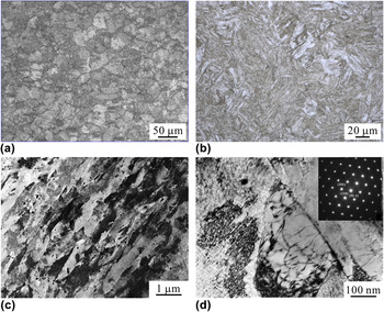
The microstructures of CM400 maraging steel were observed using OM and TEM, as shown in Fig. 1. The equiaxed grains covered the whole specimen, which can be observed from Fig. 1(a). These grains did not grow to a very large size; the grain size is about 20–50 μm. This character mainly depends on their heat treatment history, and the solid-solution temperature is not enough to induce a prominent increase of the grain size. The microstructures of the matrix consist of lath martensite, and no obvious precipitated phase or retained austenite can be observed, as shown in Fig. 1(b). Related width of the lath martensite measured by TEM [shown in Fig. 1(c)] is about 100–500 nm. The further magnified area [shown in Fig. 1(d)] shows that lots of dislocations were kept within the lath, and the “tweed pattern”-modulated structure could be observed.
Microstructures of original maraging steel observed by OM and TEM: (a) equiaxed grains; (b) lath martensite; (c) lath martensite; (d) dislocations and “tweed pattern”-modulated structure.

B. Tensile properties, hardness and notch fatigue properties
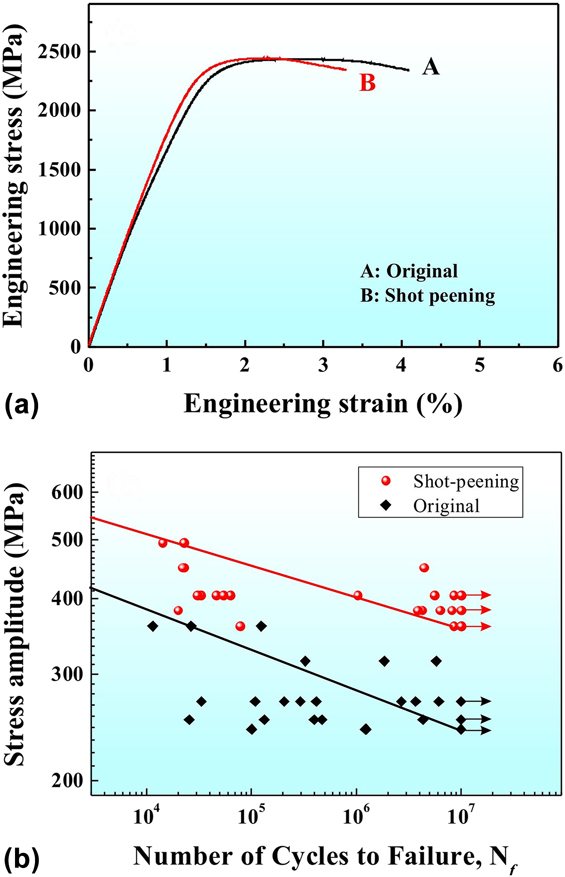
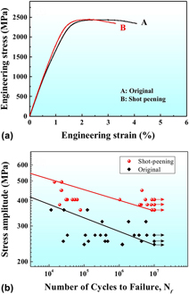
Figure 2(a) is the tensile stress–strain curves of CM400 steel before and after shot peening. The UTS is not varied, but the elongation is slightly decreased after shot peening. The yield strength is increased by about 140 MPa, which indicates that the surface has been strengthened. But this strengthening effect is quite weak, it only delayed the beginning of the plastic deformation, while it did not affect the initiation of plastic instability.
(a) Tensile stress–strain curves and (b) S–N curves of notch fatigue tests before and after shot peening.

To further study the surface strengthening effect, the Vickers hardness (HV) was measured before and after shot peening. It is found that the hardness is almost not changed by shot peening, both of them are slightly higher than 7.1 GPa. Because the low work-hardening ability can be found from the tensile stress–strain curve, the UTS can be calculated by one third of HV Reference Zhang, Li and Zhang24 and is a little lower than 2400 MPa, which is consistent with the tensile results. On the contrary, the hardness is not changed before and after shot peening, which can be attributed to their similar tensile properties.
The fatigue life is scattered under a fixed stress amplitude. Here, we use the logarithmic middle value between the minimum and maximum fatigue life to plot the S–N curves before and after shot peening, as shown in Fig. 2(b). It is found that the fatigue limit is obviously elevated and the stress amplitude is increased from 243 to 360 MPa, i.e., the maximum stress increases from 540 to 800 MPa. The Basquin relationship was drawn using the fatigue life with a 50% survival rate, shown as solid line in Fig. 2(b). The Basquin relationship can be described by following equation, Reference Suresh1
 $${\sigma _{\rm{a}}} = {\sigma '_{\rm{f}}} \cdot {\left( {2{N_{\rm{f}}}} \right)^b}\quad ,$$
where, σa is the stress amplitude,
 ${\sigma '_{\rm{f}}}$
is the fatigue strength coefficient, N
f is the number of cycles to failure, and b is the fatigue strength exponent.
According to this formula,
 ${\sigma '_{\rm{f}}}$
and b can be calculated based on the experimental results.
 ${\sigma '_{\rm{f}}}$
equals to 756 and 839 MPa before and after shot peening, respectively. In the previous publication, the increased
 ${\sigma '_{\rm{f}}}$
is generally attributed to the improvement of UTS,
Reference An, Wu, Wang and Zhang25,Reference Zhang, An, Zhang, Yang, Yang, Wu and Zhang26
but UTS is not changed by shot peening in this research. It should be related to the yield strength, which is increased by about 140 MPa after shot peening. This is because the specimen was mainly cyclically deformed in the elastic stage, and only some locations suffered to the slightly plastic deformation due to the inhomogeneity of the microstructure. b, which can represent the fatigue damage rate,
Reference Li, Zhang, Zhang and Zhang22,Reference An, Wu, Wang and Zhang25
equals to −0.068 and −0.051 before and after shot peening, respectively, i.e., shot peening can slightly decrease the fatigue damage rate. Therefore, it can be concluded that both
 ${\sigma '_{\rm{f}}}$
and b are increased by shot peening, and the notch fatigue properties of maraging steels is enhanced.
C. Surface morphologies, notch geometry and residual stress
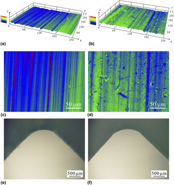
Surface morphologies were observed by LCM, as shown in Figs. 3(a)–3(d), and related roughness was measured at the same time. The roughness is increased from 0.168 to 0.301 μm after shot peening, which is consistent with the shot peening results with high energy. Reference Zhang and Lindemann20 However, further observation of surface morphologies showed lots of transversal machining traces in the original material, as shown in Figs. 3(a) and 3(c). While these traces are significantly reduced after shot peening, lots of chip-liked morphologies can be observed, as shown in Figs. 3(b) and 3(d). Although the increased roughness is caused by those small chip-liked morphologies against the promotion of high-cycle fatigue property, the changed morphologies will lower the fatigue damage tendency than those in the transversal machine trace. Therefore, the morphologies of surface are more important than the measured roughness value.
Surface morphologies before (a, c) and after (b, d) shot peening observed by LCM and notch geometry before (e) and after (f) shot peening.

Besides, to avoid the effect of the notch shape, the geometry of the notch was measured before and after shot peening, as shown in Figs. 3(e) and 3(f). It is found that there is no difference between the two specimens, thus the factor of stress concentration (K t) should be the same.
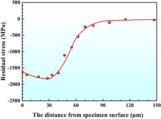
Normally, the residual stress induced by shot peening was thought as the main reason for the improved fatigue strength. Thus, the residual stress with increasing the depth from the specimen surface was measured, as shown in Fig. 4. It can be seen that the maximum residual compressive stress is about 1800 MPa, and the depth with residual compressive stress is about 70 μm. If the tensile strain in the cross section is proposed as the equal value, the fatigue strength can only be improved by about 40 MPa, which is not large enough to induce the improved fatigue strength obtained.
The residual stress with the depth from the specimen surface after shot peening.

D. Fatigue fracture morphologies before and after shot peening
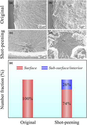
After fatigue tests, the fracture surfaces were observed for specimens before and after shot peening, as shown in Figs. 5(a)–5(d), respectively. Without shot peening, the fatigue cracks always nucleated from the surface of the specimens, and the typical characters of the fatigue crack initiation site are shown in Figs. 5(a) and 5(b). These fatigue cracks may be mainly induced by the transversal machine traces, which have been shown in Fig. 5(a). On the other hand, the fatigue propagation and final rupture regions are mainly formed by the transgranular fracture mode. After shot peening, the fatigue crack initiation sites are partly moved to the subsurface or interior of the specimens, as shown in Figs. 5(c) and 5(d). These fatigue cracks initiated from two kinds of inclusions, i.e., nonmelted matrix and aluminum oxide, which are confirmed using SEM energy spectrum analysis. The fatigue cracking propagation and final rupture are also formed by the transgranular mode. To clearly describe the different fatigue cracking behaviors before and after shot peening, the statistical results of the initiation sites of fatigue cracks are shown in Fig. 5(e). The fatigue cracks are nucleated from the subsurface or from the interior within 26% of specimens. That can be explained by resisting fatigue cracking in the strengthened surface. Even under the situation of surface cracks, the fatigue properties should also be elevated due to the hardened surface.
Fracture surface of original and shot-peened specimen: (a, b) fatigue source at surface of specimen; (c) subsurface or (d) interior of the specimen and statistic results of nucleation sites of fatigue cracks; (e) statistic results of nucleation sites of fatigue cracks.

IV. DISCUSSION
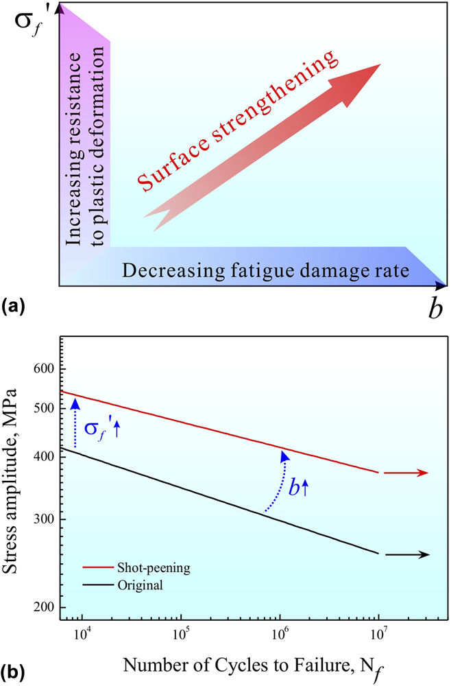
Based on the above results, the notch fatigue properties of maraging steels can be effectively enhanced by shot peening. There are two parameters,
 ${\sigma '_{\rm{f}}}$
and b, which can be used to analyze the fatigue damage behavior, as shown in Fig. 6.
 ${\sigma '_{\rm{f}}}$
is related to the yield strength of the material, i.e., increasing the resistance to plastic deformation can elevate
 ${\sigma '_{\rm{f}}}$
. b represents the fatigue damage rate, but the influencing factors are not clear. Shot peening, as one of the surface strengthening methods, can increase
 ${\sigma '_{\rm{f}}}$
and b simultaneously, thereby promoting its fatigue limit. To clearly understand the mechanisms of enhanced fatigue properties by shot peening, the fatigue failure process and related effects are discussed in the following.
(a) Schematic illustration of the approach to enhance fatigue properties by shot peening; (b) effects of fatigue strength coefficient and exponent.

A. The general process of fatigue failure
During cyclic deformation, materials generally fracture at a stress lower than their tensile strength. Especially for high-cycle fatigue tests, the applied maximum stress is normally lower than the yield strength. The previous publication Reference Suresh1 has pointed out that fatigue failure is mainly caused by localized deformation. Even if the specimen elastically deformed at the macroscopic scale, plastic deformation perhaps occurred at some locations. However, the reasonable fatigue damage process has not been proposed up to now.
Based on the energy consideration of the fracture of bulk metallic glasses, the elastic deformation will be ended when the imported energy is equal to the shear fracture energy or the critical dilatation energy. Reference Liu, Qu and Zhang27 For ductile materials, the inputted energy can also be resolved to the shear work and dilatation work. The shear work can induce a dislocation slip to cause the plastic deformation, while the dilatation work is induced by the hydrostatic stress, which cannot cause plastic deformation. Once the dilatation work reaches the critical value, fracture will take place. The different effects of shear and dilatation work will be discussed below.
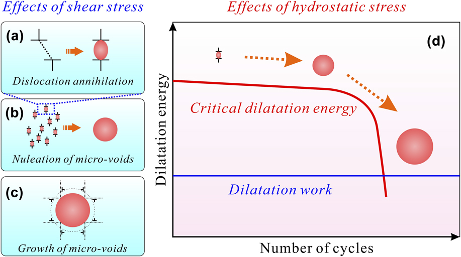
For ductile materials, the shear work is easily transferred to the plastic work by driving the slipping of dislocations. Even if the specimen is deformed at the elastic stage, the dislocations can also move at some locations. With increasing the number of cycles, the high dislocation density will lead to the formation and growth of microvoids due to the annihilation, as schematically shown in Figs. 7(a)–7(c). Firstly, dislocation dipoles will be formed easily under cyclic deformation. Reference Li, Li, Wang and Zhang28 When the dislocation density is high enough, the dipoles will annihilate to nucleate groups of vacancies, Reference Li, Zhang, Zhang, Wang and Zhang29 as shown in Fig. 7(a). These groups of vacancies further coalesce with each other, leading to the nucleation of microvoids, as shown in Fig. 7(b). Finally, the microvoids will continuously grow by emitting dislocations from their surface. Reference Lubarda, Schneider, Kalantar, Remington and Meyers30 Therefore, the shear work induced the plastic deformation and the related localized microscopic damage.
Schematic illustration of the general process of fatigue failure: (a–c) effects of shear stress; (d) effect of hydrostatic stress.

Normally, the dilatation process is mainly determined by elongating the distance between two neighbor atoms, which is similar to the elastic deformation process. Thus the dilatation fracture energy is mainly used to form the fracture surface, i.e., it mainly consists of the surface energy. Considering the change of the fracture surface, it is proposed that the critical dilatation energy is almost not changed by varying the microstructures, while it slightly decreases by the nucleation of microvoids. After the microvoids grow to the critical value, the critical dilatation energy should be dramatically dropped. When the internal damage is serious enough, the critical dilatation energy is lower than the dilatation work caused by the hydrostatic stress, then the fatigue fracture will be nucleated, as shown in Fig. 7(d).
In one word, the shear stress may slowly change the state of materials cycle by cycle, while the hydrostatic stress causes the final fracture when the critical dilatation energy is low enough. Therefore, the fatigue damage rate can be decreased by lowering the shear stress or by raising the yield strength. But the critical dilatation energy is hard to be improved, thus the fatigue damage tolerance can only be increased by lowering the hydrostatic stress.
B. Notch effect on hydrostatic and shear stress
Following the analysis above, the maximum shear stress and hydrostatic stress will be analyzed in the notched specimen. Firstly, the three principle stresses along the fracture surface can be approximately given as Reference Qu, Zhang and Zhang31,Reference Timoshenko and Goodier32
 $${\sigma _x} = {3 \over 2}{\sigma _{{\rm{nss}}}}\left( {{{{r^2}} \mathord{\left/ {\vphantom {{{r^2}} {{x^2}}}} \right. \kern-\nulldelimiterspace} {{x^2}}} - {{{r^4}} \mathord{\left/ {\vphantom {{{r^4}} {{x^4}}}} \right. \kern-\nulldelimiterspace} {{x^4}}}} \right)\quad ,$$
 $${\sigma _y} = {{{\sigma _{{\rm{nss}}}}\left( {{{2 + {r^2}} \mathord{\left/ {\vphantom {{2 + {r^2}} {{x^2}}}} \right. \kern-\nulldelimiterspace} {{x^2}}} + {{3{r^4}} \mathord{\left/ {\vphantom {{3{r^4}} {{x^4}}}} \right. \kern-\nulldelimiterspace} {{x^4}}}} \right)} \mathord{\left/ {\vphantom {{{\sigma _{{\rm{nss}}}}\left( {{{2 + {r^2}} \mathord{\left/ {\vphantom {{2 + {r^2}} {{x^2}}}} \right. \kern-\nulldelimiterspace} {{x^2}}} + {{3{r^4}} \mathord{\left/ {\vphantom {{3{r^4}} {{x^4}}}} \right. \kern-\nulldelimiterspace} {{x^4}}}} \right)} 2}} \right. \kern-\nulldelimiterspace} 2}\quad ,$$
 $${\sigma _z} = \nu \left( {{\sigma _x} + {\sigma _y}} \right)\quad ,$$
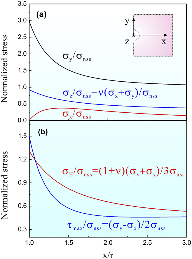
where σnss is the net stress or the nominal stress; r is the notch radius; x is the distance away from the center of the notch tip circle [see the inset sketch in Fig. 8(a)]; ν is the Poisson’s ratio. According to Eqs. (2a)–(2c), the variations of three principle stresses with distance x can be plotted in Fig. 8(a). Both σ y and σ z are continuously decreased far away from the notch tip, while σ x is increased from 0 to the maximum value and then decreased.
(a) Three principle stresses and (b) maximum shear stress and hydrostatic stress distribution far away from the notch tip along the x direction.

The hydrostatic stress, σH, and maximum shear stress, τmax, can be written by the three principle stresses, Reference Xie, Lin and Ding33
 $${\sigma _{\rm{H}}} = {{\left( {{\sigma _x} + {\sigma _y} + {\sigma _z}} \right)} \over 3} = {{\left( {1 + \nu } \right)\left( {{\sigma _x} + {\sigma _y}} \right)} \over 3}\quad ,$$
 $${\tau _{\max }} = {{\left( {{\sigma _y} - {\sigma _x}} \right)} \mathord{\left/ {\vphantom {{\left( {{\sigma _y} - {\sigma _x}} \right)} 2}} \right. \kern-\nulldelimiterspace} 2}\quad .$$
Considering Eqs. (2a), (2b), (3a), and (3b) together, the variations of hydrostatic stress and the maximum shear stress with distance x can be plotted in Fig. 8(b). It can be found that both σH and τmax are decreased far away from the notch tip. But τmax is decreased more quickly in the initial stage and is almost unvaried when x > 1.75r.
After shot peening, the yield strength of the materials was improved due to the strengthened surface. Thus the plastic deformation of the specimen surface became more difficult. As a result, part of the specimens fractured at the subsurface or at the interior of the specimens. Based on the above analysis, both σH and τmax are decreased when the fatigue crack initiation site changed from surface to subsurface/interior of the specimen. It means that the fatigue damage tolerance will be increased, while the fatigue damage rate will be decreased after shot peening. Even if the fatigue cracks nucleated from the surface, the improved yield strength and residual stress induced by shot peening can also decrease the fatigue damage rate. That is the reason why the fatigue properties can be effectively improved by shot peening.
V. CONCLUSION
The notch fatigue properties of maraging steels can be effectively enhanced by the shot peening process. Based on the results and analysis, the conclusions can be given as follows:
-
(1) The tensile strength and hardness did not vary so much, while the fatigue limits are obviously improved. Meanwhile, the surface roughness is not the crucial factor for fatigue properties, while the surface morphology is more important in improving the fatigue limit of ultra-high strength steel.
-
(2) With the Basquin equation, the fatigue strength coefficient,
 ${\sigma '_{\rm{f}}}$
, and the fatigue strength exponent, b, can be elevated simultaneously by shot peening. And
${\sigma '_{\rm{f}}}$
is related to the resistance of plastic deformation.
-
(3) The fatigue process can be resolved to two parts: the first one is the slowly damage process induced by shear stress, which is related to the fatigue damage rate; the second one is the final failure caused by the dilatation fracture, which is corresponding with the fatigue damage tolerance.
-
(4) Shot peening can effectively resist the fatigue cracks nucleating at the surface. When the nucleation sites were changed to the subsurface/interior, both the maximum shear stress and hydrostatic stress are decreased, i.e., the fatigue damage rate was decreased while the fatigue damage tolerance was increased. Thus the fatigue limit was effectively enhanced after shot peening.


ACKNOWLEDGMENTS
The authors would like to thank Dr. W. Wang, H.H. Su for materials preparation, SEM observations. This work was financially supported by the National Natural Science Foundation of China (NSFC) under grant Nos. 51331007 and 51301179.