



1. Introduction
The geological sequestration of large volumes of
 $\text{CO}_{2}$
into subsurface aquifers and depleted oil and gas fields has been advocated by the IPCC (2005) as a means of reducing atmospheric emissions of
 $\text{CO}_{2}$
. A key challenge for this technology concerns the modelling of the long-term fate of the
 $\text{CO}_{2}$
. Following injection into the subsurface, one may envisage that a plume of
 $\text{CO}_{2}$
develops and migrates upwards until reaching a structural trap where it may accumulate (Pruess et al.
Reference Pruess, Xu, Apps and García2003; Hesse, Tchelpi & Orr Reference Hesse, Tchelpi and Orr2008), although some of the
 $\text{CO}_{2}$
may dissolve into the groundwater (Lindeberg & Wessel-Berg Reference Lindeberg and Wessel-Berg1997; Riaz et al.
Reference Riaz, Hesse, Tchelepi and Orr2006; Ennis-King & Paterson Reference Ennis-King and Paterson2007; Pau et al.
Reference Pau, Bell, Pruess, Almgren and Lijenski2009) or become capillary trapped (Bennion & Bachu Reference Bennion and Bachu2008; Hesse et al.
Reference Hesse, Tchelpi and Orr2008; Farcas & Woods Reference Farcas and Woods2009; Woods Reference Woods2015) en route to the trap. The
 $\text{CO}_{2}$
which accumulates in a structural trap may then gradually dissolve into the underlying groundwater; this represents an important step in the long-term stability of the sequestered
 $\text{CO}_{2}$
, and has attracted much scientific investigation (Pruess et al.
Reference Pruess, Xu, Apps and García2003; Riaz et al.
Reference Riaz, Hesse, Tchelepi and Orr2006; Hewitt, Neufeld & Lister Reference Hewitt, Neufeld and Lister2013). Since the
 $\text{CO}_{2}$
-saturated water is relatively dense, convective flows can develop, with unsaturated water rising towards the
 $\text{CO}_{2}$
interface, replacing the dense
 $\text{CO}_{2}$
-saturated water, thereby promoting convective dissolution. Various models have been developed to quantify the flux associated with such convective dissolution since it may be one of the key rate-limiting steps. As one end-member, the dissolution may develop in a deep, permeable layer in which a convective mixing flow develops (figure 1) (Riaz et al.
Reference Riaz, Hesse, Tchelepi and Orr2006). The
 $\text{CO}_{2}$
-saturated and unsaturated water then mix until the whole depth of the water in the aquifer below the
 $\text{CO}_{2}$
pool has become saturated in
 $\text{CO}_{2}$
and the convection shuts off (Hewitt et al.
Reference Hewitt, Neufeld and Lister2013). Analyses have been carried out to explore the role of heterogeneity and background flows in such convective dissolution (Kuznetsov & Nield Reference Kuznetsov and Nield2011, Reference Kuznetsov and Nield2012; Ranganathan et al.
Reference Ranganathan, Farajzadeh, Bruining and Zitha2012). As an idealised limit, in an isotropic formation of effective permeability
 $k$
and with a density contrast between unsaturated groundwater and
 $\text{CO}_{2}$
-saturated groundwater,
 ${\rm\Delta}{\it\rho}$
, plumes typically descend with Darcy velocity
 $$\begin{eqnarray}u=\frac{k{\rm\Delta}{\it\rho}g}{{\it\mu}},\end{eqnarray}$$
where
 ${\it\mu}$
is viscosity and
 $g$
acceleration due to gravity, and this may have value of order
 $10^{-8}{-}10^{-9}~\text{m}~\text{s}^{-1}$
. We infer that provided there is a source of unsaturated water, then with
 $\text{CO}_{2}$
concentration of 1–3 wt% following dissolution into the water, the trapped plume of
 $\text{CO}_{2}$
may dissolve into the underlying fluid at a rate determined by the speed of convective plumes times this solubility, leading to an estimate of
 $100{-}1000~\text{kg}~\text{CO}_{2}~\text{m}^{-2}$
per thousand years. Trapped pockets of
 $\text{CO}_{2}$
may therefore dissolve over thousands of years (Riaz et al.
Reference Riaz, Hesse, Tchelepi and Orr2006; Woods & Espie Reference Woods and Espie2012).
(a) An illustration of the convective dissolution within the upper aquifer, which leads to
 $\text{CO}_{2}$
saturation of the formation fluid in the upper aquifer. (b) An illustration of the larger-scale flow domain showing the anticline or fold which traps the
 $\text{CO}_{2}$
plume in the upper aquifer. Also shown are the fractures connecting the upper and lower aquifers. The greater density of the
 $\text{CO}_{2}$
-saturated formation water, coupled with any pressure difference between the aquifers, relative to the hydrostatic pressure difference, leads to possible counterflow and hence supply of undersaturated fluid to the upper aquifer.

Once the fluid below the structural trap has become saturated in
 $\text{CO}_{2}$
, unsaturated water from more distal locations is required to continue the dissolution process. If the aquifer is of limited vertical extent, but has a shallow inclination, then a convective exchange flow may develop between the unsaturated water in the laterally distant parts of the aquifer and the
 $\text{CO}_{2}$
-saturated water below the structural trap, providing a source of fresh water for the dissolution (figure 1) (Woods & Espie Reference Woods and Espie2012). Owing to the very small speed, the near-horizontal current of unsaturated water migrating towards the structurally trapped plume of
 $\text{CO}_{2}$
may require tens to hundreds of thousands of years to dissolve the
 $\text{CO}_{2}$
, and eventually the flow may become controlled by shear-dispersion (Szulczewski, Hesse & Juanes Reference Szulczewski, Hesse and Juanes2014).
Although the above models provide end-members for the rate of convection-driven dissolution, they are based on a picture of a single reservoir within an impermeable country rock. Many sedimentary rocks are composed of a series of laterally extensive and relatively thin layers, with shale barriers or more extensive layers of siltstone which restrict cross-layer flow. One may therefore envisage a third scenario in which there are stacked sedimentary layers, each tens of metres thick and separated by nearly impermeable siltstone or shale layers, ranging from metres to tens of metres in thickness, forming a highly layered system (Phillips Reference Phillips1991). The seal rock may become fractured following emplacement owing to compaction, folding or other tectonic processes. Such fractures may then provide a pathway between neighbouring aquifers, and hence a source of additional unsaturated water which may enhance the
 $\text{CO}_{2}$
dissolution process (figure 1
b).
The purpose of this work is to explore the vertical convective exchange associated with such fractures between two aquifers. In the context of
 $\text{CO}_{2}$
sequestration, relatively dense
 $\text{CO}_{2}$
-saturated brine would form directly below a
 $\text{CO}_{2}$
plume as a result of convective dissolution (e.g. Lindeberg & Wessel-Berg Reference Lindeberg and Wessel-Berg1997; Ennis-King & Paterson Reference Ennis-King and Paterson2007). If there is a deeper aquifer which contains less-dense brine, undersaturated in
 $\text{CO}_{2}$
, then ultimately, following the injection phase, this may develop a convective exchange flow along the fractures with the
 $\text{CO}_{2}$
-saturated water. We note that during the
 $\text{CO}_{2}$
injection phase, the system is likely to be overpressured, and any fractures may initially be filled with the
 $\text{CO}_{2}$
-saturated brine from the upper aquifer. However, following the end of the injection phase, as the system decompresses, and the flows become dominated by buoyancy forces, then an upward rising localised plume may develop in one or more fractures, owing to the buoyancy of the lower aquifer fluid relative to the
 $\text{CO}_{2}$
-saturated fluid in the upper aquifer. Such plumes lead to an exchange of fluid in the fracture, with the heavier
 $\text{CO}_{2}$
-saturated brine in the fracture descending to the lower aquifer. As some of these plumes rise upwards in the fractures, one can envisage the development of a convective exchange between the two aquifers, as we have observed in our experiments (§ 3). The main focus of this paper is to describe the different patterns of steady convective flow which may develop in a multiply fractured seal layer after the transient development of the flow, which depends in detail on the initial conditions, although we also discuss the counterflow which may develop in a single, laterally extensive fracture (Tartakovsky & Meakin Reference Tartakovsky and Meakin2005; Chen & Zhang Reference Chen and Zhang2010).
Once an exchange flow is established, it may then supply
 $\text{CO}_{2}$
-undersaturated water to the upper aquifer leading to continuing dissolution of the
 $\text{CO}_{2}$
. By quantifying the flux, we can assess its magnitude and importance in dissolving the
 $\text{CO}_{2}$
plume relative to the lateral exchange flow which brings unsaturated water from laterally distant parts of the formation (figure 1
b) (Woods & Espie Reference Woods and Espie2012).
In our modelling, we assume that the density of the fluid in the upper aquifer is greater owing to the dissolution of
 $\text{CO}_{2}$
into the water in this aquifer. Provided this leads to the density of the fluid in this upper aquifer exceeding that in the lower aquifer then the convective exchange flow described herein can develop, even if prior to the injection and dissolution of
 $\text{CO}_{2}$
, the fluid in the lower aquifer was initially denser than that in the upper aquifer owing for example to compositional differences. In this context, we note that there is a more general set of exchange flow processes which may lead to groundwater mixing in situations in which unstable buoyancy gradients develop (Flowers & Hunt Reference Flowers and Hunt2007). Indeed, if two aquifers are initially isolated, and the fluid in the upper aquifer is of greater composition and hence density, then if a series of faults open up to connect the aquifers, for example following a tectonic event, exchange flows analogous to those discussed in this work may develop. However, it is also possible that the fluid in the lower aquifer is more dense, and in this case, the buoyancy forces tend to suppress convective exchange between the aquifers. In that case there may be some initial pressure-driven exchange flow, but as the pressure difference between the two aquifers decreases, such flows will become suppressed by the stabilising effect of buoyancy.
2. Model system
We model a system in which the geological strata includes an impermeable stratigraphic horizon of vertical extent
 $h$
separating an upper and lower permeable layer. We envisage that there is a structural trap of
 $\text{CO}_{2}$
and that owing to convective dissolution of the
 $\text{CO}_{2}$
, the water directly below the
 $\text{CO}_{2}$
plume is
 $\text{CO}_{2}$
saturated with density
 ${\it\rho}+{\rm\Delta}{\it\rho}$
, while the formation water in the lower layer is unsaturated and has density
 ${\it\rho}$
(figure 1). We also assume that the two permeable regions are connected by
 $m$
parallel fractures, with permeability
 $k_{i}$
and aperture of width
 $d_{i}$
,
 $i=1,\dots ,m$
, located around the anticline structure.
We now show that depending on the pressure difference between the aquifers, this density contrast can drive a steady convective exchange flow through the fractures. To illustrate the phenomenon, we assume that the fluid in the upper aquifer has constant density
 ${\it\rho}+{\rm\Delta}{\it\rho}$
and that in the lower aquifer has constant density
 ${\it\rho}$
. Also we assume the resistance to flow is much greater in the fractures than the aquifer, so that the pressures in the upper and lower aquifers are each approximately uniform (see below). In this case, if the pressure in the lower layer,
 $p_{l}$
, exceeds the hydrostatic pressure of the light fluid in the fracture plus the pressure of the upper layer,
 $p_{u}$
, by an amount
 ${\rm\Delta}p$
where
 $0<{\rm\Delta}p<{\rm\Delta}{\it\rho}gh$
so that
 $p_{l}=(p_{u}+{\it\rho}gh)+{\rm\Delta}p$
then downflow or upflow can occur in the different fractures since the pressure in the lower layer is not sufficient to balance a fracture full of the dense upper layer fluid, but is more than sufficient to balance a fracture full of the light lower layer fluid. Without loss of generality, we label the fractures with downflow (
 $d$
) as
 $i=1,\dots ,n$
and those with upflow (
 $u$
) as
 $i=n+1,\dots ,m$
. The total downflow and upflow volume fluxes per unit length along the fractures are then given by
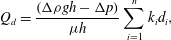 $$\begin{eqnarray}\displaystyle & Q_{d}=\displaystyle \frac{\left({\rm\Delta}{\it\rho}gh-{\rm\Delta}p\right)}{{\it\mu}h}\mathop{\sum }_{i=1}^{n}k_{i}d_{i}, & \displaystyle\end{eqnarray}$$
 $$\begin{eqnarray}\displaystyle & Q_{u}=\displaystyle \frac{\left({\rm\Delta}p\right)}{{\it\mu}h}\mathop{\sum }_{i=n+1}^{m}k_{i}d_{i}, & \displaystyle\end{eqnarray}$$
 $\text{CO}_{2}$
-saturated fluid. In figure 2(a), we illustrate the magnitude of the upflow volume flux, per unit length of fracture, for the case of a 10-fracture system, showing the flow as a function of the number of fractures which involve upflow. For simplicity we have assumed that the aperture,
 $d_{i}$
, and permeability,
 $k_{i}$
, of each fracture have the same value,
 $d$
and
 $k$
. Curves are shown for several different values of the pressure difference between the lower and the upper aquifer, expressed as the dimensionless fraction
 ${\rm\Delta}p/{\rm\Delta}{\it\rho}gh$
. The volume flux, per unit length of fracture, is normalised by the value
 $Q_{2}$
where
 $$\begin{eqnarray}Q_{2}=\frac{k{\rm\Delta}{\it\rho}gd}{{\it\mu}}.\end{eqnarray}$$
(a) Model predictions of the exchange flow, scaled by the buoyancy-driven flow
 $Q_{2}$
(2.3), as a function of the number of fractures in which there is upflow in the case that there are 10 fractures in total connecting the aquifers. Curves are given for four values of the pressure difference between the aquifers, scaled relative to
 ${\rm\Delta}{\it\rho}gh$
. The curved line denotes the equilibrium solution in which there is no net flux of fluid between the aquifers. (b) Model predictions of the total upflow, scaled relative to
 $Q_{2}$
(2.3), in the case of no net flux, as a function of the number of fractures connecting the upper and lower aquifers. The symbols denote the different possible equilibrium solutions. The dashed lines connect those solutions for which the number of fractures with upflow is constant, as shown on each line. The non-uniqueness in flow regime associated with different initial conditions can lead to ambiguity in model predictions.

As expected, it is seen that as the pressure difference between the two layers increases, or the number of upflowing fractures increases, with a fixed total number of fractures, the upward flux also increases, with a corresponding decrease in the downward flux. On the figure we have also illustrated the flux which arises in the case that the upflow volume flux matches the downflow volume flux, as shown by the curved line. In this special case there is no net volume flux; this leads to the expression for the volume flux per unit length along the fracture
 $$\begin{eqnarray}Q=\frac{{\rm\Delta}{\it\rho}g}{{\it\mu}}\left(\frac{1}{\displaystyle \mathop{\sum }_{1}^{n}k_{i}d_{i}}+\frac{1}{\displaystyle \mathop{\sum }_{n+1}^{m}k_{i}d_{i}}\right)^{-1}.\end{eqnarray}$$
The total flux in the upflowing fractures for this equilibrium exchange flow depends nonlinearly on the number of fractures in which there is upflow, since the pressure difference between the two aquifers takes on a different value for each case. This may be seen by the intersection of the curved line with the straight lines, each of which corresponds to a constant pressure difference between the lower and upper aquifer. The actual flow which develops in practice depends on the initial conditions in the individual fractures and aquifers; there may be a range of transient flow patterns as the system adjusts to equilibrium from the different possible initial conditions, but this is beyond the scope of the present work in which our main purpose is to establish the non-uniqueness of the convective exchange.
In the non-equilibrium solutions presented above, (2.1)–(2.2), the flow in each fracture is assumed unidirectional (for
 $m>1$
), and the net flux between the aquifers is such that the aquifer to which there is a greater volume flux will gradually increase in pressure, while the other aquifer will gradually decrease in pressure, so that the system adjusts to the equilibrium situation in which there is no net flux between the aquifers. If the pressure difference between the aquifers changes slowly, then the flow rate in each fracture also changes slowly, but the direction of flow does not change. In order to arrest the upflow in any upflowing fracture, the pressure difference between the two aquifers would need to be balanced by a partial flooding of the fracture with the heavier fluid from above, to a depth
 $h_{f}$
, so that
 ${\rm\Delta}{\it\rho}gh_{f}={\rm\Delta}p$
; similarly, in order to reverse the flow in an upflow fracture, the fracture would need to be flooded with light fluid from below to the depth
 $h-h_{f}$
. As seen in figure 2, there is a range of equilibrium flow regimes across the whole interval
 $0<{\rm\Delta}p/{\rm\Delta}{\it\rho}gh<1.0$
and so in general a finite depth of a given fracture would need to be flooded with the other fluid in order to reverse the flow.
It is implicit in this model that, over the inter-fracture distance, there is only a small lateral pressure change in the upper and lower aquifers, relative to the pressure change between the aquifers, so that we can take the aquifer pressure to be approximately uniform. If the fractures are a distance
 $L$
apart, and the flux in a given fracture is
 ${\it\alpha}Q_{2}$
where
 ${\it\alpha}$
is of order 1, then the pressure change over the inter-fracture distance
 $L$
in the upper and lower aquifers, of permeability
 $K_{1}$
,
 $K_{2}$
and thickness
 $H_{1}$
and
 $H_{2}$
, scales as
 $$\begin{eqnarray}{\rm\Delta}p_{a}={\it\alpha}Q_{2}\frac{L{\it\mu}}{H_{i}K_{i}}.\end{eqnarray}$$
This is small compared to the pressure difference between the aquifers, provided the ratio
 $$\begin{eqnarray}R=\frac{k_{i}d_{i}L}{K_{i}H_{i}h}\end{eqnarray}$$
of the net vertical conductivity of the fractures to the horizontal conductivity of the aquifer,
 $H_{i}K_{i}$
, times the ratio
 $L/h$
of the inter-fracture distance to the vertical distance between the aquifers, is small. This will typically be the case with narrow fractures, with relatively thick or highly permeable aquifers, or with a relatively thick layer of impermeable seal rock,
 $h$
.
We now explore these equilibrium solutions, in which there is no net mass flux, in more detail. When there are two equal fractures, one involves upflow and one downflow, and the total volume flux per unit length in each fracture has value
 $Q_{2}/2$
. With additional equal fractures, the total flux in the upflowing fractures increases, but depends on whether the additional fractures involve up- or downflow. For example, with
 $2n$
fractures, the total flux of the upflowing fractures ranges from a lower bound of
 $(2n-1)Q_{2}/2n$
, which arises when all but one fracture is either upflowing or downflowing, to the upper bound of
 $nQ_{2}/2$
, when there are
 $n$
upflowing and
 $n$
downflowing fractures (cf. (2.3)). In figure 2(b) we illustrate how the total upflow flux varies depending on the total number of fractures and the number of these fractures in which there is upflow, assuming that each fracture has the same aperture width and permeability. It is important to recognise that, for a given total number of fractures, each of the equilibrium solutions corresponds to a different equilibrium pressure difference between the two aquifers, as may be seen in the particular case of 10 fractures shown in figure 2(a). With non-uniform values for the aperture width and permeability of each of the fractures, as would be the case in a real geological system, there may be a broader range of flow rates, again depending on which fractures involve up- or downflow; the model may be applied in that case by specifying the direction of flow of each fracture in turn, and then determining the pressure difference between the layers so that the overall flux is zero.
In the limit of a single fracture of aperture width
 $d$
, lateral extent
 $L\gg d$
and permeability
 $k$
, one may envisage that the upflow region occupies a fraction
 ${\it\kappa}$
in the along-fracture direction, with speed
 $u_{u}$
, and the downflow fills the remaining fraction
 $1-{\it\kappa}$
of the fracture, with speed
 $u_{d}$
. In the case that there is no net volume flux, we require
 $$\begin{eqnarray}{\it\kappa}u_{u}=(1-{\it\kappa})u_{d}\end{eqnarray}$$
and the net upward (downward) volume flux, in the upflow (downflow) region, has value
 $$\begin{eqnarray}Q=\frac{k{\rm\Delta}{\it\rho}g}{{\it\mu}}{\it\alpha}(1-{\it\kappa})dL.\end{eqnarray}$$
With this flow, there is an interface between the upflowing and downflowing regions, and
 $\text{CO}_{2}$
may diffuse across this zone. As a simple estimate, the diffusion thickness may scale as
 $d_{m}\sim (DT)^{1/2}$
where the travel time from the lower to the upper boundary is given by
 $T\sim HdL/Q$
, and where
 $D$
is the diffusivity (Phillips Reference Phillips1991), leading to a diffusive mixed region of width
 $$\begin{eqnarray}d_{m}\sim \left[\frac{D{\it\mu}H}{kg{\rm\Delta}{\it\rho}}\right]^{1/2}.\end{eqnarray}$$
For typical properties, with
 $D\sim 10^{-9}~\text{m}^{2}~\text{s}^{-1}$
, viscosity
 ${\it\mu}\sim 10^{-3}~\text{Pa}~\text{s}^{-1}$
, density difference
 ${\rm\Delta}{\it\rho}\sim 10~\text{kg}~\text{m}^{-3}$
, and permeability
 $k\sim 10^{-12}{-}10^{-14}~\text{m}^{2}$
we find that the thickness of this diffusive layer may be of order 1–10 m. With a fracture or permeable layer extending a distance of 100–1000 m laterally, this diffusive zone is relatively small, and so (2.8) provides a good leading-order estimate for the flux. Again, the initial and boundary conditions determine the value of
 ${\it\kappa}$
which develops in practice; the upflow flux has a maximum when
 ${\it\kappa}=0.5$
, but assuming all values of
 ${\it\kappa}\,(0<{\it\kappa}<1)$
are equally likely, we find that the mean value of the flux is
 $1/3$
of the maximum flux. The single fracture problem is analogous to the continuum limit of the many fracture problem considered above, if
 ${\it\kappa}$
is interpreted as the fraction of the total number of fractures involving upflow. It follows that if all distributions of upflow and downflow are equally likely, then the expected total upflow flux with
 $2n$
fractures will have value
 $nQ_{2}/6$
. Note that in the case of a single fracture, there is an unstable equilibrium in which the upper part of the fracture is filled to a uniform depth with dense upper aquifer fluid, and the lower part filled with the less-dense lower aquifer fluid, to exactly compensate for the pressure difference between the layers: however, this situation is unstable to convective overturn within the fracture leading to the single fracture exchange flow described above.
(a) Photograph and schematic of the experimental system to model a two-tube exchange flow. The darker grey (red online) fluid is saline, and lighter grey fluid is fresh; and the vertical tubes separating the two reservoirs are filled with 1 mm glass ballotini to produce a model of a permeable fracture. (b) Experimental results showing the depth of the saline layer in the lower reservoir,
 $h_{l}/H_{l}$
, as a function of dimensionless time as measured in a series of different experiments using different values of the salinity of the descending fluid, 1.5, 3.7, 6, 6 and 14 wt%. In each case the ascending fluid is fresh. The dimensionless time is defined by (3.3).

3. Experimental modelling
We have tested the above model with a simple analogue laboratory experiment of exchange flows between aquifers. The experimental system consists of two vertical tubes, of diameter 2 cm and length 1 m, each filled with glass ballotini as a model of the fractures. The tubes are connected to an overlying sealed reservoir initially filled with aqueous saline solution, and the lower ends of the tubes are immersed in a second reservoir, initially filled with fresh water (figure 3 a).
The fresh-water reservoir is placed on a mass balance to record changes in the mass with time. One tube is initially filled with fresh water, and the top of this tube is located near the top of the upper reservoir, so as to minimise the mixing of the ascending fresh water with the fluid in the top reservoir tank. Similarly, the other tube is initially filled with saline solution, and this opens near the base of the lower tank, so as to limit mixing with the fresh water. The exchange flow commences by opening a valve in each tube, and subsequently a layer of fresh water accumulates in the top of the upper reservoir, and a layer of saline solution in the base of the lower reservoir. This initial set-up of the experiment may be different from the case in which the target aquifer is overpressured during injection and from which fractures then develop and grow. However, if there are some pre-existing fractures which fail during the injection process, one may envisage that these extend independently from either the upper or lower aquifer and hence may initially be filled with either upper or lower layer fluid; nonetheless, our experiments are designed to illustrate the exchange flow phenomena and, given the geological uncertainties, we do not model the complexity of the fracturing which leads to the specific initial conditions.
A series of experiments were conducted with salt concentrations in the upper reservoir taking the values 1.5, 3.7. 6, 6 and 14 wt%, and the rate of change of the mass of the lower tank, and the depth of the fresh water layer in the upper tank were measured as a function of time. The upflow pipe draws fluid from the top of the lower reservoir and extends to the top of the upper reservoir, producing a layer of fresh water of depth
 $h_{u}(t)$
at the top of the upper reservoir, of total depth
 $H_{u}$
, while the downflow pipe draws fluid from the base of the upper reservoir and extends to the base of the lower reservoir, producing a layer of saline water of depth
 $h_{l}(t)$
at the base of the lower reservoir which has total depth
 $H_{l}$
. The buoyancy derived difference in the pressure across the upflow and downflow pipe is given by
 ${\rm\Delta}{\it\rho}g(H-h_{u}-h_{l})$
, where
 $H$
is the distance from the top of the upper tank to the base of the lower tank (figure 3
a). This pressure is dissipated over a length
 $H-H_{u}$
for the downflow pipe and a length
 $H-H_{l}$
for the upflow pipe. Using the results from the previous section, we infer that the flux of fresh water entering the upper reservoir, and saline water entering the lower reservoir is
 $$\begin{eqnarray}Q=\left(\frac{k_{p}{\rm\Delta}{\it\rho}gA_{p}}{{\it\mu}}\right)\frac{(H-h_{u}-h_{l})}{(2H-H_{u}-H_{l})}.\end{eqnarray}$$
This leads to a deepening of the saline water layer, of depth
 $h_{l}(t)$
, in the lower reservoir tank, of cross-sectional area
 $A_{l}$
according to the relation
 $$\begin{eqnarray}\frac{\text{d}\!\left(\displaystyle \frac{h_{l}}{H_{l}}\right)}{\text{d}{\it\tau}}=\frac{H-h_{u}-h_{l}}{2H-H_{u}-H_{l}},\end{eqnarray}$$
where the scaled time is given by
 $$\begin{eqnarray}t=\left(\frac{{\it\mu}A_{l}H_{l}}{k_{p}{\rm\Delta}{\it\rho}gA_{p}}\right){\it\tau},\end{eqnarray}$$
with
 $k_{p}$
and
 $A_{p}$
the permeability and cross-sectional area of the porous upflow and downflow pipes. We have plotted our experimental measurements of
 $h_{l}/H_{l}$
as a function of time in dimensionless form, as given by (3.3), in figure 3(b), where it is seen there is good agreement with the model. In calculating the scaled time we used a value for the permeability of the ballotini-packed vertical columns as measured from an independent experiment.
In order to demonstrate that the system has multiple flow solutions, we have also built a tank with five vertical pipes representing five fractures, connecting an upper and a lower reservoir. When the upper and lower reservoirs are filled with saline solution and fresh water, an exchange flow develops, with upflow in some pipes, and downflow in others. The direction of flow depends on the initial fluid density in each of the pipes; by filling some with fresh and some with saline fluid, the system can be driven into each of the different flow regimes. Figure 4 illustrates an example in which pipes 3 and 4 involve downflow from the upper reservoir, while the other three pipes, 1, 2 and 5, involve upflow from the lower reservoir. In pipe 5, a relic transient downflowing plume of darker fluid can be seen which developed in the very early stages of the experiment. Such initial transient behaviour tends to develop in the case that the pipes are filled with some upper and some lower layer fluid, so that there is an initial evolution of the flow towards a steady exchange flow regime; however, once a quasi-steady flow, with unidirectional flow in each pipe, has become set up, it tends to remain stable.
Illustration of a five-layer experimental system, in which there are five independent channels from the upper reservoir, originally containing darker grey (red online) saline fluid, to the lower reservoir, originally containing clear fresh lighter grey fluid; each channel represents an analogue of a fracture. In the experiment shown, there is downflow in two of the channels and upflow in three of the channels. In the right-most channel, a relic streak of darker grey fluid may be seen; this is associated with a transient descending parcel of saline fluid during the initial stages of the flow, before a steady upflow in this channel was established.

4. Implications
This model allows us to estimate the flux of unsaturated water which may be carried to the
 $\text{CO}_{2}$
–water interface and drive dissolution if there are fractures in a layered sedimentary formation which connect a deep aquifer with a shallow aquifer containing a trapped pocket of
 $\text{CO}_{2}$
(figure 1
b). In the upper aquifer, in contact with the trapped pocket of
 $\text{CO}_{2}$
, convective mixing will lead to near
 $\text{CO}_{2}$
-saturation conditions in the water driven by the convection in the upper layer (figure 1
a) (Hewitt et al.
Reference Hewitt, Neufeld and Lister2013).
If the anticline structure is dominantly two-dimensional, perhaps aligned with the faults, and the
 $\text{CO}_{2}$
plume extends a distance
 $L$
in the cross-anticline direction (figure 1
b), then the nearly horizontal convective exchange flow between the
 $\text{CO}_{2}$
-saturated fluid below the trapped
 $\text{CO}_{2}$
plume and the more distal unsaturated fluid in the upper aquifer, of permeability
 $K_{1}$
and thickness
 $H_{u}$
, has a maximum value per unit length given by (Woods & Espie Reference Woods and Espie2012)
 $$\begin{eqnarray}F_{l}\sim \frac{K_{1}{\rm\Delta}{\it\rho}g}{2{\it\mu}}H_{u}\sin {\it\theta},\end{eqnarray}$$
where the inclination of the aquifer to the horizontal is
 ${\it\theta}$
. With
 $2n$
fractures, each of aperture width
 $d$
, over the lateral extent of the
 $\text{CO}_{2}$
plume,
 $L$
, then, according to the model herein, we expect the volume flux between the upper aquifer and the lower aquifer, driven by the relatively dense
 $\text{CO}_{2}$
-saturated water to be of order
 $$\begin{eqnarray}F_{f}=\frac{k{\rm\Delta}{\it\rho}g}{6{\it\mu}}nd.\end{eqnarray}$$
In the limit that
 $$\begin{eqnarray}knd\gg K_{1}H\sin {\it\theta}\end{eqnarray}$$
the vertical exchange flow through the fractures from the deeper aquifer to the upper layer will dominate the lateral exchange flow in the upper aquifer in driving continued dissolution of the
 $\text{CO}_{2}$
plume, once the fluid immediately below the trapped plume has become saturated. In natural systems, there are many possible parameter values, but with sufficiently permeable or densely spaced fractures, this is a realistic limit. For example, even if the cumulative aperture widths of the fractures over the width of the trapped plume of
 $\text{CO}_{2}$
only occupy 10–100 cm, this may represent 1 %–10 % of the thickness of the upper aquifer. With a shallow incline,
 $\sin {\it\theta}=0.1$
–0.01, and with fractures which are 100 times more permeable than the formation, the resupply of unsaturated water to drive dissolution may then be dominated by the exchange flow from the lower aquifer. Note that the volume flux of convective plumes of fresh water rising through the upper layer from a distributed source of lateral extent
 $L$
would scale as
 $LK_{1}{\rm\Delta}{\it\rho}g/{\it\mu}$
; this is much greater than the flux of unsaturated fluid supplied by the fractures provided
 $LK_{1}\gg knd$
, as would typically be the case for a shallow anticline. It follows that the fluid supplied by the fractures becomes rapidly mixed through the upper aquifer.
5. Discussion
We have demonstrated the potential for buoyancy differences to drive exchange flows along fractures through the seal rock between aquifers. Such exchange flows may be important in quantifying the time-history of dissolution of a trapped plume of
 $\text{CO}_{2}$
during carbon sequestration. Our modelling has shown that significant buoyancy-driven exchange flows may develop which may control the supply of unsaturated water driving dissolution of the
 $\text{CO}_{2}$
once the fluid directly below the
 $\text{CO}_{2}$
plume has become
 $\text{CO}_{2}$
saturated. In equilibrium, such exchange flows may not lead to any net transport of fluids, but can lead to substantial spreading of contaminated fluid from one layer to another within the subsurface over long time scales if there are buoyancy contrasts between aquifers. This may represent an important buoyancy-driven dispersion process over long time scales (Croucher & O’Sullivan Reference Croucher and O’Sullivan1995; Levy & Berkowitz Reference Levy and Berkowitz2003; Flowers & Hunt Reference Flowers and Hunt2007), with important consequences on risk assessments for geological storage systems. Finally, we note that the non-uniqueness of the flow regime can lead to a wide range of fluid exchange rates depending on the initial conditions of the system; such non-uniqueness adds uncertainty to our predictions of the time scales required for dissolution of injected
 $\text{CO}_{2}$
. In our models we have assumed that in a multi-fracture system, there is unidirectional flow in each fracture, as also observed in steady state in our experiments; in practice, it may be that with certain initial conditions, counterflows may also develop within individual fractures, as well as there being differences in the flow between fractures, and it may be interesting to explore such additional complexity in a further study.
In closing we note that in some natural situations in geological strata with two different permeable aquifers, there may be a temperature contrast as well as salinity contrast between the fluids in the two aquifers. This can lead to a further class of interesting exchange flow problems, related to the double-advective instability (Phillips Reference Phillips1991; Woods Reference Woods2015). This instability arises owing to the thermal inertia which causes the fluid near the leading edge of an advancing front to acquire the local temperature of the formation (e.g. Menand, Raw & Woods Reference Menand, Raw and Woods2003). Consider the case in which a hot but weakly saline fluid, fluid A, in one aquifer is connected by a series of fractures to a cold but relatively fresh fluid, fluid B, in the other aquifer, and in which the temperature contrast dominates salinity contrast in controlling the density difference. Then, for example, the system may be statically stable if the hot saline fluid (fluid A) is in the upper aquifer. However, if some upper layer fluid flows down a fracture, it will cool and become relatively dense compared to the lower layer fluid (fluid B), owing to its greater salinity, leading to continued descent. Similarly, if some lower layer cold but fresh fluid rises up a fracture, it will heat up, while remaining fresh, and so will become buoyant relative to the upper layer fluid and continue to ascend. As a result, there may be instability and a convective exchange between the two aquifers even though they are statically stable. In contrast, if the relatively saline and hot fluid A is in the lower aquifer, with the denser, cold but relatively fresh fluid B in the upper aquifer, then this can lead to a statically unstable situation. However, the system may be dynamically stable, since the hot saline fluid will rise and cool, thereby becoming dense and falling back into the lower layer, suppressing the exchange flow. The dynamics of such a system have been simulated and analysed by Oldenburg & Rinaldi (Reference Oldenburg and Rinaldi2011). Although this flow regime is more complex, owing to both the thermal and salinity fields, in the case that the system is dynamically unstable, the non-uniqueness of the exchange flow pattern that develops will be analogous to the non-uniqueness that we observe in this work, again leading to a non-unique flux.



