1 Introduction
Since the pioneering works of Pendry, Schurig & Smith (Reference Pendry, Schurig and Smith2006), cloaking devices have been designed for different types of waves, e.g. electromagnetic, acoustic and elastic waves (Craster & Guenneau Reference Craster and Guenneau2012). For the particular case of surface water waves, different approaches have been considered. One strategy consists in using surface-piercing obstacles surrounding the region to be cloaked (Farhat et al. Reference Farhat, Enoch, Guenneau and Movchan2008; Newman Reference Newman2014; Dupont et al. Reference Dupont, Kimmoun, Molin, Guenneau and Enoch2015; Kashiwagi, Iida & Miki Reference Kashiwagi, Iida and Miki2015). Another approach involves a varying bathymetry that alters locally the propagation of water waves (Chen et al. Reference Chen, Yang, Zi and Chan2009; Alam Reference Alam2012; Berraquero et al. Reference Berraquero, Maurel, Petitjeans and Pagneux2013; Porter & Newman Reference Porter and Newman2014; Bonnet-Ben Dhia, Nazarov & Taskinen Reference Bonnet-Ben Dhia, Nazarov and Taskinen2015; Zareei & Alam Reference Zareei and Alam2015a ). Recently, the idea of modifying the free-surface boundary condition has also been proposed in Zareei & Alam (Reference Zareei and Alam2015b ).
The problem of reducing the scattering by an isolated cylinder has been extensively studied, see, for example, Porter & Newman (Reference Porter and Newman2014) and Porter (Reference Porter2018). However, when the low-frequency regime is concerned, the cloaking effect is small since the scattering of the uncloaked cylinder is already weak. In this paper we report the backscattering reduction in a regime of strong scattering of a cylinder within a waveguide. In such a configuration, a Fano resonance takes place as soon as the cylinder is off-centreline, i.e. as soon as the symmetry (
 $y\rightarrow -y$
) about the channel axis is broken (figure 1). Indeed, the symmetric configuration is able to support a trapped mode (Evans & Linton Reference Evans and Linton1991; Evans, Levitin & Vassiliev Reference Evans, Levitin and Vassiliev1994; Evans & Porter Reference Evans and Porter1997; Linton & McIver Reference Linton and McIver2007; Cobelli et al.
Reference Cobelli, Pagneux, Maurel and Petitjeans2009b
, Reference Cobelli, Pagneux, Maurel and Petitjeans2011) and breaking the symmetry induces a coupling of this mode with the propagating wave; the trapped mode, with an eigenvalue embedded in the real continuous spectrum, becomes a quasi-trapped mode, with an eigenvalue shifted into the complex plane (Evans, Linton & Ursell Reference Evans, Linton and Ursell1993; Aslanyan, Parnovski & Vassiliev Reference Aslanyan, Parnovski and Vassiliev2000; Hein, Koch & Nannen Reference Hein, Koch and Nannen2010; Pagneux Reference Pagneux, Craster and Kaplunov2013). This coupling between a discrete trapped mode and a propagating wave was first described by Fano (Reference Fano1961) in the context of atomic physics; see also Luk’yanchuk et al. (Reference Luk’yanchuk, Zheludev, Maier, Halas, Nordlander, Giessen and Chong2010) and Limonov et al. (Reference Limonov, Rybin, Poddubny and Kivshar2017). A characteristic feature of such resonance is a highly asymmetric profile of the scattering coefficients with a strong and sharp resonance superimposed on a background scattering. In this study, we show that it is possible to cancel both the Fano resonance and the background backscattering by shaping properly a smooth bathymetry in the neighbourhood of the cylinder. The reflectionless cloaking region is obtained through an optimization process of the bathymetry and its efficiency is supported by numerical and experimental evidence. The following § 2 presents the modelling based on the mild-slope equation and the optimization problem. Then, numerical (§ 3) and experimental (§ 4) results are presented.
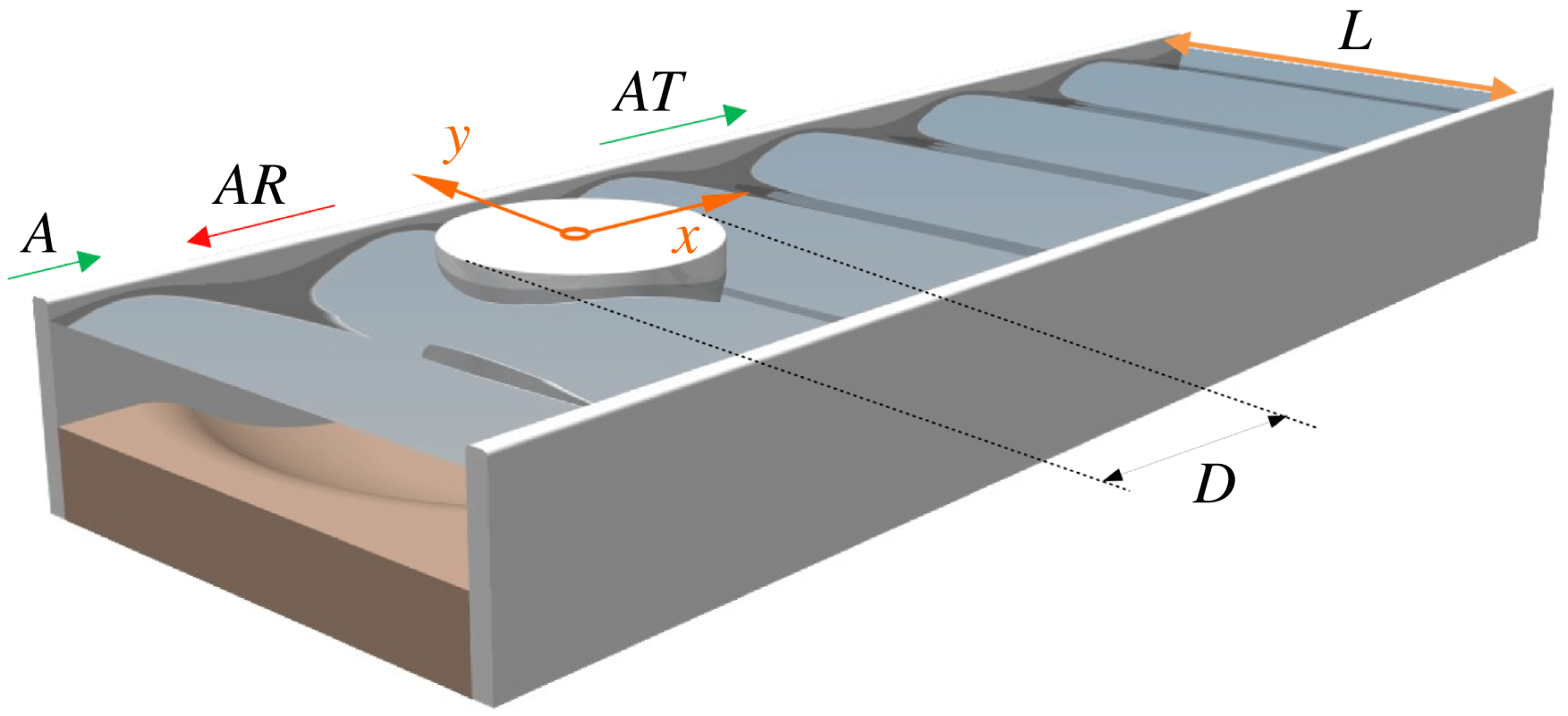
The water-wave system: a cylinder with diameter
 $D$
is shifted from the centreline of a waveguide of width
 $L$
. The incident wave, of amplitude
 $A$
is reflected and transmitted with scattering coefficients
 $(R,T)$
.

2 Modelling
2.1 Governing equations and configuration
We consider the propagation of water waves in a waveguide of width
 $L$
which contains a vertical surface-piercing cylinder of diameter
 $D$
slightly shifted from the centreline of the channel (figure 1). In the vicinity of the cylinder, we shall consider a varying bathymetry
 $z=-h(x,y)$
that is sought to reduce significantly (in a sense which will be specified in the following section) the very strong scattering due to both the background scattering and the existence of a Fano resonance.
For a smooth bathymetry
 $h(x,y)$
, the propagation of water waves can be described by a modified mild-slope equation which accounts for the dispersion and for variations of the bed (Chamberlain & Porter Reference Chamberlain and Porter1995). Defining
 $\unicode[STIX]{x1D735}=(\unicode[STIX]{x2202}_{x},\unicode[STIX]{x2202}_{y})$
, the modified mild-slope equation in the harmonic regime (convention
 $\text{e}^{-\text{i}\unicode[STIX]{x1D714}t}$
, where
 $\unicode[STIX]{x1D714}$
is the frequency) reads as
 $$\begin{eqnarray}\displaystyle \unicode[STIX]{x1D735}(c_{p}c_{g}\unicode[STIX]{x1D735}\unicode[STIX]{x1D702})+k^{2}c_{p}c_{g}\unicode[STIX]{x1D702}+g[u_{1}(h)\unicode[STIX]{x1D6FB}^{2}h+u_{2}(h)(\unicode[STIX]{x1D735}h)^{2}]\unicode[STIX]{x1D702}=0, & & \displaystyle\end{eqnarray}$$
where
 $\unicode[STIX]{x1D702}(x,y)$
is the free-surface elevation and with
 $$\begin{eqnarray}\displaystyle \left.\begin{array}{@{}rcl@{}}u_{1}(h)\ & =\ & \displaystyle \frac{\operatorname{sech}^{2}(kh)}{4(K+\sinh (K))}[\sinh (K)-K\cosh (K)],\\ u_{2}(h)\ & =\ & \displaystyle \frac{k\operatorname{sech}^{2}(kh)}{12[K+\sinh (K)]^{3}}\{\!K^{4}+4K^{3}\sinh (K)-9\sinh (K)\sinh (2K)\\ \ & \ & +\,3K[K+2\sinh (K)][\cosh ^{2}(K)-2\cosh (K)+3]\!\}.\end{array}\right\} & & \displaystyle\end{eqnarray}$$
In the above relations,
 $g$
is the gravity constant,
 $k$
is the wavenumber given by the linear dispersion relation at the local depth
 $h$
:
 $$\begin{eqnarray}\displaystyle \unicode[STIX]{x1D714}^{2}=gk\tanh kh, & & \displaystyle\end{eqnarray}$$
 $K=2kh$
, and
 $c_{p}=\unicode[STIX]{x1D714}/k$
and
 $c_{g}=\text{d}\unicode[STIX]{x1D714}/\text{d}k$
are the phase and the group velocities, respectively. Next, Neumann boundary conditions
 $$\begin{eqnarray}\displaystyle \unicode[STIX]{x2202}_{n}\unicode[STIX]{x1D702}=0, & & \displaystyle\end{eqnarray}$$
apply at the rigid boundaries of surface-piercing vertical obstacles, which, in our case, are the walls of the channel, at
 $y=\pm L/2$
, and the circular cylinder, at
 $x^{2}+(y-y_{0})^{2}=D^{2}/4$
, where
 $y_{0}$
represents the shift of the cylinder from the centreline. We shall consider a frequency range such that
 $kL<\unicode[STIX]{x03C0}$
, where only the plane mode is propagating in the waveguide.
Far from the cylinder and its cloaking region, the water depth is constant at
 $h=h_{0}$
, and (2.1) simplifies to the Helmholtz equation
 $$\begin{eqnarray}\displaystyle \unicode[STIX]{x0394}\unicode[STIX]{x1D702}+k^{2}\unicode[STIX]{x1D702}=0, & & \displaystyle\end{eqnarray}$$
thus, as only the plane mode is propagating,
 $\unicode[STIX]{x1D702}$
can be written in the far field as
 $$\begin{eqnarray}\displaystyle \unicode[STIX]{x1D702}(x,y)=\left\{\begin{array}{@{}ll@{}}A(\text{e}^{\text{i}kx}+R\text{e}^{-\text{i}kx}),\quad & \text{in the region I},\\ AT\text{e}^{\text{i}kx},\quad & \text{in the region II},\end{array}\right. & & \displaystyle\end{eqnarray}$$
where
 $A$
is the amplitude of the incident wave and
 $R$
(respectively
 $T$
) is the reflection (respectively transmission) coefficient. The regions I and II correspond to far-field regions at
 $x<0$
and
 $x>0$
, respectively, where the evanescent field excited in the vicinity of the cylinder can be neglected. We shall now specify how the cloaking effect is estimated and how the bathymetry
 $h(x,y)$
is constructed in order to realize such a cloaking.
2.2 Optimization problem
Cloaking often refers to the cancellation of the scattering coefficients at a single frequency (see, for example, Porter & Newman Reference Porter and Newman2014). As already mentioned, a Fano resonance takes place in our system which produces a strong scattering in addition to a background scattering out of the resonance. Thus, in order to obtain a broadband cloaking of the cylinder, instead of looking for the cancellation of the scattering at a single frequency, we choose to minimize the reflection coefficient in the whole frequency range
 $k\in (k_{1},k_{2})$
, with
 $k$
the wavenumber at the depth
 $h_{0}$
. We have chosen
 $k_{1}=0.16\unicode[STIX]{x03C0}/L$
and
 $k_{2}=\unicode[STIX]{x03C0}/L$
in the following. Note that this minimization can yield cancellation of backscattering and thus total transmission, but does not provide invisibility of the scatterer due to a potential phase shift in transmission.
Our problem is set as an optimization problem, and we define an objective function
 $\unicode[STIX]{x1D6F9}$
which minimizes the backscattered energy; it is defined as
 $$\begin{eqnarray}\displaystyle \unicode[STIX]{x1D6F9}=\displaystyle \frac{\displaystyle \int _{k_{1}}^{k_{2}}|R|^{2}\,\text{d}k}{\displaystyle \int _{k_{1}}^{k_{2}}|R_{ref}|^{2}\,\text{d}k}, & & \displaystyle\end{eqnarray}$$
where
 $R_{ref}$
denotes the reflection coefficient for the reference case of a flat bathymetry
 $h(x,y)=h_{0}$
, whereas
 $R$
corresponds to the reflection coefficient for a variable bathymetry. Following the same reasoning as Porter & Newman (Reference Porter and Newman2014) and keeping a minimal number of degrees of freedom, we restrict ourselves to bathymetries described, in polar coordinates
 $(r,\unicode[STIX]{x1D703})$
with an origin at the centre of the cylinder, in the following way:
 $$\begin{eqnarray}\displaystyle \left.\begin{array}{@{}c@{}}h(r,\unicode[STIX]{x1D703})=h_{0}g(r,\unicode[STIX]{x1D703}),\quad r\leqslant b,\\ g(r,\unicode[STIX]{x1D703})=1+(A_{0}+A_{1}\cos 2\unicode[STIX]{x1D703})f(r),\end{array}\right\} & & \displaystyle\end{eqnarray}$$
where
 $$\begin{eqnarray}\displaystyle f(r)=2\left(\frac{b-r}{b-D/2}\right)^{2}, & & \displaystyle\end{eqnarray}$$
and with the three degrees of freedom
 $A_{0}$
,
 $A_{1}$
,
 $b$
that will be optimized. The parameter
 $b$
is the extent of the cloaking region in the
 $x$
-direction (
 $b$
can be larger than
 $L$
). By construction, the bathymetry defined in (2.8) has the following properties:
 $$\begin{eqnarray}\displaystyle h|_{r=b}=h_{0},\quad \left.\frac{\unicode[STIX]{x2202}h}{\unicode[STIX]{x2202}r}\right|_{r=b}=0, & & \displaystyle\end{eqnarray}$$
which ensures a smooth variation at the boundaries of the cloaking region. In addition, we shall account for three constraints. The first one is that we impose a finite extent of the cloaking region, typically
 $$\begin{eqnarray}\displaystyle b<10L. & & \displaystyle\end{eqnarray}$$
Next, we impose a bathymetry with no surface-piercing area, i.e.
 $$\begin{eqnarray}\displaystyle g(r,\unicode[STIX]{x1D703})>0, & & \displaystyle\end{eqnarray}$$
(such area would produce the failure of the mild-slope equation). Eventually, we impose
 $$\begin{eqnarray}\displaystyle \max _{(r,\unicode[STIX]{x1D703})}|\unicode[STIX]{x1D735}h|<1, & & \displaystyle\end{eqnarray}$$
which guaranties the validity of the mild-slope equation. These conditions define a region bounded in the parametric space
 $(A_{0},A_{1},b)$
; afterwards the global minimum of
 $\unicode[STIX]{x1D6F9}$
can be determined straightforwardly (see Appendix).
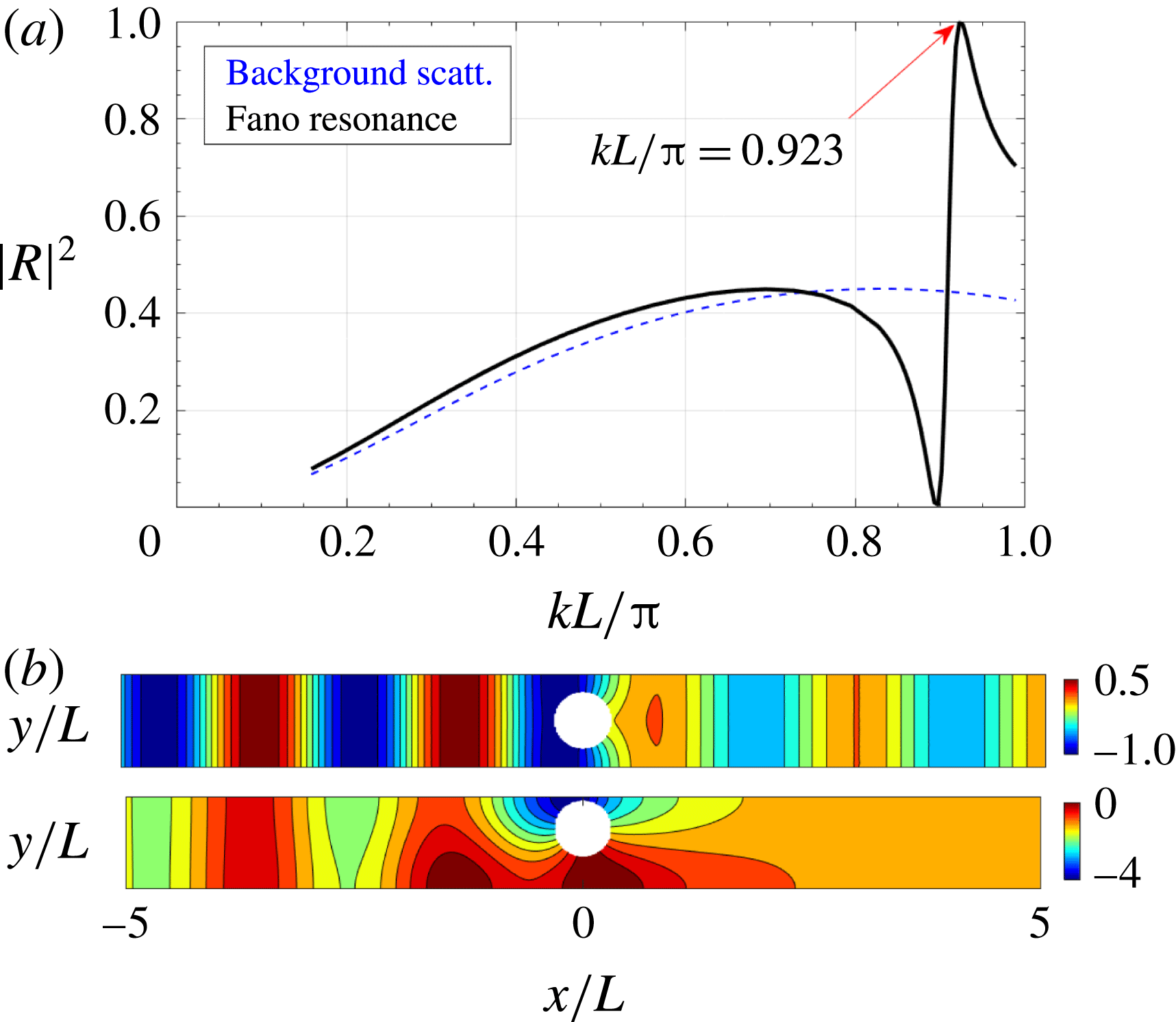
The Fano resonance for a flat bathymetry. (a) Reflection coefficient
 $|R|^{2}$
as a function of frequency
 $kL/\unicode[STIX]{x03C0}$
for the off-centreline cylinder (black solid line); the case of a on-centreline cylinder corresponding to background scattering is shown for comparison (blue dashed line). (b) Real part of the field at
 $kL/\unicode[STIX]{x03C0}=0.923$
for the on-centreline (top) and the resonating off-centreline (bottom) configurations.

3 Numerical results
Numerical calculations are performed for a configuration with a water depth
 $h_{0}=0.07L$
. The cylinder has a diameter
 $D=0.6L$
and is shifted from the centreline by a distance
 $0.15L$
. We solve the problem (2.1) using the finite-element method package of MATLAB in a domain
 $x\in (-10,10)L$
. With a mesh element of size smaller than
 $\unicode[STIX]{x1D706}_{min}/40$
, where
 $\unicode[STIX]{x1D706}_{min}$
is the smallest wavelength at
 $kL=\unicode[STIX]{x03C0}$
, the energy flux is conserved with less than 0.3 % error.
3.1 The reference case with a flat bathymetry
We first address the scattering of the cylinder within a waveguide with flat bathymetry
 $h(x,y)=h_{0}$
. The Fano resonance is observed in figure 2(a), where we report
 $|R|^{2}$
against
 $kL/\unicode[STIX]{x03C0}$
(solid black line). Also visible is the increase in the scattering strength when compared to the background scattering that corresponds to the symmetric case (the cylinder is on the centreline, blue dashed line). For the off-centreline cylinder, the reflection coefficient has a striking behaviour near the resonance, with a typical Fano resonance shape (from
 $|R|=0$
for
 $kL/\unicode[STIX]{x03C0}\simeq 0.9$
to
 $|R|=1$
for
 $kL/\unicode[STIX]{x03C0}\simeq 0.92$
), while the overall curve is underlined by the smooth curve of the background scattering. The fields at the resonance are reported in figure 2(b). As expected, the scattering strength of the off-line cylinder is significant when compared to that of the on-centreline cylinder.
3.2 The cloaking case with an optimized bathymetry
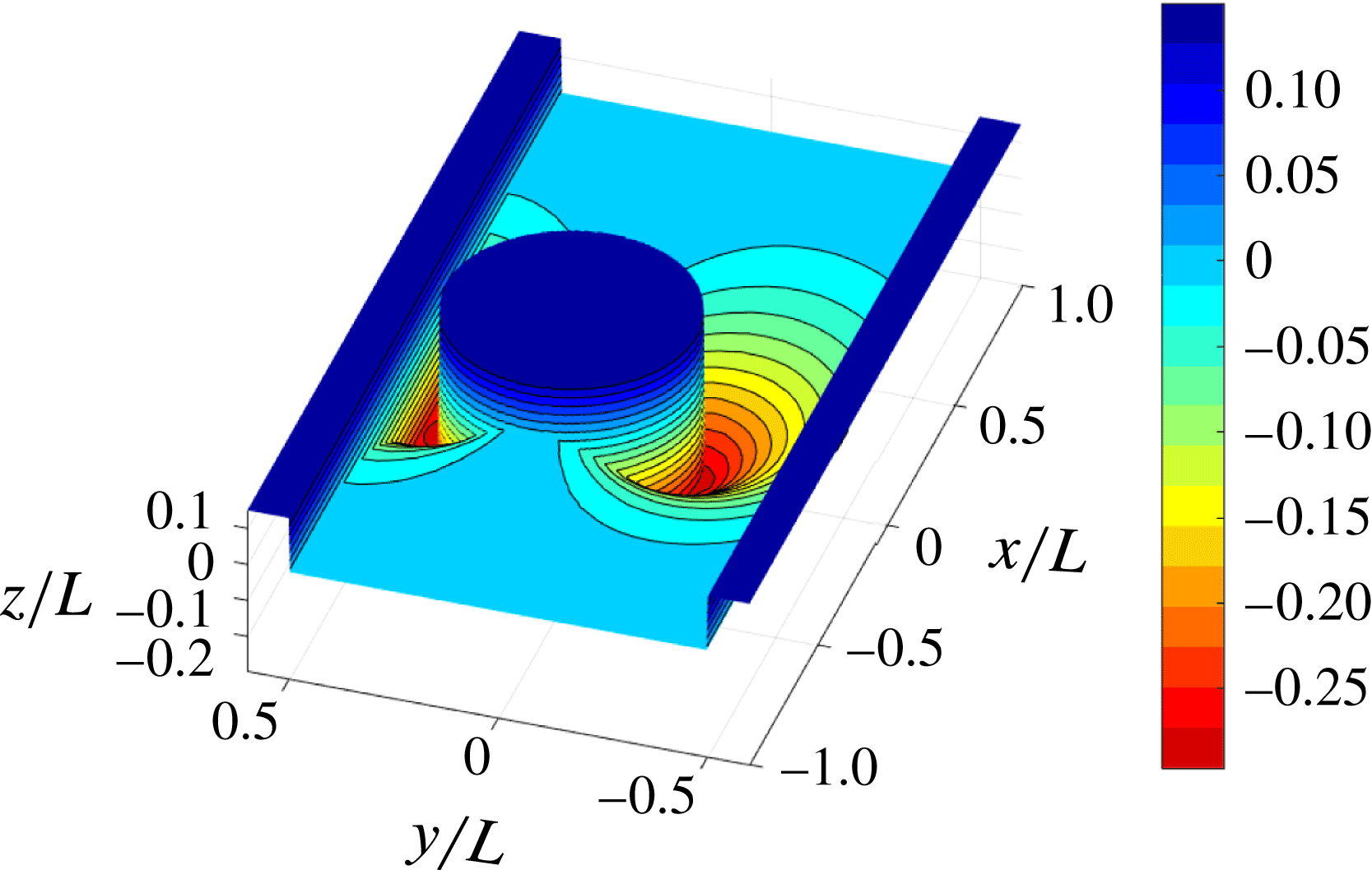
As a result of the optimization process, we obtain the bathymetry presented in figure 3. In contrast to geometrical optics expectations, when one considers the top view with right-going waves (as in figure 2 b), cloaking a cylinder within a waveguide requires deep regions in the upper and bottom neighbourhoods of the obstacle.
Cloaking bathymetry around the cylinder within a waveguide (mean depth is given as
 $z/L=0$
, whereas the mean free surface is at
 $z/L=0.07$
; the colour bar presents
 $z/L$
values).

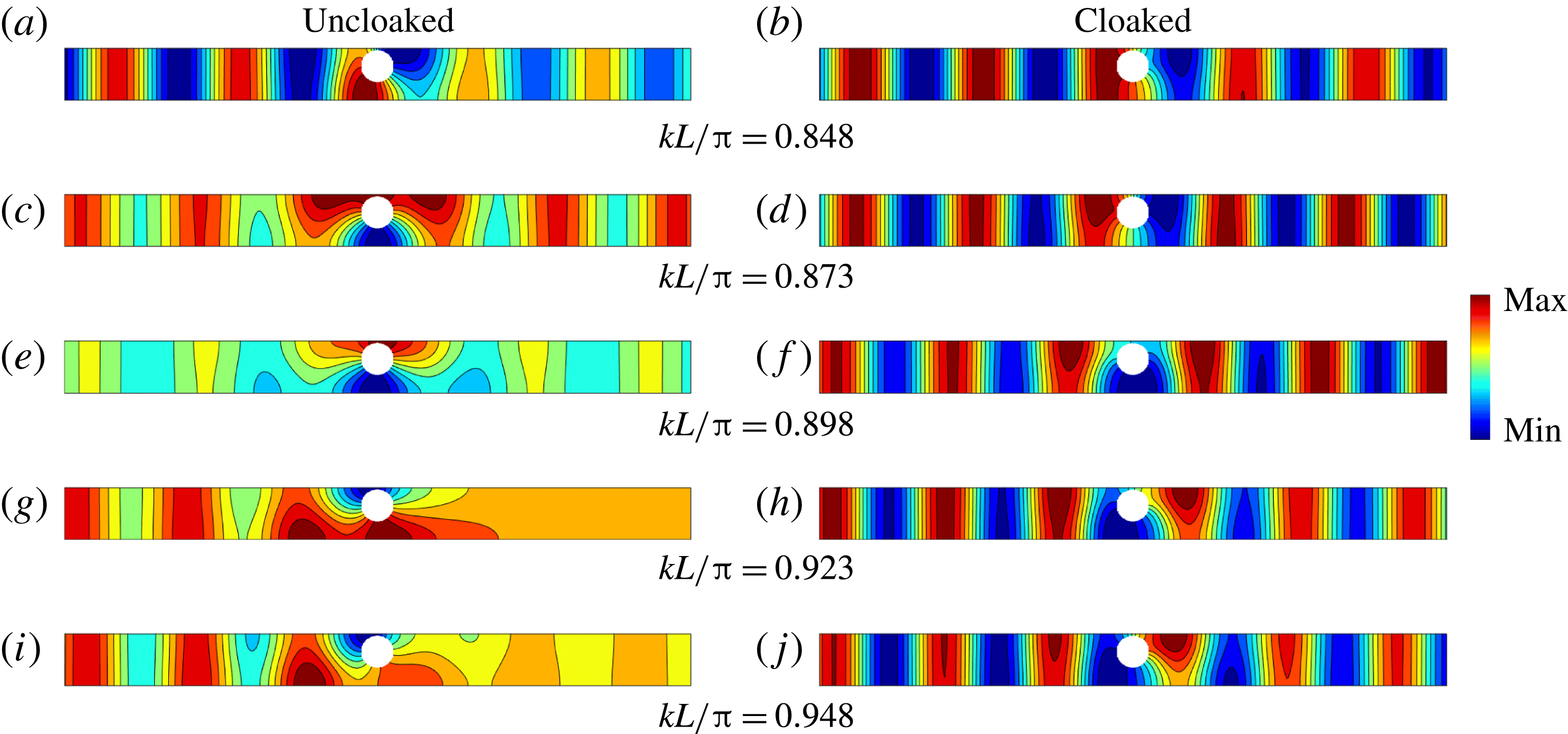
The resulting broadband cloaking effect is illustrated in figure 4. We report the real part of the fields in the reference, uncloaked, case and in the cloaked case (left and right columns, respectively) calculated numerically. For the uncloaked case with a flat bathymetry, we observe: (i) outside the resonance, a background scattering with relatively large reflection coefficients (up to
 $|R|^{2}=0.45$
); (ii) close to the resonance, a significant increase in the wave amplitude near the cylinder with strong variations of the reflection coefficient, up to
 $|R|=1$
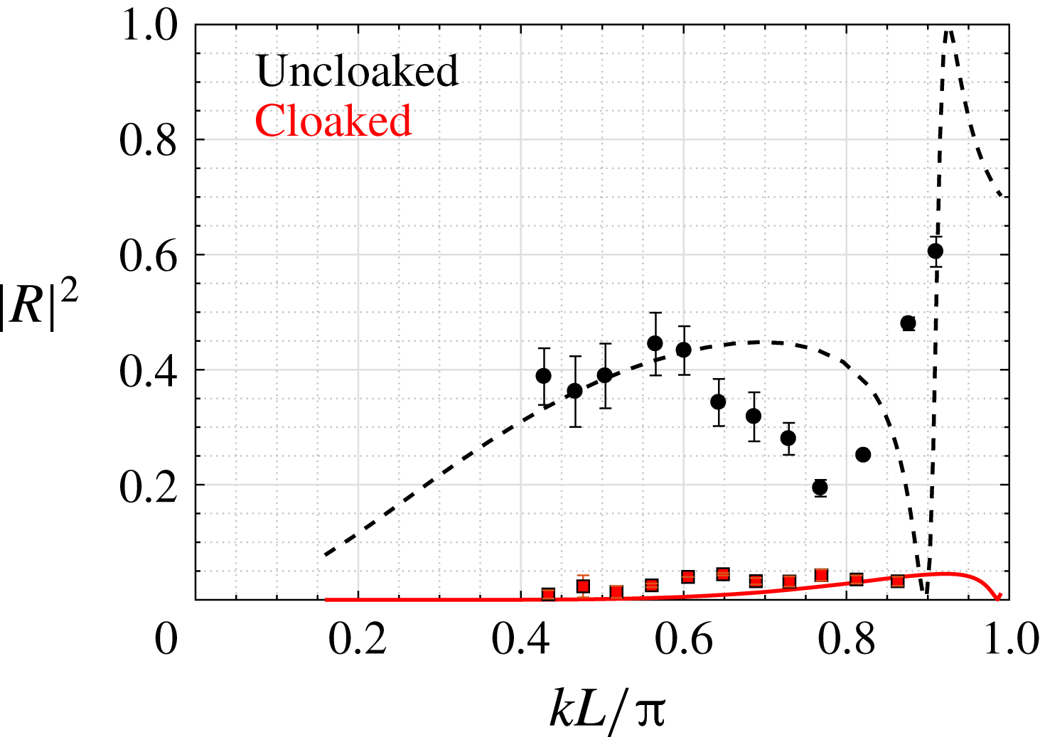
. In contrast, for the cloaked case with the optimized variable bathymetry, the scattering has been considerably reduced over the whole frequency range, with
 $|R|^{2}<0.05$
. This is confirmed quantitatively in figure 5, where we report
 $|R|^{2}$
calculated numerically in the uncloaked and cloaked cases (black dashed line and red solid line, respectively).
Numerical results. Broadband cloaking of background scattering and Fano resonance: real part of the fields
 $\unicode[STIX]{x1D702}(x,y)$
corresponding to a geometry with the flat, uncloaked, bathymetry (a,c,e,g,i) and with the cloaking zone (b,d,f,h,j). The max (min) value is typically of the order of 1 (
 $-$
1).

4 Experimental realization of the cloaked cylinder
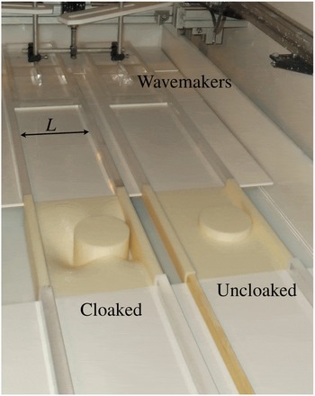
The experimental set-up is presented in figure 6. Two waveguides with flat and varying bathymetries have been manufactured using a 3D printer Fortus 250mc. Each waveguide has a length 160 cm and a width
 $L=14.3$
cm. With
 $D=0.6L=8.58$
cm,
 $h_{0}=0.07L=1$
cm, the experimental conditions are the same as in the numerics in the previous section. The waves are generated using a wavemaker connected to a linear motor, resulting in vertically oscillating horizontal plates of the same width as the waveguide; the typical wave amplitude is
 $A\sim 1.5$
mm. Eventually, spurious reflections at the end of the tank are avoided using a beach in the form of slightly inclined plate.
Cloaking of the cylinder, numerical (lines) and experimental (symbols) results:
 $|R|^{2}$
as a function of
 $kL/\unicode[STIX]{x03C0}$
for the uncloaked and for cloaked cases (black dashed line and red solid line, respectively). Black circles and red squares represent the corresponding experimental results. Error bars represent the standard deviation of multiple measurements.

The surface elevation fields are characterized using an optical method termed Fourier transform profilometry (FTP) (Cobelli et al.
Reference Cobelli, Maurel, Pagneux and Petitjeans2009a
; Maurel et al.
Reference Maurel, Cobelli, Pagneux and Petitjeans2009; Przadka et al.
Reference Przadka, Cabane, Pagneux, Maurel and Petitjeans2012). Sinusoidal fringes are projected by a digital projector over an area of
 $75\times 42~\text{cm}^{2}$
covering the two waveguides. With
 $1920\times 1080~\text{pixel}^{2}$
in the projection area, the spatial resolution is 0.39 mm in both directions. Next, we extract the harmonic component of the surface elevation field in the following way:
 $$\begin{eqnarray}\displaystyle \hat{\unicode[STIX]{x1D702}}_{\unicode[STIX]{x1D714}}(x,y)=\frac{2}{T}\int _{0}^{T}\unicode[STIX]{x1D702}(x,y,t)\text{e}^{\text{i}\unicode[STIX]{x1D714}t}\text{d}t, & & \displaystyle\end{eqnarray}$$
where
 $\unicode[STIX]{x1D714}$
is the fundamental frequency and
 $T=2\unicode[STIX]{x03C0}/\unicode[STIX]{x1D714}$
. Typical examples of the measured fields
 $\text{Re}(\hat{\unicode[STIX]{x1D702}}_{\unicode[STIX]{x1D714}})$
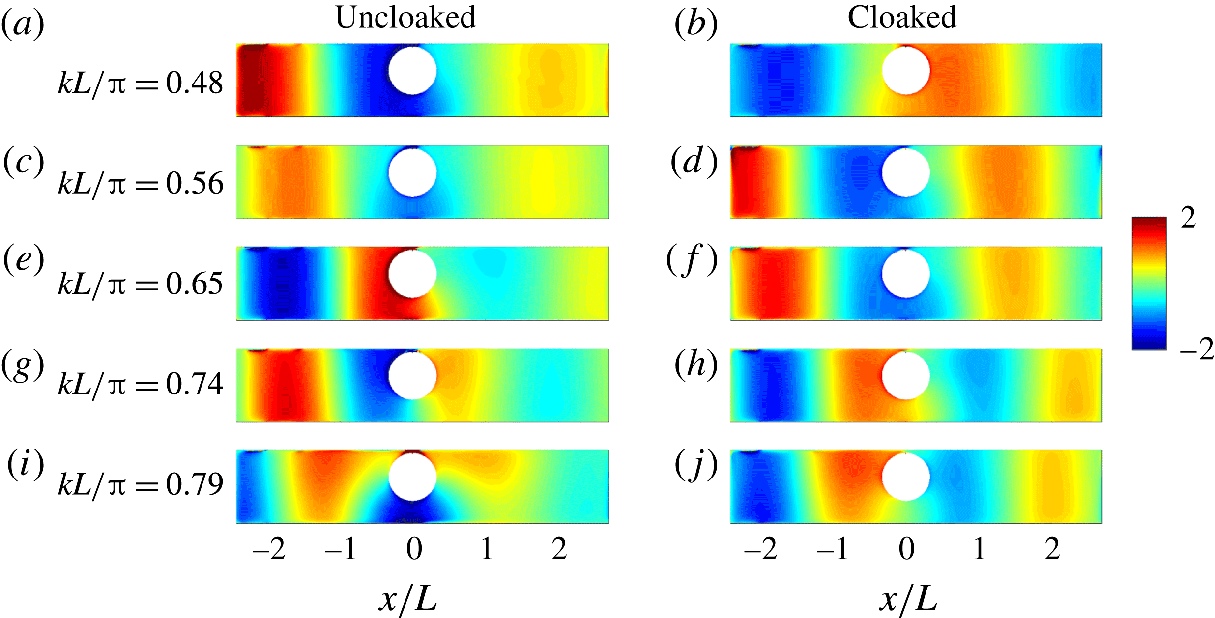
are presented in figure 7 for
 $kL/\unicode[STIX]{x03C0}\in (0.5,0.8)$
. In the uncloaked case, low transmission is observed and the cloaking is visible, with a significant increase in the transmission.
Experimental set-up: the cylinder with the cloaking region (left channel) and the cylinder with a flat bathymetry (right channel). The width of the channels is
 $L=14.3$
cm and the water depth is
 $h_{0}=1$
cm.

To go further, we extract the scattering coefficients by making use of our experimental determination of the complex fields
 $\hat{\unicode[STIX]{x1D702}}_{\unicode[STIX]{x1D714}}$
. These fields are projected onto the transverse functions
 $g_{n}(y)=A_{n}\cos (n\unicode[STIX]{x03C0}y/L)$
, with
 $A_{0}=1/\sqrt{L}$
and
 $A_{n>0}=\sqrt{2/L}$
yielding, for
 $n\geqslant 0$
,
 $$\begin{eqnarray}\displaystyle \unicode[STIX]{x1D702}_{n}(x)=\int _{0}^{L}\hat{\unicode[STIX]{x1D702}}_{\unicode[STIX]{x1D714}}(x,y)g_{n}(y)\,\text{d}y. & & \displaystyle\end{eqnarray}$$
Next, we identify the obtained plane mode component
 $\unicode[STIX]{x1D702}_{0}(x)$
to its expected form in the far field, equation (2.6), to get the scattering coefficient
 $R$
and
 $T$
(in practice, we also account for the reflection from the beach). The results for the reflection coefficient are shown in figure 5 (black circles and red squares), in good agreement with the numerical results. In the uncloaked case, there is a qualitative agreement; the discrepancies can be explained by the fact that the theory does not include viscous damping, which has an important contribution near the sharp Fano resonance (the measured absorption goes to 60 % near the resonance frequency). In the cloaked case, the measured
 $|R|^{2}$
is found to be smaller than 0.06 in the entire range of frequencies, which confirms the efficiency of the cloaking region. It is worth noting that the nonlinear effects and the capillary effects, which are present near the surface-piercing regions, do not affect the cloaking efficiency.
Experimental measurements: the normalized real part of the complex fields
 $Re(\hat{\unicode[STIX]{x1D702}}_{1})/|A|$
(where
 $A$
denotes the amplitude of the incident wave) obtained experimentally for the reference (a,c,e,g,i) and the cloaked geometries (b,d,f,h,j). Incident waves from the left.

5 Conclusions
In this paper we considered the scattering of water waves by a surface-piercing vertical cylinder in a waveguide with finite depth. Breaking the symmetry of the system, by shifting the cylinder from the centreline, results in a Fano resonance producing strong scattering, reaching total reflection near the resonance frequency. We showed that using a relatively simple bathymetry (with three degrees of freedom in the optimization process) one can avoid resonance and reduce both the resonant scattering and the background scattering by almost two orders of magnitude in a broad frequency range. Numerical results were confirmed experimentally with quantitative agreement.
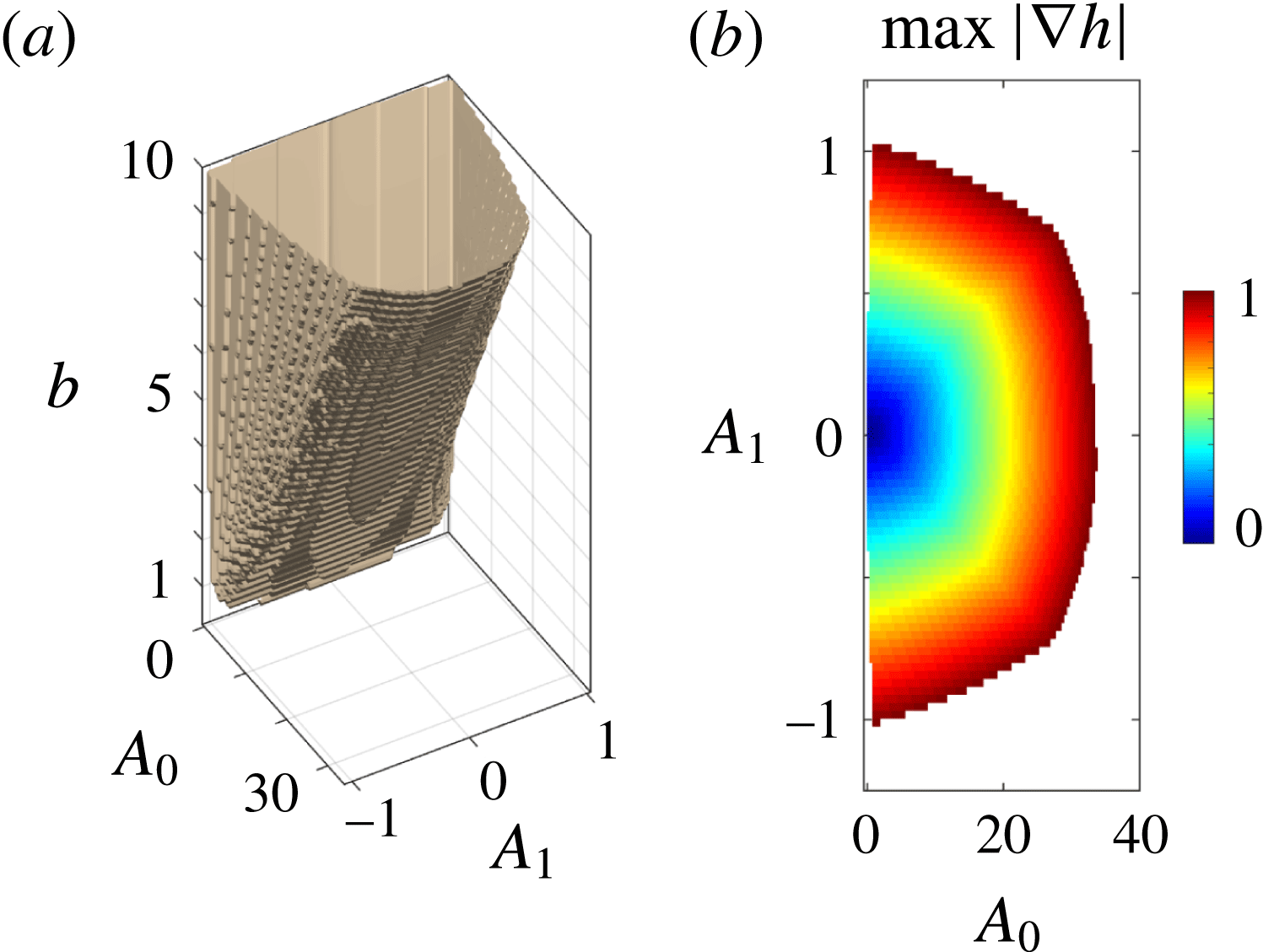
(a) The bounded region in the parametric space
 $(A_{0},A_{1},b)$
resulting from the constraints. (b) Example of bounded region for
 $(A_{0},A_{1})$
(here for
 $b=8L$
) imposed by the constraint
 $|\unicode[STIX]{x1D735}h|<1$
.

Acknowledgement
A.M., V.P. and P.P. acknowledge support from the Agence Nationale de la Recherche through the grant DYNAMONDE ANR-12-BS09-0027-01.
Appendix. Optimization process
In this section we present results concerning the optimization process. The optimization problem is set on
 $\unicode[STIX]{x1D6F9}$
, equation (2.7). With
 $R$
calculated for waves propagating over a varying bathymetry of the form (2.8),
 $\unicode[STIX]{x1D6F9}$
is minimized with the constraints (i)
 $b<10L$
, (ii)
 $g(r,\unicode[STIX]{x1D703})>0$
and (iii)
 $\max _{(r,\unicode[STIX]{x1D703})}|\unicode[STIX]{x1D735}h|<1$
. These constraints narrow the available parametric space (
 $A_{0},A_{1},b$
), resulting in a bounded region as illustrated in figure 8(a). Note that, for a given
 $b$
, it is the constraint (iii) which ensures that
 $(A_{0},A_{1})$
are bounded; see figure 8(b) where we present
 $\max |\unicode[STIX]{x1D735}h|$
as a function of
 $A_{0}$
and
 $A_{1}$
for
 $b=8$
. Hence, the optimization is simply done by minimizing
 $\unicode[STIX]{x1D6F9}$
in this bounded region.