I. INTRODUCTION
The development of wireless technology in recent years has catapulted the demand for handheld devices for communication. The requirement is to cover more than one frequency band to support many wireless applications in commercial area. An ideal possibility is to integrate multiple bands in a single antenna device that can handle several usable frequency bands of various applications. As a matter of fact, the antenna design for handheld devices must be miniaturized in terms of space and design complexity for the fabrication of antenna to be cost effective.
Micro strip printable antenna has been more attracted for it satisfies the basic requirements of an antenna design such as low profile, simple to manufacture, and low cost [Reference Elsadek1]. Recently many good performance multiband and wideband antennas are reported for several applications including global system for mobile communication (GSM), global positioning system (GPS), digital cellular radio systems (DCRS), personnel communications service (PCS), wireless local area network (WLAN) and worldwide interoperability for microwave access (WiMAX). Several techniques have been employed to achieve multiband and miniaturized antennas like multi-layer stacked patches, slot loading techniques, shorting pins and posts, planar patch antennas, etc. Multiband antenna design using stacked patches providing wide bandwidth with good return loss and performance is acceptable in mobile environment [Reference Faisal, Quboa and Ali2]. But the multi-layer patch antenna complicates the fabrication as well as height of the patch antenna gets increased, which will generate surface wave. Various types of slot loading multi-band antennas were reported. In [Reference Ni, Jiao, Weng and Zhang3], Tao Ni et al. states that multiple operating bands, stable antenna gain, and almost an omni-directional radiation pattern can be achieved by loading T-shaped slots in the terminals of a T-shaped antenna with good impedance matching. Antenna performance is independent of feed methods. In [Reference Ansari, Verma and Singh4] C-shape slot loaded in disk shape patch to achieve quad band features for the applications of S-, C-, and X-bands is designed. However, frequency tuning is not attained in it. A miniaturized quad band antenna using slots with modified ground structure is reported in [Reference Das5] in which bandwidth enhancement has been achieved. In [Reference Liu, Ghavami and Chung6], dual and tri operating frequency bands is achieved by using meandered strip and protruding stubs. Also various shaped planar patch antenna like H shape and U shape, has been used as tuning element for achieving multiband was reported [Reference Sheta, Mohra and Mahmoud7–Reference Sun, Chun, Zeng and Yang8].
The multiple input multiple output (MIMO) technology offers high data rate, large coverage, and spectral efficiency with multiple antennas at transmitter and receiver side. The important features to be taken care of while designing MIMO antenna systems are isolation, mutual coupling, and correlation [Reference Blanch, Romeu and Corbella9]. Several printed antennas for MIMO applications have been proposed over the years [Reference Kharche, Reddy and Mukherjee10–Reference Ali Nezhad and Hassani12]. MIMO antenna has been designed for the applications of Bluetooth, Wi-Fi, WiMAX, and UWB using two orthogonally separated semi-circular monopole antennas [Reference Blanch, Romeu and Corbella9]. The MIMO antenna for WLAN and WiMAX applications have been proposed with four slot antenna elements in which quad frequency bands with correlation of <0.05 was achieved [Reference Kharche, Reddy and Mukherjee10]. In [Reference Karimian, Oraizi, Fakhte and Farahani11] an E-shaped monopole antenna is proposed for MIMO systems to cover tri bands of 2.4, 5.4, and 5.8 GHz.
In this paper, a modified T slot on a circular patch compact quad band antenna for MIMO applications is proposed. Work on this paper is towards the achievement of a compact size multi band microstrip antenna with simple structure and also cost effective. The results of slot loading technique in patch antennas provide multiple bands and also the size gets reduced. Likewise, the proposed design of T-slot on patch provides four frequency bands of 2 GHz (2–2.2 GHz), 4.8 GHz (4.6–4.9 GHz), 5.4 GHz (5.28–5.44 GHz), and 6.6 GHZ (6.15–6.5 GHz) covering the applications of S-band (2–4 GHz), C-band (4–8 GHz), and LTE and compact size antenna. Also the proposed design is arranged in two elements configuration for MIMO applications, which has good response in envelope correlation coefficient (ECC) and diversity gain. However slot loading is not a new technique, the proposed design has the following advantages over papers reported in [Reference Elsadek1–Reference Karimian, Oraizi, Fakhte and Farahani11].
-
• Simple structure of loading T slot on the circular patch
-
• Miniaturized size of antenna
-
• Independent tuning of frequency bands
-
• Simple to fabricate and cost effective
-
• Low correlation <0.1 and reduced mutual coupling.
Section II of this paper describes the antenna geometry and design. In Section III, the details of simulation, measured results of single element and performance parameters of the antenna are provided. Section IV covers the two element MIMO antenna design and its performance.
II. ANTENNA GEOMETRY AND DESIGN
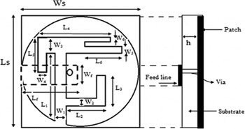
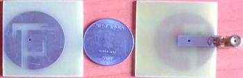
Figure 1 shows the configuration of the proposed compact quad band modified T-slot in a circular patch antenna, which is fed by 50 Ω micro strip feed line. The design uses the substrate as low cost FR4 epoxy with a relative permittivity of ε r = 4.4 at a height of 1.5748 mm. The proposed antenna is designed for the frequency of 2.45 GHz, which has a conventional circular patch of radius of 15.4 mm. The inclusion of modified T-slot with various wavelengths in the conventional circular patch causes a quad band performance. The total size of the miniaturized proposed antenna is 30 × 30 mm2. In Fig. 2, the photograph of the proposed T-slot antenna is shown.
Proposed compact modified T slot quad band antenna with dimensions L s = 40 mm, L f = 18 mm, L 1 = 22 mm, L 2 = 10 mm, L 3 = 6.5 mm, L 4 = 13 mm, L 5 = 8 mm, L 6 = 9 mm, W s = 40 mm, W f = 5.4 mm, W 1 = 3 mm, W 2 = 2 mm, W 3 = 3.5 mm, W 4 = 2 mm, W 5 = 1.5 mm, and W 6 = 1 mm.

Photography of proposed fabricated ‘T’ slot quad band antenna.

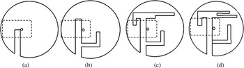
The step by step process of compact modified T-slot antenna to achieve the quad band performance is shown in Fig. 3. The design starts with a conventional circular patch antenna for the operating frequency of 2.45 GHz [Reference Balanis13]. A modified T-slot is loaded in circular patch on one side of the substrate. A feeder line of dimension L
f
X Wf
is provided on the other side of the substrate. The shorting pin of radius 0.7 mm is linked between feeder line and the radiating circular patch. The shorting pin between feeder line and the patch through substrate acts as a ground for the proposed design. A modified T-slot is achieved by introducing various wavelength slots on the patch in order to obtain quad band operation. Introduction of quarter wavelength slot, λ
g
/4 ~22 mm, where
 ${\lambda _g} = {c / {f\sqrt {{\varepsilon _{eff}}}}} $
is the guided wavelength at the operating frequency band of 5.4 GHz as shown in Fig. 3(a). The resonant frequency (f
r1) and slot parameters can be related as shown in equations (1) and (2)
 $${f_{r1}} = \displaystyle{c \over {4{l_e}\sqrt {{\varepsilon _{eff}}}}}, $$
 $${l_e} = \displaystyle{{{L_1}} \over {{W_1}}} - (2l + 0.4) + \displaystyle{{4l} \over {\sqrt {{\varepsilon _{eff}}}}}, $$
where l e is the effective length of the slot, ε eff is the effective dielectric constant, l is the correction coefficient and is predicted as 1.4535. Introducing another one-eighth of a wavelength L-slot (λ g /8 ~10 mm) with the existing one as shown in Fig. 3(b), provides a center frequency of 2 GHz. In this case the resonant frequency (f r2) and slot parameters can be related as shown in equations (3) and (4).
 $${f_{r2}} = \displaystyle{c \over {8{l_e}\sqrt {{\varepsilon _{eff}}}}}, $$
 $${l_e} = \displaystyle{{{L_2}} \over {{L_3}}} + {W_2} + \displaystyle{{8l} \over {\sqrt {{\varepsilon _{eff}}}}}. $$
By introducing half wavelength (λ g /2 ~13 mm) slot in addition to existing slots at upper part as shown in Fig. 3(c), offered the additional frequency response at 4.8 GHz. In this case the resonant frequency (f r3) and slot parameters can be related as shown in equations (5) and (6).
 $${f_{r3}} = \displaystyle{c \over {2{l_e}\sqrt {{\varepsilon _{eff}}}}}, $$
 $${l_e} = {L_4} + {L_5} - ({W_4} + {W_3} + {W_6}) + \displaystyle{{2l} \over {\sqrt {{\varepsilon _{eff}}}}}. $$
Finally, introducing another one-half wavelength (λ g /2~18 mm) slot as shown in Fig. 3(d) by slightly modifying the previous case give the frequency response at 6.2 GHz. In this case the resonant frequency (f r4 ) and slot parameters can be related as shown in equations (7) and (8).
 $${f_{r4}} = \displaystyle{c \over {4{l_e}{{\sqrt \varepsilon} _{eff}}}},$$
 $${l_e} = \displaystyle{{{L_6}} \over {{W_5}}} - 2l + \displaystyle{{4l} \over {\sqrt {{\varepsilon _{eff}}}}}. $$
Based on the appropriate slot dimensions, Quad band frequency of interest can be achieved. Thus the combined modified T-slot offers four bands at the frequencies of 2, 4.8, 5.4, and 6.2 GHz. In order to get the desired frequency bands optimized lengths of the slots are considered for designing.
Design steps of proposed quad band antenna. (a) Circular patch with single slot (Antenna 1 with resonant frequency f r1). (b) Circular patch with dual slot (Antenna 2 with resonant frequency f r2). (c) Circular patch with triple slots (Antenna 3 with resonant frequency f r3). (d) Circular patch with quad slot (Antenna 2 with resonant frequency f r4).

III. RESULTS AND DISCUSSION
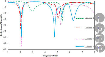
The simulated S-parameter characteristics of the proposed Modified T-slot antenna from a single band to a quad band are shown in Fig. 4. Antenna 1 has an open ended quarter wavelength slot in the circular patch and gives the response at 5.4 GHz band, which covers LTE application bands. Antenna 2, after introducing the slot of one-eighth wavelength of L-slot in addition to the previous one, provides responses at 2 and 5.4 GHz. Antenna 3, which is developed by introducing another half wavelength slot in addition to the existing slots give the responses at 2, 5.4, and 4.8 GHz. Antenna 4 in which a half wavelength slot introduced along with the previous half wavelength slot offers a band at 6.2 GHz in addition to the center frequencies of 2, 4.8, and 5.4 GHz.
Simulation S-parameter characteristics of the proposed antenna from single band to quad band.

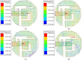
The surface current distribution of the proposed design at each frequency band of operation is shown in Fig. 5. The maximum current flow in a slot represents its corresponding resonant frequency of operation. That is to say the maximum intensity of surface current flow in L slot, which is responsible for 2 GHz band of operation. Moreover the maximum surface current flow in other slots is also responsible for its corresponding specific band of frequency.
Surface current distribution of proposed quad band antenna. (a) Surface current distribution at 2 GHz, (b) surface current distribution at 4.8 GHz, (c) surface current distribution at 5.4 GHz, and (d) surface current distribution at 6.2 GHz.

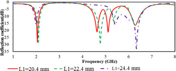
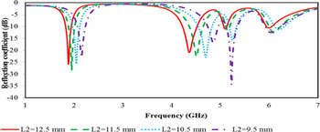
The parametric study of proposed design is done by varying the length of each slot while keeping the other slot lengths constant and also the analysis of frequency tuning is performed. By varying the length of a specific slot, the interested frequency band can be tuned accordingly. The parametric study shows that the proposed design offers an independent frequency tuning between each frequency bands. Figure 6 shows the frequency tuning of 5.4 GHz band by varying the length of the quarter wavelength slot while keeping the other slot lengths constant. When increasing the length of the slot L 1 and keeping other slot lengths constant causes the tuning of 5.4 GHz band move towards high frequency with slight tuning of 4.8 GHz band. Furthermore by decreasing the length of the one-eighth of a wavelength of the L-slot while keeping all other parameters of the design is constant, the tuned 2GHz frequency band move towards higher frequency and 4.8 GHz band move from 4.4 GHz to towards it (Fig. 7).
S 11 (dB) versus frequency in different value of L 1 provide tuning 5.4 GHz with 4.8 GHz.

S 11 (dB) versus frequency in different value of L 2 provide tuning 2 GHz with 4.8 GHz.

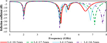
As shown in Fig. 8, by decreasing the length of the half wavelength upper slot and keeping all other bands constant the tuning of 6.6 GHz band move towards higher frequency. It is important to say that from this analysis the independent tuning of frequency bands can be achieved with the proposed design.
S 11 (dB) versus frequency in different value of L 4 provide tuning 6.2 GHz.

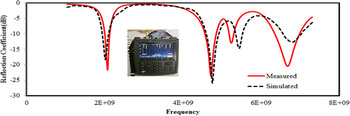
The comparison between the simulated and measured reflection co-efficient characteristics of the proposed antenna can be obtained by HFSS and Agilent's vector network analyzer is shown in Fig. 9, which shows a reasonable performance between simulated and measured results at particular bands of operation except with some amount of loss occur during fabrication and measurements.
Simulated and measured S-parameter (|S 11|) of proposed ‘T’ slot quad band antenna.

IV. TWO ELEMENT MIMO ANTENNA
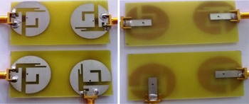
The compact modified T slot circular patch quad band antenna elements discussed in detail in Section II can be used for MIMO applications when arranged in arrays. The photograph of the fabricated two element array antenna is shown in Fig. 10. In order to achieve the polarization diversity, each element of MIMO antenna is arranged in 180°or orthogonal fashion. In these arrangements the spacing between the elements is 0.139 λ, where λ is the wavelength of the lowest resonant frequency. In general for the good MIMO antenna system, which has low correlation and high isolation and also the mutual coupling between the elements, must be low. The closeness of simulations and measurements results can decide the channel capacity of MIMO system [Reference Lu and Huang14]. In fact in MIMO antenna, the effect of sharing a common ground causes severe mutual coupling problem due to surface current. But in the proposed design the rejection of sharing the common ground plane offers low mutual coupling.
Photograph of fabricated two elements MIMO antenna, placed 90° and 180° to each other.

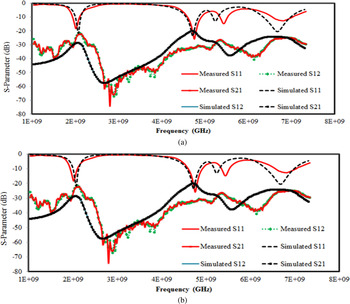
The measured and simulated S parameters of both MIMO antenna arrangements are shown in Fig. 11(a) and (b). The measured reflection coefficient S 11 of both cases shows the same result as that of individual element, which are matched with the simulation result. The mutual coupling S 12 of orthogonally placed MIMO antenna shows a reduced mutual coupling of nearly <−20 dB to −80 dB compared with 180° placed MIMO antenna, which have only <−10 dB to −50 dB. Since the orthogonally placed elements do not affect each others performance it leads to low antenna correlation and the individual elements are in compact size.
Measured and simulated S parameters of two element 90° and 180° placed MIMO antenna. (a) Comparison of measured and simulated two element orthogonally (90°) placed MIMO antenna. (b) Comparison of measured and simulated two element 180° placed MIMO antenna.

A) Diversity performance of two element MIMO antenna
The ECC is calculated through S-parameters in a uniform environment, which is given as [Reference Kildal15],
 $${\rho _{eij}} = \displaystyle{{{{\left \vert {{s_{ii}}^{\ast}{s_{ij}} + {s_{ji}}^{\ast}{s_{jj}}} \right \vert} ^2}} \over {\left( {1 - \left( {{{\left \vert {{s_{ii}}} \right \vert} ^2} + {{\left \vert {{s_{ji}}} \right \vert} ^2}} \right)} \right)\left( {1 - \left( {{{\left \vert {{s_{jj}}} \right \vert} ^2} + {{\left \vert {{s_{ij}}} \right \vert} ^2}} \right)} \right)}}.$$
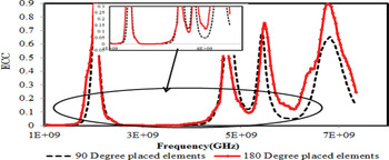
The measured ECC for two element MIMO antennas is shown in Fig. 12 by using equation (9) and measured S-parameters. In general for a typical MIMO antenna, the correlation should be <0.5. But for the proposed MIMO antenna ≤0.1 correlation can be achieved for all bands. The expanded form of graph shows the correlation for 90° and 180° placed element MIMO antenna. Both cases show a low correlation value since both cases have a reduced mutual coupling between two elements.
Measured ECC of two element MIMO antenna.

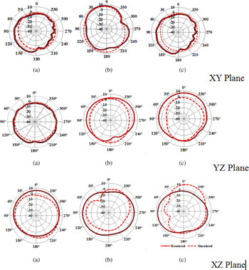
The simulated and measured radiation pattern of single antenna element in XY, YZ, and XZ plane is shown in Fig. 13. The measured radiation patterns of proposed antenna are nearly identical and mostly omnidirectional at 2 and 5.4 GHz and this may be due to similar current distribution at both operating frequencies. Due to the surface current distribution, the measured radiation pattern of proposed antenna shows a directional characteristic for 4.8 GHz.
Measured and simulated radiation pattern in three planes for the frequencies (a) 2 GHz, (b) 4.8 GHz, and (c) 5.4 GHz.

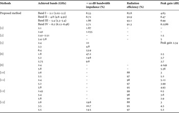
Measured gain, radiation efficiency, and impedance bandwidth for a particular operating frequency is shown in Table 1.
Measured performance of fabricated quad band antenna.

Among the measured results, the proposed method achieves 6.99 dB peak gain, which is more than that of the method presented in [Reference Faisal, Quboa and Ali2–Reference Ali Nezhad and Hassani12] and the peak radiation efficiency is 93.1%. In addition, compared with the C-shaped and L-shaped slot antenna designs in [Reference Kildal15], this proposed slot antenna design can improve the gain of frequency of interest.
V. CONCLUSION
The compact modified T-slot circular patch quad band antenna with the tuning of interested frequency band for S-band, C-band, and LTE applications is designed. The designed antenna has a compact size of 30 × 30 mm2 with the feed line. The measured results show that the attained maximum return loss is 30 dB at its one of the resonant frequency and has below 15 dB return loss for all other bands. Parametric studies show that the length of the slots provides the frequency tuning of single band of interest. The measured results of 90° and 180° placed elements, which offer a reduced mutual coupling between the elements of nearly <−20 dB to −80 dB and low correlation of ≤0.1 and the antenna provides high gain and good radiation efficiency.
ACKNOWLEDGEMENTS
The authors would like to thank Mr. Muhammed Hussain of HCL technologies, Ambattur division 5, Chennai for the support provided for radiation pattern measurements.
 Chithradevi Rajagopal received her B.E degree in Electronics and Communication Engineering and the Master of Engineering in VLSI design from Anna University, Chennai, India in 2005 and 2007, respectively. She is currently working towards Ph.D. degree at SSN College of Engineering, Chennai. Her primary research interests are Multiband MIMO antennas and EBG structures for wireless communication applications.
 Sreeja Balakrishnapillai Suseela received her Bachelor of Engineering from Bharathidasan University in 2002, Master of Engineering, and Ph.D. degrees from Sathyabhama University in the years 2004 and 2012, respectively. She has 12 years of teaching experience in various universities including Sathyabama University, India, Linton University College, Malaysia, and SSN College of Engineering, India. Her research interests include High frequency devices and structures, Smart devices, MEMS and NEMS devices and Co-integration of devices and circuits.
 Nafiza Noorullakhan received her B.E degree in Electronics and Communication Engineering and the Master of Engineering in Communication systems from Anna University, Chennai, India in 2013 and 2015, respectively. Her main research interests are design and development of smart antennas for wireless applications.
 Radha Sankararajan Professor and Head, Department of ECE, SSN College of Engineering has 24 years of teaching and 11 years of research experience in the area of Mobile Ad Hoc Networks. She has graduated from Madurai Kamaraj University, in Electronics and Communication Engineering during the year 1989. She has obtained her Master degree in Applied Electronics with First Rank from Government College of Technology, Coimbatore and Ph.D. degree from College of Engineering, Guindy, Anna University, Chennai. She has also worked as a visiting researcher at Carnegie Mellon University, USA for a period of 6 months in the area of Wireless Sensor Networks. She has 72 publications in International and National Journals and conferences in the area of Mobile Ad hoc Network and Wireless Sensor Networks. She has received IETE – S K Mitra Memorial Award in October 2006 from IETE Council of INDIA, Best paper awards in various conferences and CTS – SSN Best Faculty Award – 2007 and 2009 for the outstanding performance for the academic years 2006–07 and 2008–09.