1. MOTIVATION AND GOALS
Drawings, that is, external two-dimensional (2-D) graphical representations, are a central component of the design process (e.g., Ferguson, Reference Ferguson1992). Larkin and Simon (Reference Larkin and Simon1987) describe some of the advantages of using drawings in problem solving in general: drawings focus search, afford perceptual inferences, and enable easy recognition of elements such as shapes (e.g., circle) and spatial relations (e.g., between). According to them, these cognitive advantages accrue because drawings use location to group information about a single element, avoiding the need to match symbolic labels; drawings group all information that is used together, which helps avoid large amounts of search; and drawings automatically support perceptual inferences that are easy for humans. Ullman et al. (Reference Ullman, Wood and Craig1990) analyze the importance of drawings in engineering design.
Recognition of shapes and spatial relations in a design representation enables classification and indexing of the representations, and retrieval of appropriate design knowledge. In CAD, shape similarity among three-dimensional (3-D) design representations is a major research issue in indexing and retrieval of design and manufacturing knowledge. Cardone et al. (Reference Cardone, Gupta and Karnik2003) and Iyer et al. (Reference Iyer, Jayanti, Lou, Kalyanaraman and Ramani2005) survey the state-of-the-art in computational techniques for 3-D shape search. In contrast, we are interested in computational techniques for deeper semantic analysis of 2-D CAD drawings generated with vector-graphics tools. In particular, in addition to recognition of shapes and spatial relations in an unlabeled 2-D design drawing, we are interested in the recognition and labeling of structural components and connections depicted in the drawing. Labeling of the structural components and connections should enable deeper classification and indexing of design drawings and indexing and retrieval of the functions and behaviors of the components and connections.
This theory is implemented in a program called Archytas, which analogically infers shape and structure in a target drawing (the input) from that given in a source (or base) case. This program reads in a 2-D unlabeled drawing and, given the source drawing and associated teleological model, attempts to infer by analogy a representation of the shapes and spatial relations in the target drawing and a representation of the structural components and interconnections of the device depicted in the drawing. This method of compositional analogy works iteratively to successively higher levels of abstraction, interleaving mapping, and transfer at various levels to construct a new structural model.
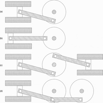
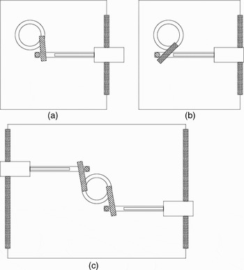
Let us consider the task of mapping the source drawing illustrated in Figure 1a to the similar target drawing illustrated in Figure 1b. If we treat the problem as one of first recognizing the geometric elements and spatial relations among them, then we can treat this representation as a labeled graph: A contains B, C is adjacent to D, and so on. A graph-theoretic method for analogy-based recognition may then be used to find a consistent mapping between the graphs representing the source and target drawings. However, the method runs into difficulty for the target drawing shown in Figure 1c or 1d with 1a as the source drawing. In this problem, the number of components, and thus the number of shapes, is different, and either the graph-theoretic method would have to relax the constraint of one-to-one mapping, or else the analogy would have to be performed twice to transfer a model successfully from Figure 1a to 1c or 1d. Figure 2 illustrates a similar example from the domain of door latches.
(a) A sample source drawing of a piston and crankshaft assembly, (b) a target drawing of the same device with the piston now at the top of its range of motion, (c) a sample target drawing of a double piston and crankshaft assembly, and (d) a sample target drawing with two crankshafts and a single piston. In all cases the task is to transfer and adapt the model of the device in the first drawing to the target.

(a) A door latch mechanism consisting of a cam that turns (e.g., from the turning of a door handle, not shown) and pulls back on a shaft, which in turn pulls back the bolt (or latch) that pulls back through the door. (b) The same door latch but with the latch pulled back. (c) A double door latch with latches on both sides of the door. Part (a) is a source drawing, and (b) and (c) are target drawings.

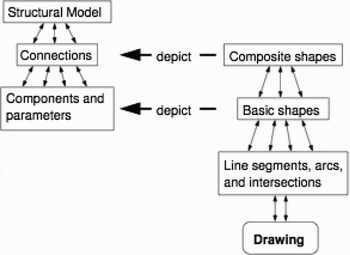
To address the above difficulties, our method of compositional analogy performs analogy at multiple levels of abstraction. The analogical mapping and transfer at these levels is enabled by organizing knowledge of the source case at multiple levels. Figure 3 illustrates the knowledge organization in a source case. The structure, shape, and drawing in a source case form an abstraction hierarchy, where structure is a specification of components and structural relations along with properties (height, width, etc.) and variable parameters (e.g., position or angle of moving components). These models are based on the structural portion of structure–behavior–function (SBF) models (Goel & Chandrasekaran, Reference Goel and Chandrasekaran1989; Goel, Reference Goel1991, Reference Goel1996).
The multilevel hierarchy of drawing, shape, and structure. Basic and composite shapes are patterns of line intersections, which depict components and structural relations, respectively.

Our method of compositional analogy first constructs a representation of individual lines and circles and intersection points in the target drawing, and then analogically infers shapes over this representation by grouping multiple symmetric mappings at the level of lines and intersections. Using these groups it infers shape patterns in the target and sets up a mapping at the level of whole shapes. This shape-level mapping then informs the transfer of structural elements from source to target, resulting in a full structural model for the depicted device in the target drawing as well as a component-level mapping of the source model onto this target model.
2. THE STRUCTURE OF SHAPES
Because the task is the analogical comparison of drawings, and drawings contain shapes that depict model elements (components etc.), these shapes must be represented in a way that facilitates this comparison. Note that the shape representation of the source drawing is given; the issue here is what must we calculate from the input drawing to facilitate analogical comparison with the source at the level of shape. When a drawing is represented symbolically for analogical comparison, symbols are typically associated with shapes. In this symbolic representation, the shape—which is a composite geometric structure, a point set in the real plane—becomes an atomic entity. If analogy involves the alignment of symbol structures, then analogical comparison between two drawings can only be successful when these symbol structures are isomorphic. However, whether two symbol structures are aligned depends on how the shapes in the symbol structures are decomposed. In particular, an intelligent agent cannot compose line segments into shapes unless it already knows what shapes are supposed to be there. To address this issue, we represent shapes in the source case at multiple levels of abstraction, and use the shape representation in the source to help resolve ambiguities in constructing a representation of shapes in the target.
2.1. Lines, arcs, circles, and intersections
The first step of the process is to match each shape in the source to the whole target drawing, searching for occurrences of that shape in the target. To do this we need a robust and canonical representation of shapes, and in particular, one that is robust in the face of the visual binding problem: line segments should match regardless of whether they are drawn in the vector graphics file as a single vector or as multiple vectors. For instance, the rectangle corresponding to the upper half of the cylinder in Figure 1a might be drawn as four perpendicular lines, or it might be six lines (if the edge touching the piston is regarded as three segments instead of one); the shape must match either way. This is achieved by using what we call the augmented line intersection graph of the drawing (Yaner & Goel, Reference Yaner and Goel2007).
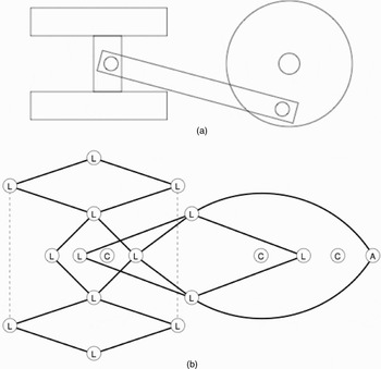
Archytas thus represents the intersections between the most basic elements of a 2-D line drawing—line segments, circles, and circular arcs—using this graph. It first reads in a drawing, fill patterns, and layering are ignored, so after preprocessing the drawing looks to Archytas like that of Figure 4a. Line segments are taken as maximally connected collinear segments, and likewise for cocircular connected arcs, whereas Archytas calculates all the intersection points between them. These elements form the vertices V of the line intersection graph, and the intersection points form the labels on the edges. Figure 4b shows an example of a line intersection graph.
(a) The piston and crankshaft drawing from Figure 1a with fill patterns and layering ignored as they are in Archytas and (b) its corresponding line intersection graph representation, where L stands for line segment, C for circle, and A for circular arc segment. Edge labels have been omitted to avoid clutter. In addition to what is shown, each bounded region (or face) is represented as a separate node (not shown) linked to the vertices and edges on its boundary. The dotted lines indicated collinear disconnected segments.

The line intersection graph represents the most basic topological information in the drawing. To reduce the search space for analogical mapping, Archytas augments this graph with additional spatial information. First, because each intersection is a pair of line (or arc) sets, Archytas adds a flag on each edge (i.e., intersection) indicating when those lines are perpendicular. This prevents Archytas from matching, say, a rectangle to a rhombus. Second, each topological face in the drawing bounded by a cycle of line and arc sets is represented as a special vertex linked to the points and lines on its boundary. This represents the planar dual of the input drawing (regarded as a plane graph). Archytas represents the intersections between the basic elements of a 2-D line drawing (line segments, circles, and circular arcs) using this augmented line intersection graph, which takes lines and arcs and circles nodes and intersections between them as labeled arcs.
2.2. Basic and composite shapes
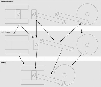
Depending on the perspective of a drawing, a particular component may be depicted by an actual shape, regarded as a set of connected lines or arcs, or not at all. Each component in the structural model is linked to a subgraph of the intersection graph called a “basic shape.” A connection between components in the model is a union of several entities, and so each connection is linked to a subgraph called a “composite shape.” A composite shape is a union of two or more basic shapes, forming a larger subgraph of the intersection graph. This forms the right half of the multilevel hierarchy shown in Figure 3. Figure 5 shows the decomposition of the drawing in Figure 4a into basic and composite shapes.
The breakdown of basic and composite shapes depicting the respective components and structural relations in the piston and crankshaft example of Figure 1a. The hollowed out shapes are as shown in Figure 4a. The hierarchy here mirrors that of the left-hand side of the model hierarchy in Figure 2.

The purpose of this two-level distinction, which will become clearer in Section 3 when we describe the algorithms, is to facilitate the reconstruction of a structural model from the information gleaned from overlapping shape mappings. It is because of this two-level distinction between basic and composite shapes, mirroring the two-level distinction between components and structural relations as shown in Figure 3, that we can reconstruct the model at all. Generally speaking, only one level of pattern (the shape patterns here) is insufficient to reconstruct a structural model: although we can match each pattern individually, the relationships between these instances of matched patterns are left open by the representation. Adding a higher level of composition over these patterns (the composite shapes, composed of basic shapes) allows the reasoner to fix not only the basic-level patterns in the target but their relationships as well. This process is described below in Section 3 in more detail.
2.3. Structural models
The structural model is a schema describing the components of a design, their properties, and their interrelationships. Structural relations are important: that two components have a certain physical relationship, say that a cylindrical piston is contained in a hollow cylinder, is an important fact that enables these two components to contribute to the overall functioning of the device. Thus, the ability to infer these relationships from a drawing is of critical importance to the task described in this paper. Therefore, our target representation is one of components, structural relations, and their properties and variable parameters.
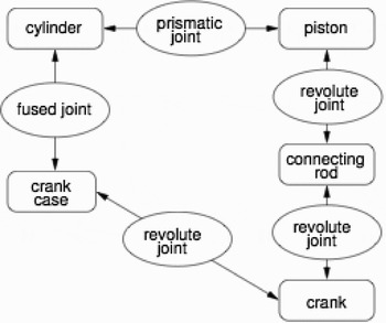
Figure 6 shows the structural model for the source drawing in Figure 1a, in which four of the five components and three of the five structural relations are linked respectively to basic and composite shapes in the drawing. The drawing depicts the following components, linking each component with a basic shape in the drawing:
• piston
• connecting rod
• crankshaft
• cylinder
An illustration of the structural model of the piston and crankshaft, where boxes represent components and ovals represent connections between components. Properties and variable parameters of components are specified in slot values for each component schema.

The crankcase is not depicted in this particular drawing. The following structural relations are depicted by composite shapes in the drawing:
• cylindrical joint between the piston and cylinder
• revolute joint between the piston and connecting rod
• revolute joint between the connecting rod and crankshaft
Each composite shape is again a union of the basic shapes of the components involved in the depicted structural relation. Thus, for instance, the revolute joint between piston and rod is depicted by the combination of those two shapes (the piston shape and the connecting rod shape). Because the crankcase is not depicted, the structural relations involving it are as well.
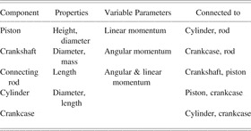
Table 1 shows an outline of the specification of the components. Each component has properties, which take static values (e.g., height, width, mass, etc.) and variable parameters, which have a type of either scalar or vector, and represent variables whose values change in the causal processes by which the device operates.
The properties and variable parameters of each component in the structural model of the piston and crankshaft device from Fig. 1a and the connected components

Connections are represented as schemas. Connections also have types indicating their degrees of freedom, if any (revolute joint, prismatic joint, fused or adjoined, etc.). Figure 6 shows the connections in the model of the piston and crankshaft example from Figure 1a.
3. ANALOGICAL MAPPING AND TRANSFER
The goal of the mapping stage is to align shapes in the source and target to facilitate the transfer of structure. However, at the start there are no shapes in the target, and so first Archytas attempts to align the individual shape patterns from the source with the augmented line intersection graph of the target. In particular, Archytas attempts to find mappings from each basic and composite shape to some subgraph of the target drawing's line intersection graph. Here, the mappings must be exact: each element of the shape pattern from the source must match, and so the algorithm is computing subgraph isomorphisms.
Recall the depicted components and the depicted structural relations from Figure 1a that are shown in Figure 5. To match these basic and composite shapes to Figure 1b, 1c, or 1d, Archytas begins by first finding subgraph isomorphisms for the composite shapes. If two composite shapes with a basic shape (i.e., a component) in common overlap as well in the target, then three connected components can be inferred in the target drawing by dividing the mapped composites into basic shapes.
3.1. Symmetric mappings
In matching shape patterns point by point to a drawing, a peculiar problem presents itself, one directly caused by our need to combine basic-level patterns into composite-level ones. In particular, shapes are often symmetric in various ways; for instance, a rectangle can be flipped or rotated to produce exactly the same shape. If we are searching point by point, what seems to be two different squares may actually be the same square discovered twice. That is to say, when searching point by point for a square we may find two different squares or we may find the same square we have already found, but with the pattern rotated 90°. When combining these patterns into composite shapes, if our composite pattern has two squares, it is important to distinguish genuinely new occurrences of this pattern from apparently different but actually symmetric matches to the same square, so that we can distinguish one shape occurrence from two. Most important, if we wish to transfer the representation of shapes from source to target (as we do in this work), symmetric mappings will produce identical results and so are equivalent: we do not care in what sequence we have discovered the four corners of a rectangle; as long as we have the same four corners each time, we have the same rectangle.
In Figure 5 the composite shape corresponding to the piston/cylinder connection has four potential mappings onto targets in Figures 1b and 1d and eight onto target 1c. The piston/connecting rod composite also has four mappings onto the target in Figure 1b and eight onto 1c. Although the points being mapped may be the same, not all of these mappings in fact overlap as they should. Thus, if our mapping algorithm happens to find a mapping for each of these that do not overlap with each other, we will find two pistons in Figure 1b instead of one, and four in Figure 1c instead of two.
All of the various mappings of a single shape to one particular set of lines and edges in the target are symmetric in the mathematical sense of that term, that is, they are permutations of each other. To see this, let m 1 and m 2 be two mappings from a single source shape. In general, these two mappings may map that shape to different regions of the target, but even if they map to the same region they may still be two different and therefore incompatible mappings. For instance, if a, b, c, and d are the corners of a rectangle in the source shape and w, x, y, and z are the corners of a similar one in the target, we might have
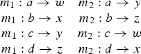
These two mappings are mathematically symmetric (thus permutations) and therefore equivalent: both are mapping the same shape to the same points in the target but in different orientations. This is important from the perspective of transfer, because the resulting target shape will be identical in either case.
This observation is critical: because of this transfer equivalency, we can group symmetric mappings together into sets. Archytas computes all mappings of each composite shape in the target, and divide them into these sets of symmetric mappings. For each such set, Archytas can compute the sets of symmetric basic shape mappings that each composite mapping can be divided into, and then transfer one composite shape in the target for each composite shape mapping set, and one basic shape for each basic shape mapping set. The algorithms are presented in the next section.
3.2. Shape mapping and transfer
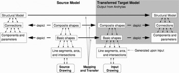
The goal of the shape transfer algorithm is to bring structure to the target drawing, that is, to use patterns to divide the lines and intersections into basic and composite shapes, which inform Archytas of the visual patterns in the target depicting components and structural relations. It is important to find all the mappings of a given shape so that all of the structural elements and relationships can be found. Each mapping group informs a new shape in the target, and the result is a shape-level mapping: a new mapping at the level of whole shapes rather than individual line segments and intersection points, which can now be discarded. From here, the transfer of structural elements (components and connections) can take place. This process is illustrated in Figure 7.
The multilevel hierarchy shown in Figure 2 is transferred onto the target by iteratively applying mapping and transfer methods at successively higher levels of abstraction, starting with basic and composite shapes and moving on to the transfer of structural components and connections until the model is complete.

The algorithm treats shape matching as one of satisfying constraints (Yaner & Goel, Reference Yaner and Goel2006). Each composite shape in the source is treated as a pattern, and the elements of the intersection graph in the target are matched to that pattern. Archytas attempts to find all consistent ways of matching a given pattern to a drawing, grouping symmetric mappings as discussed above so that “symmetric” means that the set of mapped points in two mappings are equal.
A constraint satisfaction problem is an assignment problem in which values are assigned to variables under some constraints. The algorithm we employ is a basic backtracking algorithm: potential values for each variable are tried in order, and when a conflict is found, that variable assignment is retracted and the algorithm backs up to the previous value or variable. In this application, the variables are the intersection points of the source composite shape. Two individual maps or assignments are consistent when they have exactly one line or arc set in common. Here, the map or assignment is actually a two-level assignment: there are two edge maps that each contain two line (or arc) set maps.
Basic backtracking is a robust method that has been discovered many times (e.g., Bitner & Reingold, Reference Bitner and Reingold1975), and has many variants (Kondrak & Van Beek, Reference Kondrak and Van Beek1997). One reason for selecting it is precisely because of these many variants and what is known about them: it is a straightforward matter to apply such optimization techniques as back-jumping or forward checking to a backtracking algorithm should the need arise to get additional performance from the search.
To constrain potential mappings, when two lines or intersection points are both on the boundary of a common face or region in the drawing, so must those they map to in the target. There are two additional constraints: perpendicular intersections map to perpendicular intersections but nonperpendicular intersections can map either to perpendicular or nonperpendicular intersections, and lines only map to lines, arcs to arcs, and circles to circles.
The outline of the algorithm is as follows:
1. Apply each composite shape, matching it to the target drawing as many times as possible using backtracking constraint satisfaction with the composite shape elements as variables, target intersection graph elements as values, and matching graph structure as constraints. Group symmetric composite shape mappings.
2. For each composite shape mapping, divide it into the appropriate basic shape mappings. Group symmetric basic shape mappings.
a. For each composite mapping set, record which basic shape mapping sets compose it.
b. If the composite mapping can be divided into basic shape mappings that are different from those of previous mappings in this set, save this division as a separate division of this mapping set into basic shape mapping sets.
3. For each set of symmetric composite shape mappings:
a. For each basic shape mapping set composing this composite shape mapping set, transfer one basic shape and map the old basic shape to this new basic shape.
b. Transfer the composite shape as a composition of the already transferred basic shapes, and map the old composite shape to this new composite shape.
4. Return this shape-level mapping.
Note that, in general, the shape-level mapping will not be one-to-one, and this is how the mapping from Figure 1a to 1c and 1d could be found.
3.3. Transfer of structural elements
Once Archytas has a mapping between the basic and composite shapes of the source and target drawings, it needs to transfer the structural elements from the source to the target. From these shape-level mappings one can hypothesize that if two shapes match (i.e., are mapped) then they should therefore depict the same component or connection. The steps are to begin with the mapped shapes and transfer the components and connections depicted by those mapped shapes, reconstructing the model iteratively.
As input to the structural transfer process, Archytas has a set of shape-level maps (recall from above that a mapping is composed of several individual maps of individual elements, in this case, whole shapes): basic shape maps and composite shape maps. Each one associates a source shape with a newly instantiated target shape. From each one we can hypothesize a structural element along with all its properties and variable parameters. The only major difficulty is that some components are undepicted. For instance, in Figure 1 none of the figures show the crankcase. Archytas transfers undepicted components based on their connections to depicted components: the crankcase is connected to the crankshaft and to the cylinder, which are depicted, so if we have a crankshaft and a cylinder we can hypothesize a crankcase. The output of this process is a new structural model of the target and a mapping from the source to the target that again may not be one-to-one.
The algorithm outline is as follows:
1. For each basic shape map, propose a new component in the target, and map the source component to this new target component.
2. For each composite shape map, propose a new structural relation in the target, and map the source structural relation onto this new target structural relation.
3. Transfer undepicted components: For each undepicted component in the source, propose one such component in the target and again map the source to the target component in the structure-level mapping.
4. Transfer undepicted structural relations: For each structural relation of a depicted and an undepicted component, propose one such structural relation in the target for every instance of that depicted component in the target. For instance, if component A is undepicted and connected to depicted component B, and A maps to A 1 and B maps to B 1 and B 2, connect A 1 in the target to both B 1 and B 2.
5. Remove disconnected chains: For each component C in the target, remove it and all of its structural relations if its source analog is connected to some other component that does not map to any component connected to C.
6. Return: The resulting component- and structural relation-level mapping from the old structural model to the newly instantiated target structural model.
Thus, the output of this process will be a new structural model of the target and a mapping from the source to the target model that may not be one-to-one.
There are two important constraints at work in this algorithm. The first is that, when transferring undepicted components, there is no guide as to how many times that component should be transferred (because the algorithm, as it is, simply iterates over the shape mapping but there are no maps for undepicted components!); thus, the system has little choice but to transfer it just once. Here, it remains an open question as to when one would transfer a given component more than once to a target. The answer must involve model-based reasoning at the level of the model itself, which is beyond the scope of this work.
The second issue has to do with what we term disconnected chains. The shape-mapping algorithm sometimes matches a shape more than once to overlapping patterns when it should map just once. The result of this process will be a component that is not properly connected to the rest of the model, hanging off like an extra loop on a chain, and so can simply be removed.
As an example of a disconnected chain, in transferring the model from Figure 1a to 1b, there was confusion with the connecting rod. In particular, because the intersections of the two lines with the piston are perpendicular, but in fact (although in the drawing it is hidden by layering), the rod continues upward some distance more, there was more than one mapping of the crankshaft/connecting-rod composite shape to the target. The result was one piston, one crankshaft, but two connecting rods, one of which connected the piston to the crankshaft as expected, the other that simply hung off the crankshaft and connected to nothing. This disconnected one was then removed by Archytas in disconnected chain removal.
4. EXPERIMENTAL RESULTS
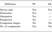
Archytas has been implemented in Common Lisp. There were 18 test drawings (including the two source drawings) across two domains: that of the piston and crankshaft (Fig. 1) and that of the door latch (Fig. 2). These drawings represented a range of kinds of differences between source and target, and the results are summarized in Table 2. In general, the implementation was quite fast, taking on average less than 20 s per example (almost all of that time was spent calculating the shape mappings in step 1 from Section 3.2). The drawings that were tested represent differences in the following:
1. the state of the device (e.g., the door latch pulled back vs. pushed out),
2. differences of the dimensions of particular shapes (e.g., thinner vs. thicker cylinder walls),
3. differences of orientation (such as a 90° rotation or a mirror image of a drawing),
4. differences in the 3-D perspective of the drawing,
5. differences of shapes depicting components (e.g., the cylinder as two parallel rectangles as in Fig. 1 or as one U-shaped polygon), and even
6. differences in the number of components (Fig. 1a vs. 1c or d, Fig. 2a vs. 2c).
The kinds of differences between the source and target drawings that Archytas can and cannot handle

PC refers to the differences tested in the piston and crankshaft examples, and DL refers to the door latch examples.
In general, the success or failure of the shape analogy determined the success or failure of the whole process because the SBF models that were constructed tended to nearly reflect the structure determined in this first stage. We found that differences of device state, dimension, and orientation were straightforward and presented little difficulty. This is to be expected from the nature of the representation of shapes; as such, changes do not alter the line intersection graph of a drawing. Changes in perspective or component shapes, however, were not handled, and changes in the number of components were sometimes handled well but sometimes were difficult. These were the most interesting cases that revealed the most about the methods. In what follows, we take 5 of the 16 target drawings for detailed analysis, the 5 shown in Figures 1b–d and 2b and 2c. We refer to these as PC1, PC2, PC3, DL1, and DL2, respectively.
4.1. Results of shape transfer methods
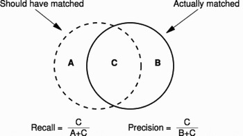
In the evaluation of shape transfer, the question is whether the “right” shapes are getting matched in the target drawing and transferred so as to enable transfer of the structural model. For instance, in the piston and crankshaft example, we would like the rectangle representing the crankshaft in the source to match the rectangles representing crankshafts in the target drawings, but not those representing the cylinder or the piston. To measure this, it is possible here to borrow from the information retrieval literature and make use of precision and recall (see Fig. 8). A “query” now is a source shape pattern, and the “responses” are the matching shapes in the target drawing. Thus, precision now asks, of those target shapes that actually matched, what proportion were correct; and, of those shapes in the target that should have matched, what proportion actually did?
Precision and recall are standard performance measures in information retrieval and can be generalized here for analogical comparison. It is possible to treat those forms in a target drawing that should have matched a given source shape pattern versus those that actually matched it, analogous to what should have versus actually did get retrieved for some particular query in an information retrieval system.

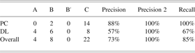
Formulating our questions this way, looking at the matching of composite shapes alone (because the shape analogy stage iterates over the composite shapes in the source), we get the results shown in Table 3. In addition, the disconnected chain removal stage of the structural transfer method also has the effect of removing the associated basic and composite shapes for the deleted components and connections. From the perspective of precision, this should have the effect of (hopefully) increasing the calculated precision. Thus, Table 3 also calculates a “Precision 2” from the modified numbers after disconnected chain removal. This also evaluates the effectiveness of disconnected chain removal to some extent.
A count of the precision and recall in the shape matching stage, for composite shapes only, by each domain
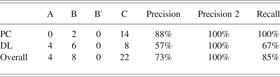
Here, as in Figure 8, column A counts the shapes that should have matched the drawing but did not, B counts those that did match but should not have, and C counts those that should have and did. Precision and recall are then calculated accordingly. In addition, B′ counts the reduced value of B after disconnected chain removal, and thus Precision 2 is the improved precision after this removal.
Overall precision was 73% before disconnected chain removal and 100% afterward, whereas recall was 85% across both domains. Looking at the individual domains, we see that the precision of 88% in the piston crankshaft examples became 100% after disconnected chain removal and the recall was 100%, which are perfect results for this domain. The door latch domain had surprisingly low 57% precision, which then jumped to 100% after disconnected chain removal; there were apparently many spurious composite shape mappings that were removed. The recall was, however, only 67%, so fully one-third of the expected target shapes were not being found by Archytas.
A precision or a recall of less than 100% in a system like this causes great difficulty: the shape transfer algorithm supplies a shape-level mapping to the structural transfer algorithm, and if that mapping is incomplete or has spurious correspondences, then the corresponding structural elements will be missing or spuriously transferred. Thus, it is worth investigating these numbers in more detail to attempt to determine where and when the breakdown is occurring.
The total and expected shapes for the three piston and crankshaft examples matched, as already established. The only redundant transfers were two extra shapes in the first example (PC1, removed by disconnected chain removal). In the door latch example, there were some extra shapes transferred in the first example (DL1, Fig. 2b, which showed a similar door latch in a different state) but then got removed in disconnected chain removal, and so the totals are exactly as expected. The poor performance comes in the second door latch example (DL2, Fig. 2c), which showed the two latches connected to a single cam.
It is worth investigating the door latch examples in more detail. We first use the double door latch example, the target in Figure 2b with 2a as the source. The cam/door composite and the bolt/door composite had no matches at all. Among the basic shapes the cam and the bolt did match (in the other composite shapes), so the problem was obviously the door. In this case, the shape of the door changed from source to target: instead of a C-shaped outline with two rectangles representing the plate through which the bolt moves, there were two such rectangle pairs on either side and the outline was no longer C shaped. No match was possible, so no match was found. Although this merely demonstrates already summarized results, it is an interesting and instructive illustration of the limitations of the method.
4.2. Results of structural transfer methods
In the transfer of structure, the algorithm iterates over the shape mapping provided by the previous stage. Therefore, if the shape mapping is correct, then the structural transfer will be correct as well. Hence, there were only two things to evaluate: the transfer of undepicted components and the removal of spuriously transferred components and connections.
The first of these is not as complex an issue as it might seem, and its limitations in Archytas were plainly established by the piston and crankshaft examples (the only ones that had undepicted components to transfer). In particular, in the third example (PC3, the piston and double crankshaft example, Fig. 1d) there were two crankshafts, but Archytas as always transferred the crank case only once. The question is, should there have been one or two crank cases in this example? It is not clear on the face of it what the answer is, and it must involve more complex model-based reasoning than Archytas engages in. With a more complex method for dealing with undepicted components the evaluation would necessarily be more complex. However, there is a single limitation and this example illustrates it.
The second of these is more interesting, and the results can be seen from the previous section. In particular, we see the disconnected chain removal working perfectly in the first piston and crankshaft example (Fig. 1b), as it does in the first door latch example. In the second door latch example, insofar as some of the components were transferred correctly, redundant transfers were removed successfully, so there were no remaining redundancies except the pair of cams. This is interesting: the component changed its shape as a result of performing two roles instead of simply one (that of moving two shafts), so the shape overlapped itself twice, and hence matched twice. The shapes overlapped means nothing in Archytas, so two components were transferred. The missing inference, that these are really one component, is really a very subtle inference and it is notclear when it should and should not be made. The problem of disconnected chain removal then appears to be more complex than has been assumed.
5. RELATED WORK
Börner (Reference Börner2001), Gross and Do (Reference Gross and Do2004), and Yaner and Goel (Reference Yaner and Goel2006) provide three methods for the task of analogical retrieval of drawings similar to a target drawing. In contrast, Archytas addresses the tasks of analogical mapping between a target and a source drawing, and transfer of the structural model from the source to the target.
Jupp and Gero's (Reference Jupp, Gero, Gero, Tversky and Knight2004) encoder–analyzer mechanism uses qualitative feature-based representations to recognize shapes and spatial relations in a 2-D drawing (the encoder) and decision tree learning for clustering design drawings (the analyzer). In contrast, Archytas not only recognizes shapes and spatial relations in a 2-D drawing but also recognizes the structural components and connections depicted by the shapes and spatial relations, and it uses analogical reasoning for this task.
Archytas addresses a different problem than Kramer's (Reference Kramer1993) geometric constraint engine (GCE). GCE takes as input a collection of geometric elements and a set of contraints between them and gives as output a configuration of the elements that satisfies all the contraints. In contrast, as we mentioned earlier, Archytas takes as input a configuration of geometric shapes and gives as output a label for each element in the configuration. Analogy-based comprehension is often presented as the problem of analogical mapping (e.g., Holyoak & Thagard, Reference Holyoak and Thagard1989; Falkenhainer et al., Reference Falkenhainer, Forbus and Gentner1990), and specifically that of structural alignment (where “structure” in this context means that of the representation itself, i.e., relational similarity as opposed to similarity of features). Certainly the transfer of some knowledge from source to target is always the goal of analogical inference, but when analogy is treated as structural alignment the tendency is to regard an analogy as an alignment or mapping In Archytas we see that the use of multiple levels of abstraction and aggregation requires a change in this view and, in particular, a whole mapping at one level can become a single match hypothesis (in structure-mapping engine terminology) at the next level. The role of mappings with respect to transfer thus changes when we consider working at several levels of abstraction simultaneously.
GeoRep (Ferguson & Forbus, Reference Ferguson and Forbus2000) is a diagrammatic reasoning system that takes an arbitrary 2-D line drawing as input and gives as output a description of the physical system depicted in the drawing. GeoRep is organized as a two-stage forward-chaining reasoner in which a line drawing passes through a domain-independent low-level relational describer that recognizes lines and polygons, and from there a high-level relational describer that applies a domain-specific rule set to produce a final representation of the content of the diagram. Applications of GeoRep typically derive structure from shape in the high-level relational describer; some applications have also used structure mapping (Falkenhainer et al., Reference Falkenhainer, Forbus and Gentner1990) for making further inferences by analogy largely at the level of structure. By contrast, our work infers both shape and structure by analogy.
Recently Klenk et al. (Reference Klenk, Forbus, Tomai, Kim and Kyckelhahn2005) developed a system for answering questions about simple mechanical devices using sketches. Their system has a user draw glyphs as separate entities and provide conceptual labels for these glyphs, so that the system need only compute the low-level visual relationships between the glyphs. It then uses structure mapping for making candidate inferences to complete the user-specified model for use by a qualitative physical reasoner to answer questions about the physical system. Unlike Archytas, Klenk et al.’s system does not actually recognize sketches or drawings. Further, their system does not use analogy to infer the entire model, but only to make inferences about an incomplete model given by the user, and to aid in answering a question.
6. CONCLUSIONS AND FUTURE WORK
In this paper we considered the task of acquisition of a structural model of a kinematics device from a 2-D line drawing of that device by constructing its model analogically. Our method of compositional analogy first constructs a representation of the lines and the intersections in the target drawing, then uses mappings at the level of line intersections to transfer shape patterns from the source case to the target, and finally uses the mappings at the level of shapes to transfer the structural model of the device. We demonstrated that by relaxing the constraints of one-to-one mapping and by interleaving the mapping and transfer processes at different levels of abstraction, a model can be inferred of the device depicted in a drawing by analogy without any predefined vocabulary of shapes beyond those that are already present in a known drawing.
Patrick W. Yaner is a Computer Scientist at LogicBlox, Inc. He attained BS degrees in applied mathematics and computer science from North Carolina State University in 2000 and a PhD in computer science from Georgia Institute of Technology in 2007. While he was a PhD candidate in the College of Computing at Georgia Tech, he studied artificial intelligence and cognitive science in the Design Intelligence Laboratory. Dr. Yaner's main research interests are visual reasoning and analogical problem solving.
Ashok K. Goel is an Associate Professor of Computer Science and Cognitive Science at Georgia Institute of Technology and Director of the Design Intelligence Laboratory in Georgia Tech's College of Computing. In 1998 he was a Visiting Research Professor at Rutgers University and a Visiting Scientist at NEC. Dr. Goel conducts research at the intersection of intelligence and design. He uses techniques from cognitive science, AI, and machine learning to address problems in design and design problems as sources for developing computational techniques for analogical reasoning, visual reasoning, and meta-reasoning. His current research focuses on multimodal reasoning in design by analogy and creative design.