1. Introduction
The upper limb rehabilitation robot was the product of the application of robotic technology in rehabilitation medicine, and has now become one of the effective technical ways to solve the contradiction between supply and demand of medical resources [Reference Jiang, Li and Lee1]. Over the past two decades, universities and rehabilitation medical institutions in domestic and foreign have successively carried out the research on the upper limb rehabilitation robot systems, and have achieved rich research results in robot configuration optimization and prototype design [Reference Pang, Wang and Wang2,Reference Nicholson-Smith, Mehrabi and Atashzar3]. However, some problems have arisen in the research process of rehabilitation robots and require further research. According to the experienced rehabilitation physicians, when the existing rehabilitation robots in clinical practice were performing rehabilitation tasks, physicians often assist patients in periodic training by holding the patient’s arm [Reference Thompson, Ranta and Porter4]. In addition, the assessment of the comfort of upper limb rehabilitation robots also seemed to have become a difficult problem. If these problems can be explained and quantified, it has very important practical significance for the research of rehabilitation robots.
The upper limb rehabilitation robot was a typical human-robot integrated electromechanical system. When the users were connected to the wearable element of the robot, a space multi-loop closed kinematic chain was formed between the human and the robot [Reference Jo5]. In the process of rehabilitation tasks, the transmission of force and movement were realized through the physical human-robot interaction at the connective interfaces [Reference Zhang, Lu and Wu6]. Due to the difference in the kinematics of the human-robot joints and the misalignment of the joint axes of the two, the DOFs of the closed chain mechanism was lost, which directly led to the variation of the human-robot interaction forces. If the axes of the human-robot joints were misaligned, the upper limb may be affected by the negative restraint forces while receiving the effective restraint forces. The negative restraint forces were superimposed with the internal forces (hyperstatic forces) that was not related to rehabilitation training in the closed-chain mechanism, which influenced the safety and comfort of the robot [Reference Brahmi, Saad and Luna7,Reference Sarac, Solazzi and Frisoli8]. At present, it can be seen from the literatures search that the relevant research on comfort performance evaluation was mainly concentrated in the field of cockpit and clothing, while there were few researches on the wearing comfort of robots [Reference Song, Pan, Xu and Li9–Reference Gudrun, Maria and Andrea11]. Liu et al. [Reference Liu12] assessed comfort by measuring body pressure and established a subjective evaluation standard for comfort using the Likert scale. Subsequently, Eom et al. [Reference Eom and Lee13] evaluated the comfort of the rehabilitation robot by measuring the surface temperature of the rehabilitation robot under two actions and using a 7-point Likert scale. Similarly, there were some studies that established comfort evaluation indicators by measuring the interaction forces between users and robots [Reference Freeman, Rogers and Hughes14,Reference Blank, French and Pehlivan15]. Related investigations suggested that the quantification of human-robot interaction forces seemed to have become one of the key elements in establishing a comfort index system [Reference Islam, Rahmani and Rahman16,Reference Moshaii, Moghaddam and Niestanak17]. If a method can be proposed to calculate the interaction forces between the robot and the user, it will be of great significance for the evaluation of comfort. However, it should be noted that the hyperstatic forces should not be included in the calculation of the human-robot interaction forces [Reference Ji, Shuai and Tao18]. Because excessive hyperstatic forces will significantly increase the restraint strength between the robot and the users, which will lead to limb injury [Reference Amertet19]. Through literatures search, the most important factor leading to the generation of hyperstatic forces was the misalignment of the human-robot joints rotational center. To weaken the hyperstatic forces between users and robots, researchers have proposed three solutions. The first approach was to introduce compliance in the robotic mechanism, which was solved by the flexible deformation of the actuator system. For example, the use of pneumatic muscles to actuate the robot or the use of elastic cables to transmit power [Reference Rahman, Rahman and Cristobal20,Reference Wu, Hornby and Landry21]. The second method was to add a support mechanism for local joint in the robot [Reference Stegall, Winfree and Zanotto22]. During the training process of the limbs, these mechanisms enabled the limbs to track the movement of the robot, thereby adjusting the joints axis between the robot and the limbs. A third method was to introduce a suitable number of passive DOFs into the robotic mechanism. According to the different introduction positions of the passive joints [Reference Jianfeng, Qiang and Chunzhao23,Reference Jianfeng, Qiang and Mingjie24], the robot mechanisms were divided into alignment-free mechanisms and self-tracking mechanisms. For the third method, the number of DOFs introduced into passive joints seemed to be the key to the investigation. If too many passive DOFs were introduced, the mechanism will become a redundant actuator mechanism. At this time, once the robot was actuated, the weak link of the mechanism will be deformed or even safety problems will occur. If the number of passive joints introduced was too small, the mechanism was an underactuated mechanism, and its movement will move in the direction of the minimum damping trend, and the movement trajectory will not be determined. Aiming at the number of passive DOFs, Nathanael et al. [Reference Jarrasse and Morel25] proposed a configuration synthesis method based on spatial rank analysis of movement and force. In addition, Li et al. presented a number synthesis method based on the activity analysis theory of spatial multi-loop closed chains [Reference Jianfeng, Ziqiang and Chunjing26]. Both configuration synthesis approaches implied that the 4-DOFs upper limb rehabilitation robot required to introduce 8 passive joints to reduce the hyperstatic forces. In recent studies, including those by Ref. [Reference Liang, Wang and Hou27], similar methods have been employed in lower limb rehabilitation robots to estimate human-robot interaction forces, offering promising results for real-time force estimation. However, applying such methods to upper extremity robots with distinct kinematic and dynamic properties remains a challenge. This work aims to extend the applicability of such approaches to upper limb rehabilitation robots by proposing an algorithm for estimating human-robot interaction forces in this context. In this paper, the third method was utilized to decrease the hyperstatic forces in the closed chain. In addition to the hyperstatic forces, it was necessary to define the effective interaction forces and the negative interaction forces. For example, when the shoulder joint was actuated by the robot and performed rehabilitation training according to a certain trajectory, the interactive forces that can drive the adduction/abduction and flexion/extension of the shoulder joint was called effective, and the interactive forces in other directions was called negative [Reference Jianfeng, Shicai and Leiyu28]. Furthermore, there was not much explanation for the phenomenon that doctors held the patient’s arm to assist the patient’s training when the rehabilitation robot performed rehabilitation tasks. To characterize this phenomenon, the Newton-Euler equations of dynamics were employed in this paper to quantify the internal forces at the joints. Although this method was cumbersome, it can clearly describe the variation law of internal forces between adjacent elements.
In this work, a novel 4-DOFs upper extremity rehabilitation robot mechanism is presented. On the basis of this robotic mechanism, an estimation algorithm of human-robot interaction forces is proposed, which is based on the Newton-Euler equation of dynamics. Then, a robot prototype was developed and a comparison experiment of human-robot interaction forces was performed. Finally, the experimental results are analyzed and discussed. The remainder of the paper is organized as follows. In Section 2, the kinematic model of the upper limb is described and a 4-DOFs robot mechanism is presented. And the estimation algorithm of human-robot interaction forces is proposed, which is based on the Newton-Euler dynamic equation. The measurement experiment of human-robot interaction forces is carried out. In Section 3, the analysis and discussion of the human-robot interaction forces comparison experiment is provided. Finally, conclusions as well as potential directions for future work are given in Section 4.
2. Mechanism configuration of an upper limb rehabilitation robot
2.1. Kinematic model of the upper extremity
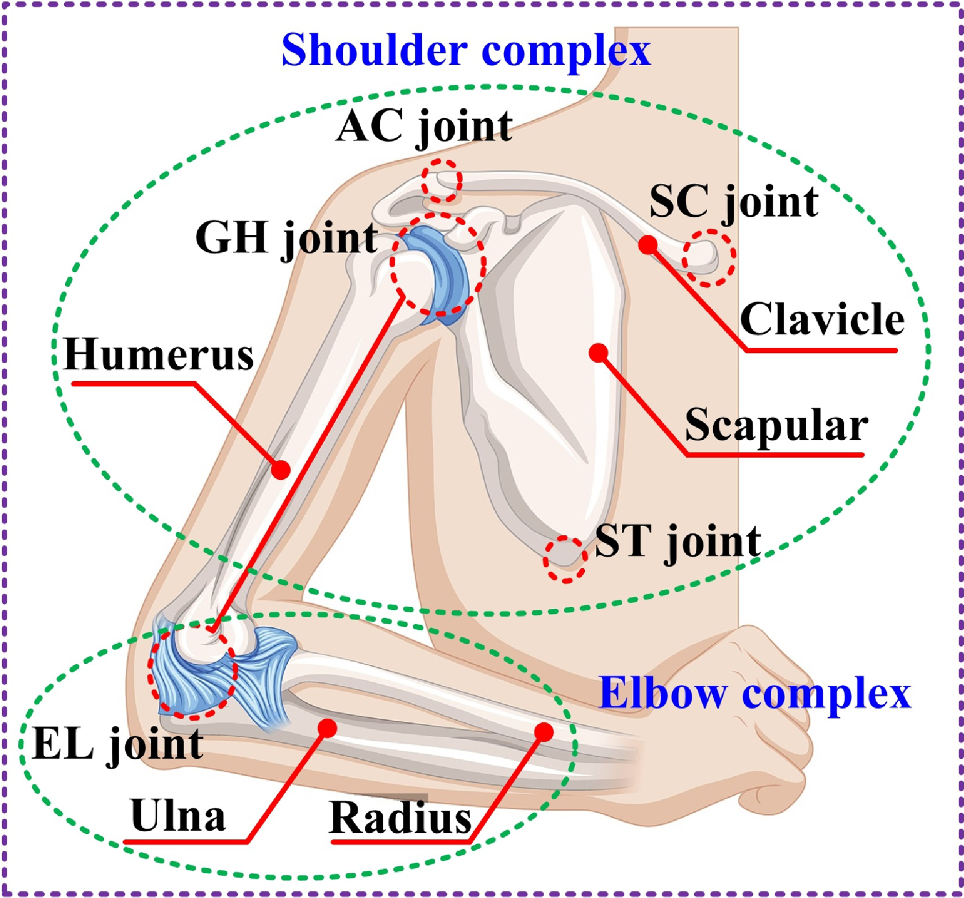
The kinematic model of shoulder complex is the basis for characterizing the dynamic behavior of the upper extremity, and it is also one of the urgent problems to be solved in the dynamic analysis of the upper extremity rehabilitation robot [Reference Niyetkaliyev, Hussain and Jamwal29]. Due to the complexity of the shoulder structure [Reference Chunzhao, Mingjie and Jianfeng30,Reference Jianfeng, Chunzhao and Mingjie31], it is difficult to establish a kinematic model that can characterize its biological properties and characteristics. According to human anatomy studies, the upper extremity includes the shoulder and elbow complexes, as shown in Figure 1. The skeletal-joints structure of the shoulder complex is mainly composed of the sternum, clavicle, scapula, and humerus, as well as some joints, which are the sternoclavicular (SC), acromioclavicular (AC), glenohumeral (GH), and scapulothoracic (ST) joints.
The anatomic structure of the upper extremity.

Heretofore, researchers have established several different shoulder kinematic models based on the anatomical structural features and kinematic properties of the human shoulder combined with the detection and analysis of limbs segment movement information. From the investigation of the shoulder kinematics model, the consensus of the researchers is that the movement of the shoulder is composed of the 3-DOFs rotation of the GH joint and the movement of the shoulder girdle, but there is a definite coupling relationship between the two [Reference Jianfeng32,Reference Hamming, Braman and Phadke33]. Among them, the rotational movement of the humerus around its axis is independent of the shoulder girdle movement, while the rotation in the other two directions is coupled with the shoulder girdle movement, resulting in a change in the rotational position of the GH joint. Therefore, the kinematics of the shoulder complex can be equivalent to a 3-DOFs GH joint with a floating rotational center, and the position of the rotational center of the GH joint is certain coupled relationships with the elevation angle of the upper arm. In this context, the researchers analyzed and modeled the coupling relationships of the shoulder. Paper [Reference Klopcr, Tomsic and Lenarcic34] synthesized the coupling relationships between the rotation angle of the GH joint and the shoulder girdle movement based on the movement information of the upper arm in the 0°, 45°, 90° and 135° elevation planes [Reference Klopcr, Tomsic and Lenarcic34]. However, since the detection results only correspond to the movement configuration of the upper arm in the four elevation planes, the applicability of the obtained movement coupling relationships is limited to a certain extent. Paper [Reference Newkirk, Tomšič and Crowell35] described the movement of the shoulder girdle relative to the humerus in the whole domain [Reference Newkirk, Tomšič and Crowell35], and presented the coupling relationships between the movement of the shoulder girdle and the GH joint. In our work, the kinematic model of the shoulder joint and the coupling relationships directly adopted the conclusions of the paper [Reference Newkirk, Tomšič and Crowell35].
The skeletal-joints structure of the elbow complex is mainly composed of the humerus, ulna, and elbow joints. Existing studies have shown that the elbow joint is a 2-DOFs hinge joint, which realizes the rotational movement and translational movement of the elbow respectively. However, due to the small translational displacement of the elbow joint, translational movement is usually ignored in the elbow joint model [Reference Bottlang, Madey and Steyers36,Reference Sheikhzadeh, Yoon and Pinto37]. This simplification is essential for reducing the computational complexity in dynamic analysis and allows us to focus on the primary rotational movement of the elbow. Given that the translational displacement is minimal, this assumption does not compromise the overall accuracy of the kinematic model. Several previous studies have demonstrated the validity of such simplifications in similar rehabilitation robotic systems [Reference Schiele and Helm38–Reference Velden, Onneweer and Haarman41]. Therefore, the elbow joint is equivalent to a 1-DOF rotational joint, and this simplification serves as the basis for the dynamic analysis of the upper limb rehabilitation robot.
2.2. Description of the robot mechanism configuration
The upper limb rehabilitation robot is a typical human-robot integrated electromechanical system. After the human-robot wearable connection, the robot and the upper extremities form a spatial multi-loop closed kinematic chain. During the rehabilitation training process, the power transmission and movement coordination are realized through the physical human-robot interaction at the connection interfaces. To guarantee the smoothness of human-robot interaction and obviate secondary injury of the affected limbs, excessive constraint forces and large human-robot relative movement deviation should not be generated between the robot and the upper extremity. Nevertheless, due to the misalignment of the axes (center) between the upper extremity joints and the robot joints, some problems have arisen in the rehabilitation training of the robot. The misalignment of the axes (center) will lead to the generation of hyperstatic forces at the human-robot interfaces. The hyperstatic forces can significantly increase the restraint strength between the robot and the limbs, and lead to decreased comfort or safety problems. The introduction of passive DOFs has become one of the most effective ways to reduce hyperstatic forces. The latest research suggested the introduction of passive joints has resulted in a reduction of up to 59% in hyperstatic forces [Reference Jianfeng, Qiang and Mingjie24].
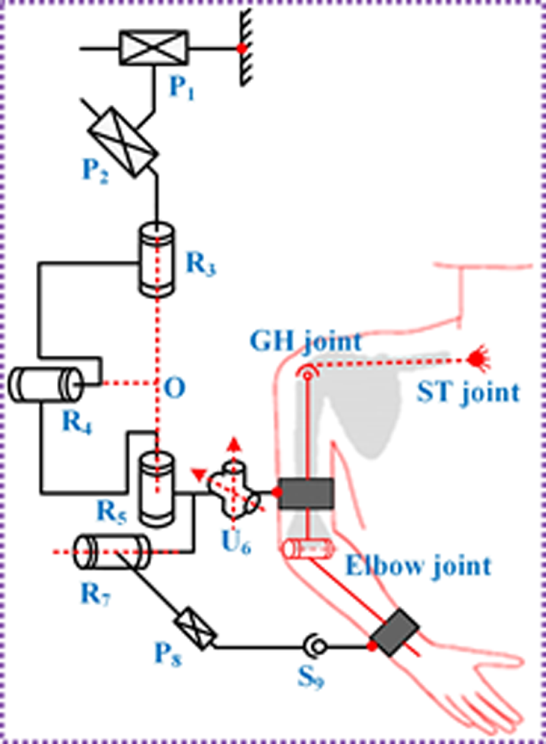
Based on the kinematic model of the upper extremity in Section 2.1, the GH joint is equivalent to a spherical joint with a floating rotational center, and the elbow joint is regarded as a revolute joint. The research conclusion of paper [Reference Jianfeng, Ziqiang and Chunjing26] indicated that when the upper extremity is used as a 4-DOFs kinematic chain, eight passive DOFs need to be added into the robot configuration to weaken the hyperstatic forces. In addition, based to the number of passive joints introduced in each closed-loop chain, the 4-DOFs compatible robot configurations can be classified into the following three categories, as shown in Table 1. In the Table 1, fs and fe represent the number of DOFs introduced by the GH joint sub-chain and the number of DOFs added by the elbow joint sub-chain, respectively. Subsequently, paper [Reference Cao, Li and Dong42] conducted an analysis and research on the relative movement offsets for the three types of robot configurations, and the research results suggested that the second category of robot configuration has better movement consistency [Reference Cao, Li and Dong42]. Therefore, the robot configuration investigated in this paper will be selected from the second category of configuration. In the paper, three prismatic DOFs, one spherical joint and a universal joint were introduced to weaken the adverse effects of robotic over-constraints on upper extremity rehabilitation. The DOFs distribution characteristics of the robot mechanism are shown in Figure 2, and the arrangement features of passive DOFs are described below. The passive prismatic DOFs P1 and P2 are perpendicular to each other in the horizontal plane, which can track the rotation center of the GH joint at any position in the horizontal plane. In addition, since the P1 and P2 are directly connected to the base, part of the gravity of the upper extremity rehabilitation robot can be borne by the base, effectively decreasing the load and restraint of the affected limbs. The passive prismatic DOFs P8 is parallel to the axis of the forearm, so as to balance the axial load of the forearm. The universal joint U6 and the spherical joint S9 are directly connected to the upper arm and forearm respectively. This arrangement not only ensures that the robot mechanism is compatible with the upper extremity, but also does not make the passive connection sub-chains too long, thereby improving the transmission of movement and force.
The 4-DOFs Robot Configurations Compatible with the Upper Extremity

Schematic diagram of the robot mechanism.

3. Derivation of human-robot interaction forces for robot
Dynamics is to study the mapping relationship between the movement of the robot joints and the actuating forces (moment) required by the joints [Reference Zhong, Dongkai and Zhao43]. In this paper, the Newton-Euler method is used to analyze the dynamics of the upper extremity rehabilitation robot. This method is a recursive way to establish dynamic model, which can clearly describe the internal forces variation between adjacent members. For rehabilitation robots, the issue of comfort and safety has always been a key consideration. If the variation of the interaction forces at the connection interfaces can be quantified, it will play a very important role in the safety of the robot [Reference Wang44]. The research focus of this chapter is on the characterization of the human-robot restraint forces, which is provided a reference for the definition of the comfort performance.
3.1. Determination of inertial forces
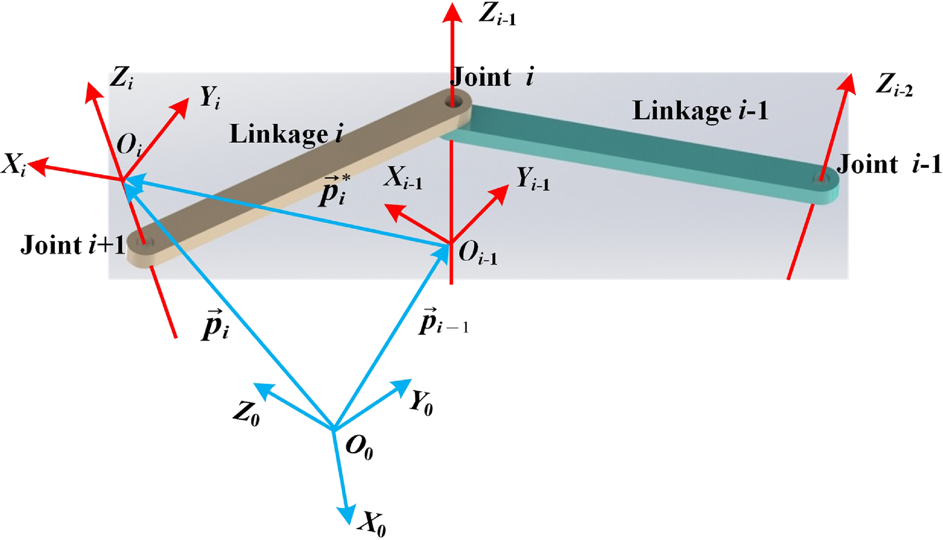
The fundamental of Newton-Euler dynamics is to transform the dynamic problem into the statics equilibrium problem through D’Alembert’s principle. When using the Newton-Euler method to establish the dynamic equation of the human-robot kinematic chain, it is necessary to analyze the kinematic relationship between adjacent linkages. The schematic diagram of the movement relationship between adjacent members is shown in Figure 3. In Figure 3, the coordinate system O i-X iY iZ i is a standard orthogonal coordinate system, O-X 0Y 0Z 0 is an inertial coordinate system, and the position of the O i relative to the O and O i-1 is represented by
 ${\mathord{\buildrel{\lower3pt\hbox{$\scriptscriptstyle\rightharpoonup$}} \over p} _i}$
and
 $ {\mathord{\buildrel{\lower3pt\hbox{$\scriptscriptstyle\rightharpoonup$}} \over p} _i} $
, respectively. Based on the derivation process of Newton-Euler method, the derivation of the velocity, acceleration, inertial force, and inertial moment between adjacent linkages is as follows. The derivation results of angular velocity, angular acceleration, velocity, acceleration, acceleration at the center of mass, inertial force, and inertial moment are shown in Eqs. (1) to (7), respectively.
 $${\vec \omega _{i + 1}} = \left\{ {\begin{array}{*{20}{c}}{\vec R_i^{i + 1}{{\vec \omega }_i} + {{\dot q}_{i + 1}}{{\vec k}_i}} \\ {\vec R_i^{i + 1}{{\vec \omega }_i}} \\ \end{array} } \right.$$
 \begin{align} \dot{\vec{\omega}}_{i+1}=\left\{\begin{array}{c}\vec{R}_i^{i+1}\dot{\vec{\omega}}_{i}+\ddot{q}_{i+1}\vec{k}_i+\vec{R}_i^{i+1} \big(\vec{\omega}_i\times\dot{q}_{i+1}\vec{k}_i \big)\\[3pt] \vec{R}_i^{i+1}\vec{\omega}_i\end{array}\right. \end{align}
 \begin{align} {\vec{v}}_{i+1}=\left\{\begin{array}{c}\vec{R}_i^{i+1}\big({\vec{\omega}}_i\times\vec{p}_{i+1}+\vec{v}_i \big)\\[3pt] \dot{q}_{i+1}\vec{k}_i+\vec{R}_i^{i+1}\big(\vec{\omega}_i\times\vec{p}_{i+1}+\vec{v}_i \big)\end{array}\right. \end{align}
 \begin{align} \dot{\vec{v}}_{i+1}=\left\{\begin{array}{l}\vec{R}_i^{i+1}\left[{\dot{\vec{\omega}}}_i\times\vec{p}_{i+1}+\vec{\omega}_i\times \big({\vec{\omega}_i\times\vec{p}_{i+1}} \big)+\dot{\vec{v}}_i \right]\\[3pt]\ddot{q}_{i+1}\vec{k}_i+2\vec{\omega}_{i+1}\times \big(\dot{q}_{i+1}\vec{k}_i \big)\\[3pt] +\vec{R}_i^{i+1}\left[\dot{\vec{\omega}}_i \times \vec{p}_{i+1}+\vec{\omega}_i\times \big(\vec{\omega}_i\times\vec{p}_{i+1} \big)+\dot{\vec{v}_i} \right]\end{array}\right. \end{align}
 \begin{align} \dot{\vec{v}}_{C,i+1}& =\dot{\vec{v}}_{i+1}+\dot{\vec{\omega}}_{i+1}\times\vec{r}_{C,i+1} \nonumber \\[3pt] & \quad+\vec{\omega}_{i+1}\times \big(\vec{\omega}_{i+1}\times\vec{r}_{C,i+1} \big) \\[-24pt] \nonumber \end{align}
 \begin{align} {\vec{f}}_{C,i+1}={m}_{i+1}\dot{\vec{v}}_{C,i+1} \\[-24pt] \nonumber \end{align}
 \begin{align} \vec{n}_{C,i+1}=\vec{I}_{C,i+1}\dot{\vec{\omega}}_{i+1}+{\vec{\omega}}_{i+1}\times(\vec{I}_{C,i+1}\vec{\omega}_{i+1}) \\[-6pt] \nonumber \end{align}
The schematic diagram of the movement relationship between adjacent members.

In formulas (1) to (4), the joint i corresponding to the first component is a revolute joint, and the joint i corresponding to the second element is a prismatic joint. The parameters expressed in the formula are all relative to the inertial coordinate system, the
 $ \dot q $
is the generalized coordinate, indicating the variable of joint i. The
 $ {\vec p_{i + 1}} $
is the position vector of the origin of the frames {i+1} in the frames {i}, which is constant. The
 $ \vec R_i^{i + 1} $
is the transformation matrix from coordinate system {i} to coordinate system {i+1}; The
 ${\vec \omega _{i + 1}}$
and
 ${\dot{\vec{\omega}}} _{i + 1}$
represent the angular velocity and angular acceleration of linkage i+1, respectively, which are vectors described in the coordinate system {i+1}; The
 ${\dot{\vec{v}}}_{i + 1}$
and
 ${\dot{\vec{v}}}_{C,\,i + 1}$
denote the acceleration of the linkage i+1 and the acceleration at the center of mass, respectively; The
 ${m_{i + 1}}$
and
 ${\vec I_{C,\,i + 1}}$
represent the mass of the linkage i+1 and the inertia tensor at the center of mass, respectively;
 ${\vec f_{C,\,i + 1}}$
and
 ${\vec n_{C,\,i + 1}}$
represent the inertial force and inertial moment respectively, which are both at the center of mass of the linkage i.
3.2. Solving of human-robot physical interaction forces
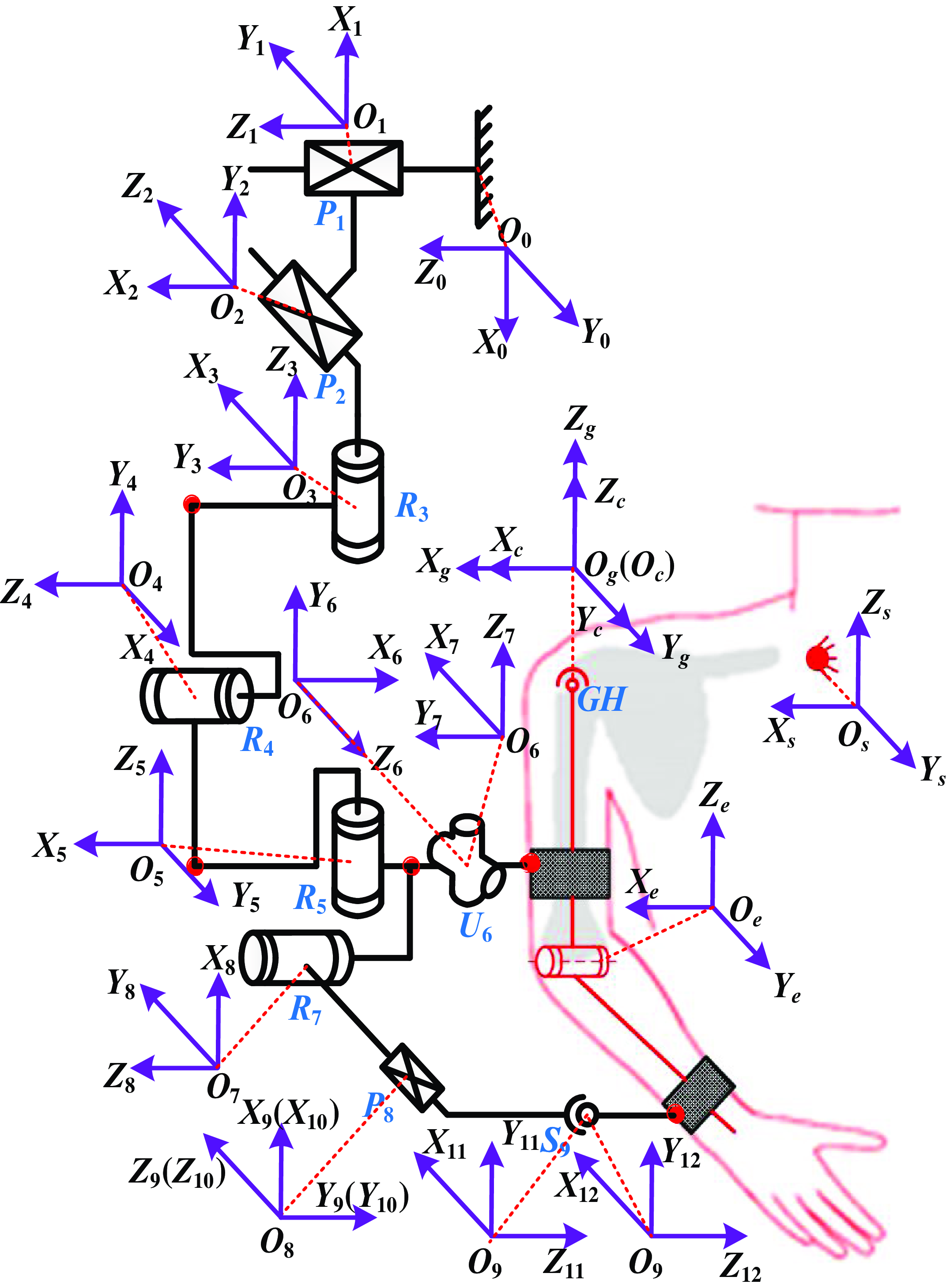
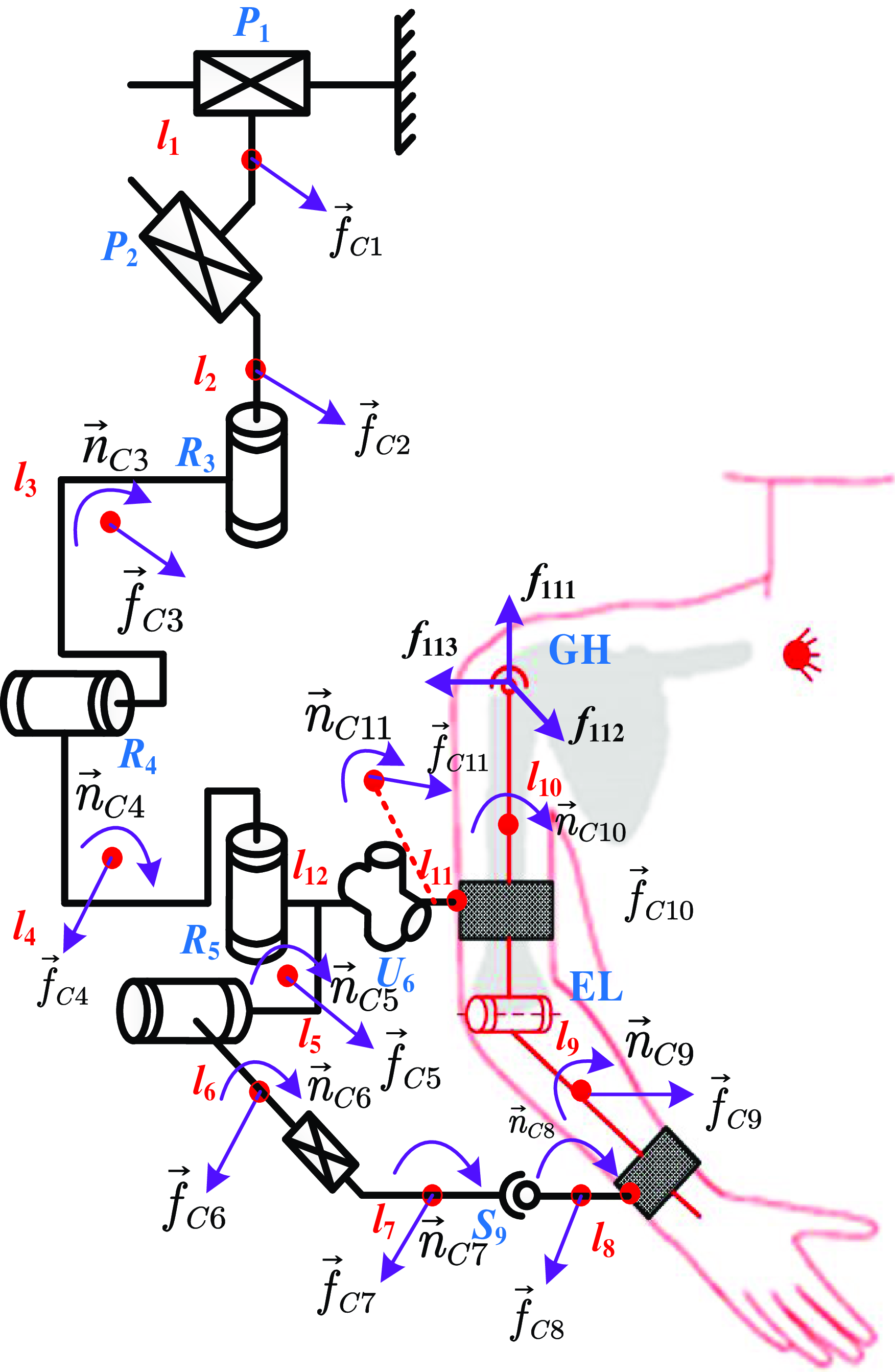
In this section, based on the proposed robot mechanism, a solution approach of the physical human-robot interaction forces is presented. To facilitate the solution of interaction forces, some coordinate systems and inertial forces are defined, as shown in Figures 4 and 5, respectively. Among them, O 0-X 0Y 0Z 0 is the inertial coordinate system, and frame O i-X iY iZ i is the local coordinate system of the linkage i.
Schematic diagram of closed chain coordinate systems.

The force analysis diagram of closed chain.

As shown in Figure 5, it is assumed that the entire human-robot closed chain is unlocked at the joint GH. According to the description in Section 2.1, the kinematic model of the joint GH is characterized as a spherical joint with a floating rotational center. Based on the kinematic characteristics of the spherical joint, the joint GH will be affected by
 $ {\vec f_{11}} = {\left[ {{f_{113}},\,{f_{112}},\,{f_{111}}} \right]^T} $
during rehabilitation tasks, as shown in Figure 5. Assume that at the initial moment, the velocity, angular velocity, acceleration, and angular acceleration at the base of the robot are
 $ \vec v = {\left( {0,\,0,\,0} \right)^T} $
,
 $ {\vec \omega _0} = {\left( {0,\,0,\,0} \right)^T} $
,
 $ {\dot{\vec{v}}}_{0} = {\left( {g,\,0,\,0} \right)^T} $
, and
 $ {\dot{\vec{\omega}}}_{0} = {\left( {0,\,0,\,0} \right)^T} $
, respectively. According to formulas (1) to (7), the inertial force and inertia moment of each member can be easily solved.
A phenomenon can be found by observing the entire human-robot closed chain. To quantitatively calculate the interaction forces at the connection interfaces, it is imperative to determine the internal force
 ${\vec f_{11}}$
borne by the GH joint. To determine the magnitude of
 ${\vec f_{11}}$
, additional constraint equations need to be established. According to the force analysis schematic diagram of the closed chain, the restraint internal forces at the GH joint and all the inertial forces in the robot mechanism are in balance together. The establishment of the equilibrium equation is as follows:
 \begin{align} \sum\limits^{11}_{i-1} \vec{f}_{ci} + \vec{f}_{11} = 0 \end{align}
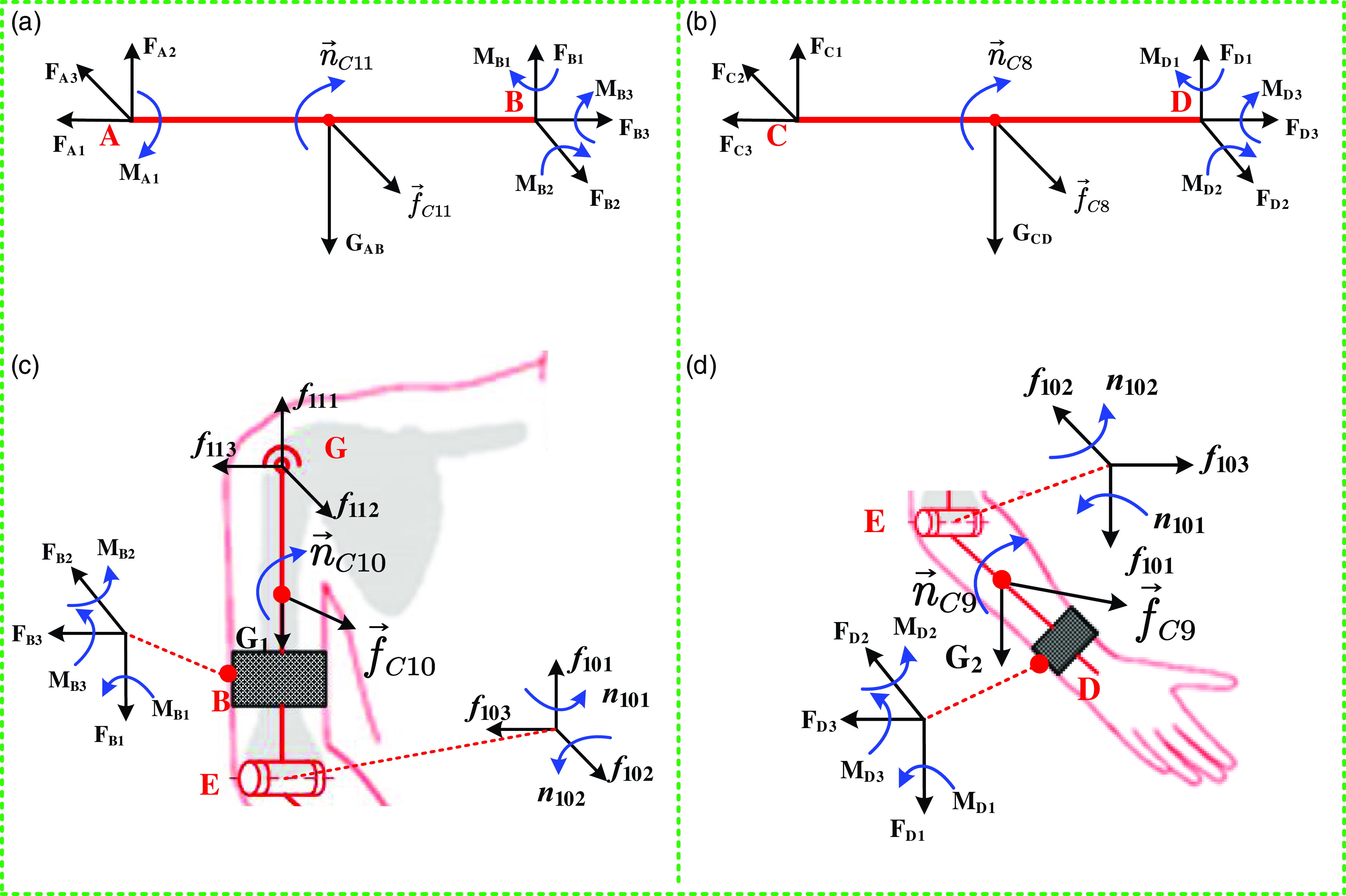
Let B be the contact point between the robot mechanism and the upper arm, and A be the center of the universal joint U6. To characterize the constraint force relationship between the upper arm and the robot mechanism, the force analysis of the linkage AB is carried out, and the force analysis is shown in Figure 6(a). It can be seen from Figure 6(a) that the linkage AB maintains a balance under the action of gravity GAB, the force on the universal joint, the inertial forces, and the human-robot interaction forces of the upper arm. The presented static equilibrium equation is shown in formula (9):
 \begin{align} \left\{\begin{array}{l}\sum\limits_{i=1}^3\vec{F}_{Ai}+\sum\limits_{i=1}^3\vec{F}_{Bi}+\vec{G}_{AB}+\vec{f}_{C11}=0\\[3pt] \vec{M}_{A1}+\sum\limits_{i=1}^3\vec{M}_{Bi}+\vec{n}_{C11}+\sum\limits_{i=1}^3(\vec{r}_{Bi}\times\vec{F}_{Bi})\\[3pt] +\sum\limits_{i=1}^3(\vec{r}_{Ai}\times\vec{F}_{Ai})+\vec{r}_{AB}\times\vec{G}_{AB}+\vec{r}_{C11}\times\vec{f}_{C11}=0\end{array}\right. \end{align}
The schematic diagram of force analysis for linkage AB (a), linkage CD (b), upper arm (c), and forearm (d).

Where
 ${\vec r_\phi }$
represented the vector radius of forces
 ${\vec F_\phi }$
relative to the fixed coordinate system. Subsequently, the force analysis of the upper arm is presented, and the force analysis diagram is shown in Figure 6(c). According to Figure 6(c), the static equilibrium equations of the upper arm can be listed as:
 \begin{align} \left\{\begin{array}{l}\sum\limits_{i=1}^3\vec{F}_{11i}+\sum\limits_{i=1}^3\vec{F}_{Bi}+\sum\limits_{i=1}^3\vec{f}_{10i}+\vec{G}_{1}+\vec{f}_{C10}=0\\[3pt] \sum\limits_{i=1}^3\vec{M}_{Bi}+\vec{n}_{C10}+\sum\limits_{i=1}^2\vec{n}_{10i}+\sum\limits_{i=1}^3 \big(\vec{r}_{BC10i}\times\vec{F}_{Bi} \big)\\[3pt] +\sum\limits_{i=1}^3 \big(\vec{r}_{GC10}\times\vec{f}_{11i} \big)+\sum\limits_{i=1}^3 \big(\vec{r}_{EC10}\times\vec{f}_{10i} \big) =0\end{array}\right. \end{align}
Similarly, let D be the contact point between the robot mechanism and the forearm, and C be the center of the spherical joint S9. The force analysis of the linkage CD is shown in Figure 6(b). According to the principle of statics, the equilibrium Eq. (11) can be derived:
 \begin{align} \left\{\begin{array}{l}\sum\limits_{i=1}^3\vec{F}_{Ci}+\sum\limits_{i=1}^3\vec{F}_{Di}+\vec{G}_{CD}+\vec{f}_{C8}=0\\[3pt]\sum\limits_{i=1}^3\vec{M}_{Di}+\vec{n}_{C8}+\sum\limits_{i=1}^3 \big(\vec{r}_{Ci}\times\vec{F}_{Ci} \big)\\[3pt]+\sum\limits_{i=1}^3 \big(\vec{r}_{Di}\times\vec{F}_{Di} \big)+\vec{r}_{CD}\times\vec{G}_{CD}+\vec{r}_{C8}\times\vec{f}_{C8}=0\end{array}\right. \end{align}
Afterwards, the forces analysis of the forearm is shown in Figure 6(d). The forearm is in balance under the action of forces and moments, and the static equilibrium equation is as follows:
 \begin{align} \left\{\begin{array}{l}\sum\limits_{i=1}^3\vec{f}_{10i}+\sum\limits_{i=1}^3\vec{F}_{Di}+\vec{G}_{2}+\vec{f}_{C9}=0\\[3pt]\sum\limits_{i=1}^3\vec{M}_{Di}+\vec{n}_{C9}+\sum\limits_{i=1}^2\vec{n}_{10i}+\sum\limits_{i=1}^3 \big(\vec{r}_{Di}\times\vec{F}_{Di} \big)\\[3pt]+\sum\limits_{i=1}^3 \big(\vec{r}_{Ei}\times\vec{f}_{10i} \big)+\vec{r}_{G2}\times\vec{G}_{2}+\vec{r}_{C9}\times\vec{f}_{C9}=0\end{array}\right. \end{align}
Substitute the dimensional parameters and inertia parameters of the human-robot closed chain, as well as the angular displacement, angular velocity, and angular acceleration of the upper limb movement into formulas (8) to (12), and the variation rules of the human-robot interaction forces of the upper arm and forearm can be calculated respectively.
4. Measurement experiment for human-robot interaction forces
4.1. Presentation of robot prototype
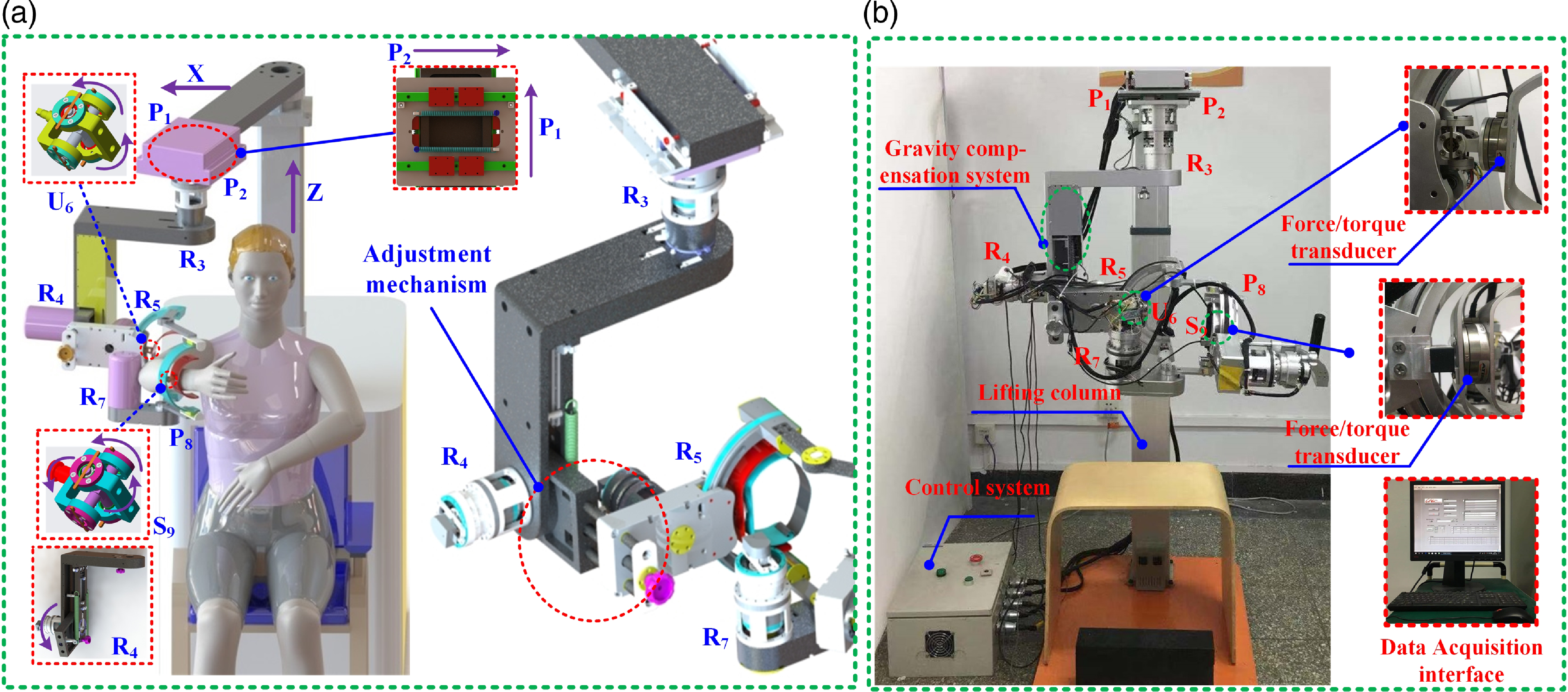
According to the kinematics configuration of the rehabilitation robot mechanism shown in Figure 2, the CAD (Computer Aided Design) model design and prototype development of the upper extremity robot are carried out, as shown in Figure 7. The robot prototype is currently located in the College of Mechanical Engineering and Applied Electronics Technology at Beijing University of Technology, and the prototype possesses the following characteristics. Firstly, the robot prototype consists of active joints and passive joints, in which the active joints R3, R4, and R5 assist the GH joint to achieve adduction/abduction, flexion/extension and internal/external movements. The active joint R7 assists the elbow joint to complete the flexion/extension of the forearm. Secondly, passive joints P1 and P2 can track the movement of the GH joint in the horizontal plane and are connected to the base, so that the connecting sub-chain is shortened and can transmit the gravity of the mechanism to the support. Passive joint P8 relieves axial forces caused by wearing deviations. In addition, the rehabilitation robot has the function of swapping left and right hands. It can realize the rehabilitation task of a single joint, and can also realize complex rehabilitation training of multiple joints corresponding to the daily actions of the human body, such as drinking, touching the shoulders, eating, or combing, etc. Finally, when designing the robot prototype, mechanical limiters were installed to restrict the movement range of each active joint to guarantee the safety of patients during the rehabilitation training process. Compared with the existing wearable rehabilitation robot, the designed robot has the following excellent performance: (1) The robot has compact structure, small volume and weight, and its rigidity meets the requirements of rehabilitation movement. (2) The left and right hands can be easily interchanged without disassembling the device, which can satisfy the rehabilitation needs of different affected limbs. (3) The robot implements the compatibility between the robot and the upper extremities, and improves the comfort during the rehabilitation training. (4) The robot uses a gravity balance system to eliminate the gravitational moment of the joints, thereby reducing the weight of the actuator.
The CAD model of the rehabilitation robot (a) and the prototype of the rehabilitation robot (b).

4.2. The measurement for interaction forces
In the acquisition experiment of this paper, A six-axis force/torque transducer (Mini45-SI-145–5, ATI, USA) was utilized to measure the human-robot interaction forces. The sensors were introduced between the robot and the upper extremity (immobilized within the robot), and the data is transmitted to the host computer via USB (Universal Serial Bus) using the acquisition card, as shown in Figure 7(b). Seven healthy volunteers without neurological, cardiopulmonary, and upper extremity musculoskeletal diseases participated in this experiment, and all volunteers were from Beijing University of Technology. In addition, the upper extremity parameters of the volunteers were measured and registered in real-time by professionals in the biomechanics laboratory. Before the experiment, the volunteers performed experiments with their right arm, and informed consent was given to each volunteer.
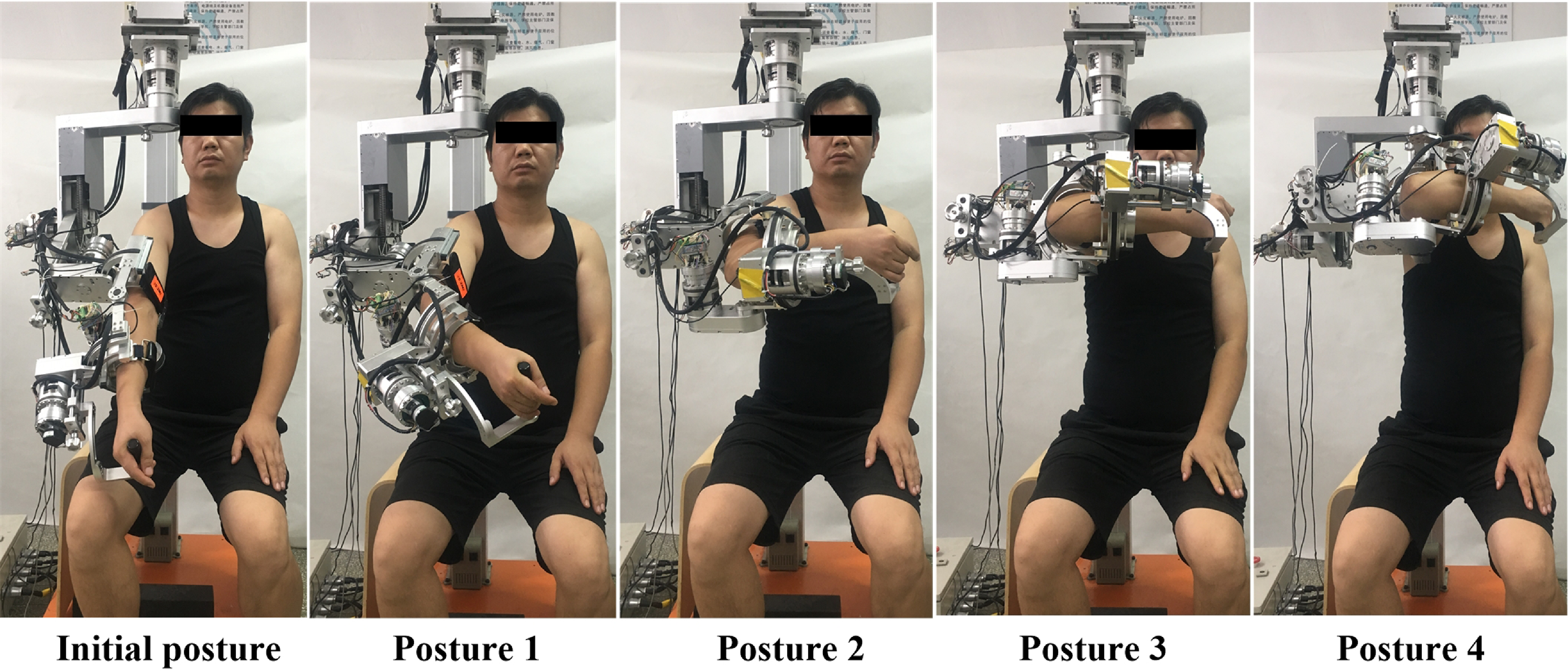
To quantitatively measure the human-robot interaction forces, a series of experiments were conducted using the designed upper extremity robotic device. To minimize experimental bias, several key principles were established to ensure consistency across all trials. Firstly, all initial conditions should be identical before the experiment starts. For example, the conformity of the volunteers and upper limb robot configuration and initial pose. The rehabilitation robot used in this experiment is typically characterized by self-aligning properties, as detailed in Ref. [Reference Jianfeng, Qiang and Chunzhao23]. This mechanism configuration allows for approximate alignment of the volunteers’ joint centers during initial setup, with the robot automatically adjusting to ensure optimal positioning throughout the rehabilitation process. This feature reduces the impact of human-exoskeleton joint misalignment on the experimental results. In addition to addressing joint misalignment, we incorporated several other features to accommodate variations in the volunteers’ body builds: (1) The robot includes an adjustable rotary table, allowing it to be used for both left and right upper limbs; (2) As shown in Figure 7(a), a manual adjustment button is included to account for different upper limb sizes among volunteers. These features ensure that the robot can be tailored to fit volunteers of varying body types. (3) To enhance safety, the range of motion for each joint is slightly restricted to remain within the physiological limits, and mechanical limit switches have been installed to prevent excessive joint movement. (4) High-precision encoders are embedded in each active joint to accurately measure joint angles and monitor auxiliary movements and forces [Reference Jianfeng, Qiang and Mingjie24]. Secondly, consistency in the data sampling process during the measurement period is crucial. A stable experimental environment must be maintained, and the same procedures should be applied across all trials. Lastly, post-experiment data processing should follow consistent standards, including the same sample selection and data processing algorithms. Each volunteer conducted a physical human-robot interaction forces measurement experiment under the condition of following the above principles, and the collection procedure is described below: (1). The volunteers sat in a chair in a natural position with their upper limbs connected by a wearable device and an upper limb rehabilitation robot. It should be noted that during the wearing process, the rotational center of the human joint should be aligned with the rotational center of the robot as much as possible to reduce the relative movement deviation between the robot and the upper limb. (2). All experiments were conducted under passive rehabilitation control, where the robot moved in sync with the upper limbs. The trajectories included both the eating movement and the combing movement. Figure 8 illustrates the experimental procedure specifically for the eating movement. (3). To ensure data accuracy, all sampling was performed under stable conditions of the closed-chain movement, with a sampling frequency of 100Hz. (4). During the experiment, the robot followed both the eating and combing trajectories to gather interaction force data. Each volunteer completed 10 trials, with 8 continuous cycles of sampling conducted for each trajectory.
Sampling of experimental data when the robot moved in the eating trajectory.

5. Result and discussion
In this section, to validate the proposed method for solving the human-robot interaction forces, a comparative experiment is presented between the simulation results and the experimental results, all of which are associated with the eating and combing hair movements. In Section 3.2, the human-robot interaction forces of the proposed robot are derived. The simulation result of human-robot interaction forces can be calculated by taking the eating and combing hair movement trajectories of the upper limb as input. The trajectory of the eating movement has been presented in paper [Reference Jianfeng, Qiang and Chunzhao23], and the combing trajectory follows a similar setup. In order to ensure the synchronization of simulation data and experimental data, it is necessary to perform data fitting on the input angular displacements of the upper limb joints. Then, the angular velocity of the upper extremity joints input parameters can be obtained by derivation of the fitted angular displacement with respect to time. In the same way, the angular acceleration of the upper limb joints input parameters can be calculated. The fitting function selected for data fitting in this paper is polynomial fitting, and the fitting polynomial is as shown in formula (13):
 \begin{align}f(t)=\sum_{i=0}^6A_i \left(\frac{160}{3}t \right)^i \end{align}
The parameter values of the upper limb joints after fitting are shown in Table 2 for the eating movement and in Table 3 for the combing movement. Among them, the
 $ \alpha, \beta, \gamma$
can represent the rotation of the GH joint in 3-DOFs, and θ e denotes the flexion/extension movement of the elbow joint. From the values in Tables 2 and 3, it can be concluded that the angular displacement trajectories of the upper limb joints are fitted with a polynomial function, and the goodness of fit R2 is all greater than or equal to 0.9975, which indicates that the fitting degree of the polynomial is ideal. Therefore, the angular velocity and angular acceleration obtained in this way can be applied to the solution of the interaction forces. Subsequently, substitute the angular displacement, angular velocity, and angular acceleration of the upper extremity joints into formulas (8) to (12) respectively, and the variation of the forces on the GH joint can be presented, as shown in Figure 9. In addition to this, the change curves of human-robot interaction forces, representing the simulation results (SR), were also obtained, as shown in Figures 10 and 11 (red line).
The fitting parameters of upper limb joints related to eating movement

The fitting parameters of upper limb joints related to combing movement

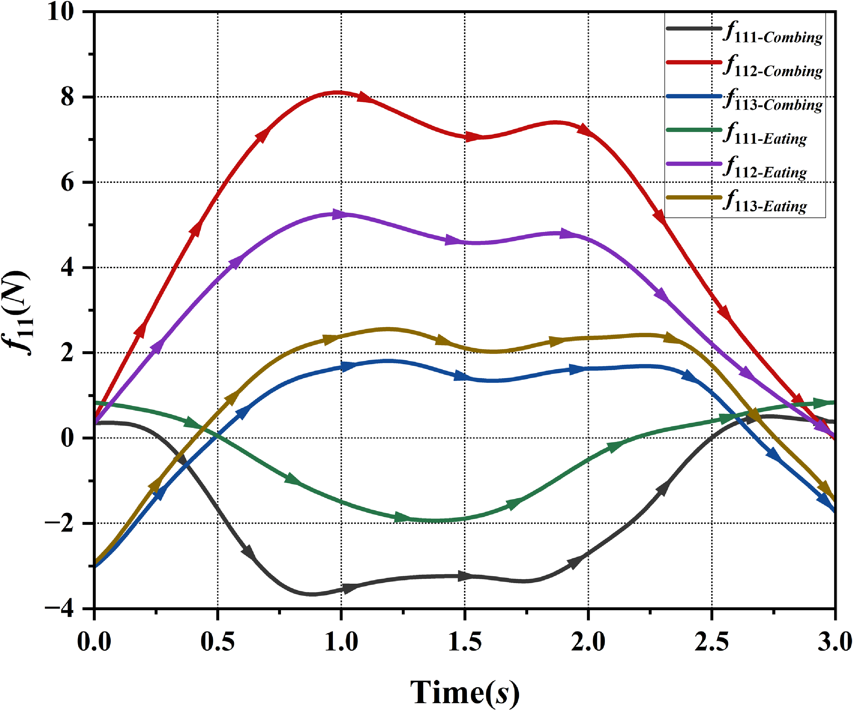
The force exerted on the GH joint in association with the eating and combing movement.

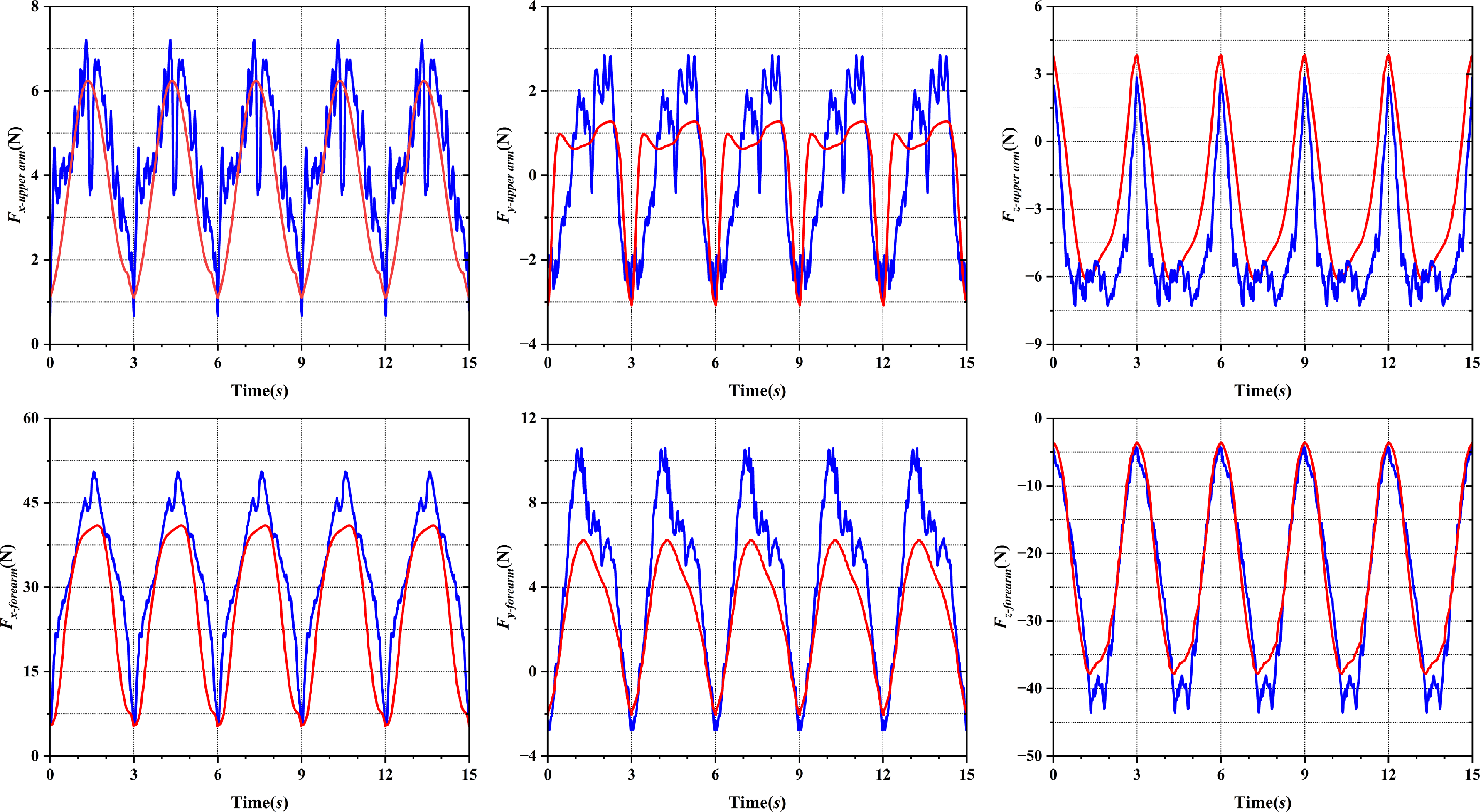
Comparison of simulated and experimental human-robot interaction forces for eating movement trajectory.

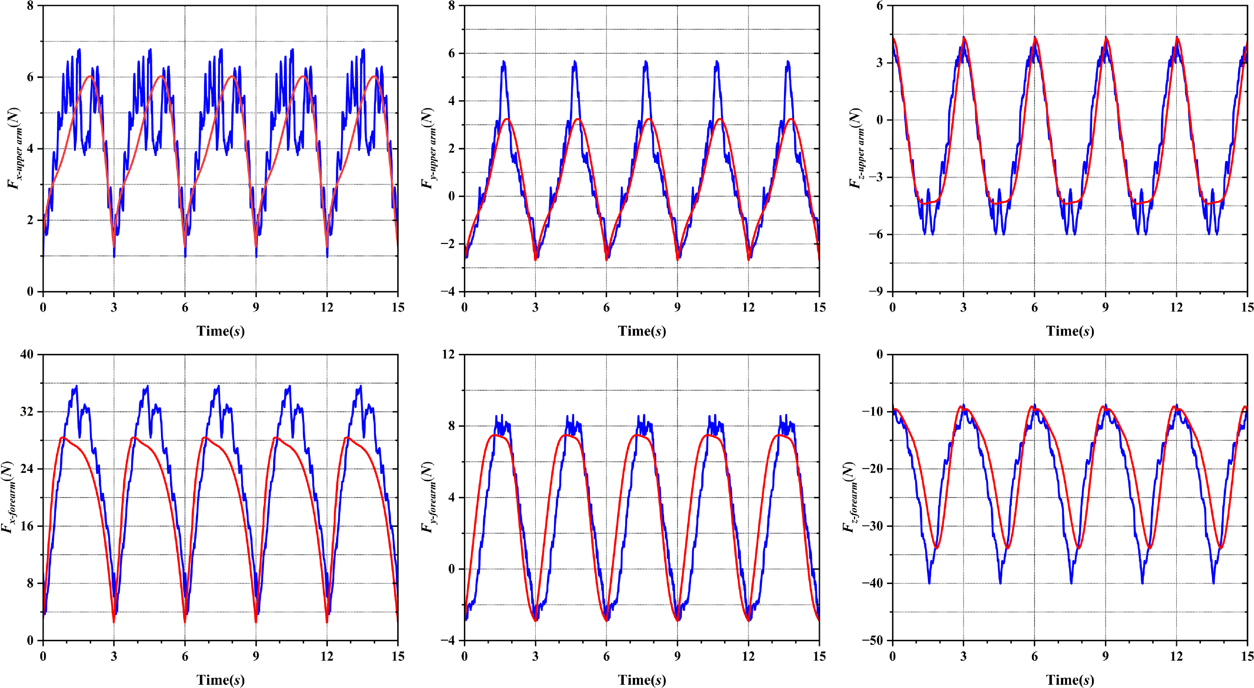
Comparison of simulated and experimental human-robot interaction forces for combing movement trajectory.

5.1. Simulation and experimental results
In Section 3.2, human-robot interaction forces are measured. The measurement of interaction forces provided a quantification of the general residual, undesired and uncontrolled forces acting between the robot and the users. It was noteworthy that all experiments were performed in the passive mode of the robot; theoretically, the upper limbs should not experience any load at the connection interfaces. According to the experimental steps in chapter 4, we measured the change of the interaction forces when the human-robot closed chain was training for both eating and combing hair movements. Subsequently, the obtained data results are stored and analyzed. When analyzing the data, we removed the movement data of one cycle at the beginning and the end respectively, and selected the middle five cycles with relatively stable data to plot the curve. After that, the average norm of the measurement data of all volunteers was addressed, and the interaction forces were plotted, and the experimental results (ER) were shown in Figures 10 and 11 (blue line).
By observing Figure 9, an interesting phenomenon can be noted: when the human-robot closed chain performed both the eating and combing movements, the GH joint experienced internal restraint forces in all three directions. Specifically, the internal forces along the X-axis and Y-axis of the kinematic coordinate system were superimposed with the effective forces required for rehabilitation training, facilitating the flexion/extension and adduction/abduction movements of the upper arm. As illustrated in Figure 9, the internal forces for both the eating and combing movements varied over time, with different force components (f111, f112, f113) exhibiting distinct patterns. During the eating movement, the internal force (f111) along the Z-axis reached a maximum value of 1.98N, while during the combing movement, the same force component peaked at 3.23N. Notably, both values were within the acceptable range, indicating that neither movement posed a risk of causing discomfort or injury to the user. These force measurements are crucial for understanding the distribution and variation of interaction forces under different rehabilitation conditions. Evaluating these internal forces provides valuable insights for optimizing the configuration design of upper extremity rehabilitation robots to ensure safe and effective operation. Additionally, this evaluation helps explain why, in some rehabilitation sessions, doctors assist by holding the patient’s arm synchronously when using certain upper limb rehabilitation robots, thereby minimizing uncontrolled movement. Thus, evaluating the internal forces at the GH joint serves as a key reference for enhancing the design of upper extremity rehabilitation robots.
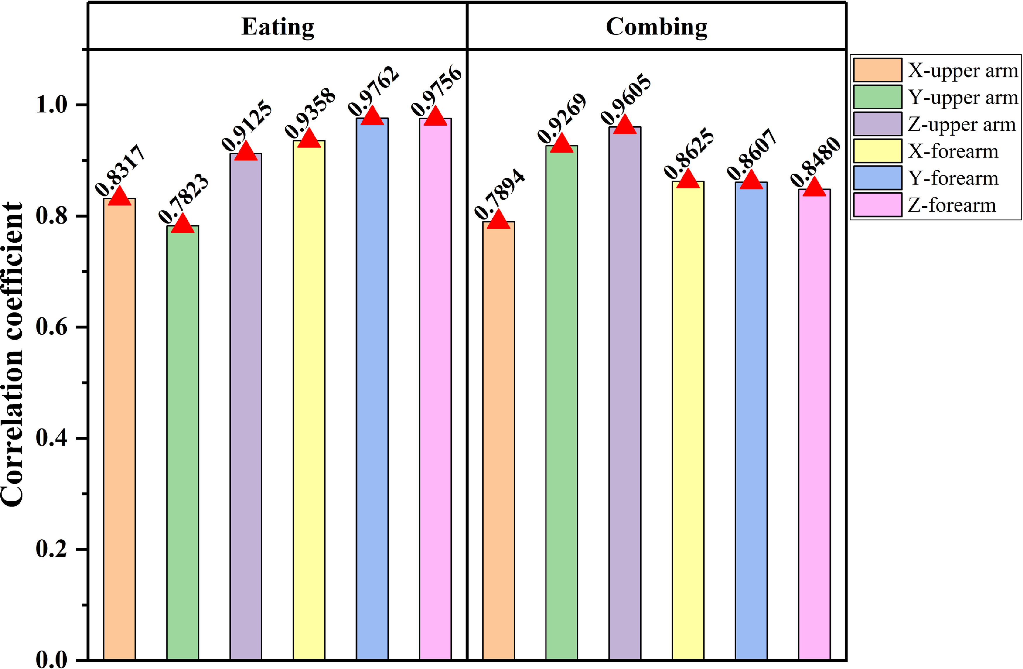
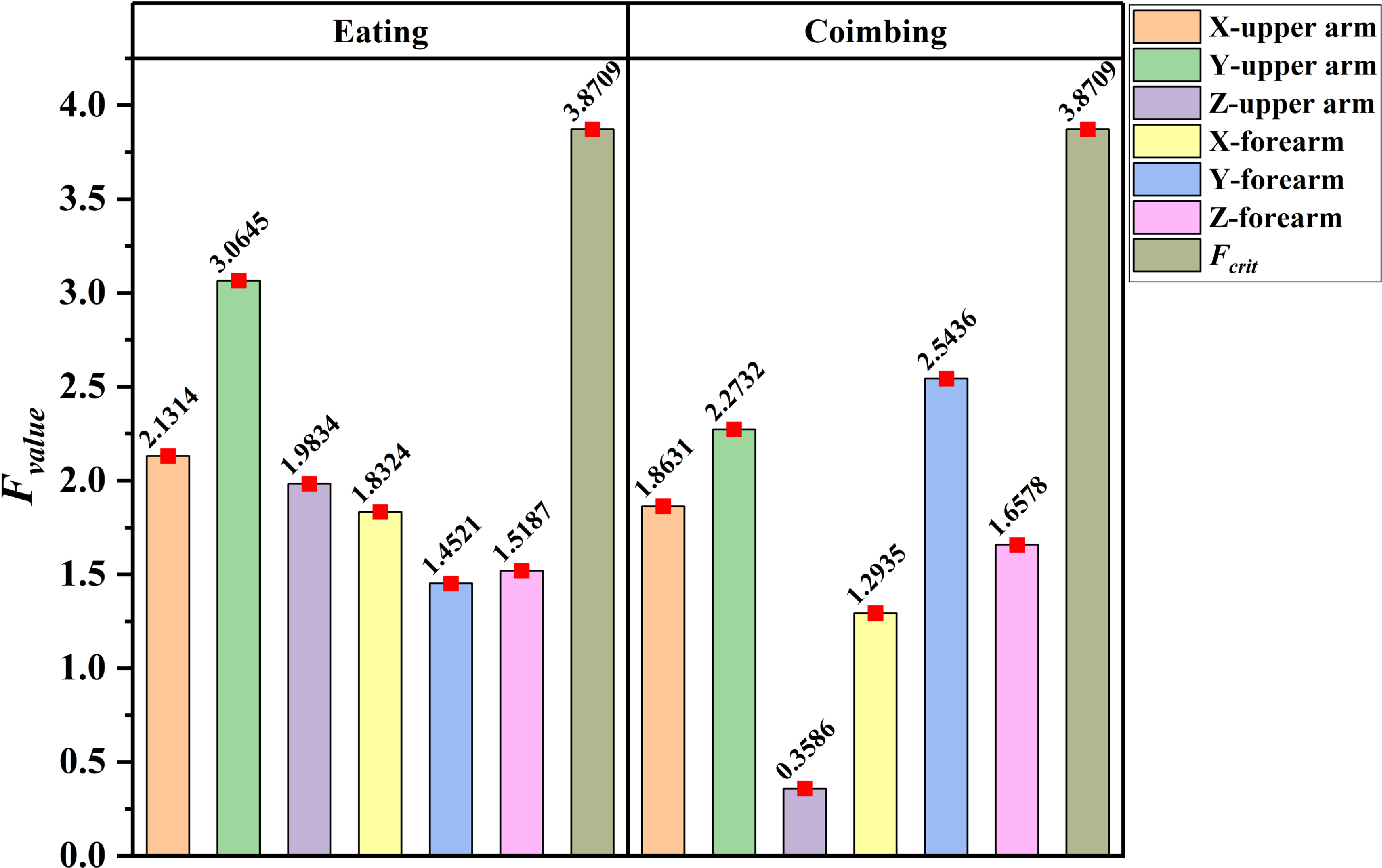
Figures 10 and 11 compare the experimental results (ER) and simulated results (SR) when the closed chain performed the trajectories for both the eating and combing hair movements. Specifically, Figure 10 illustrates the comparison between ER and SR for the eating movement trajectory, while Figure 11 shows the comparison for the combing trajectory. Correlation analysis and one-way analyses of variance (ANOVA) were used to quantitatively assess the variation trends and significant differences between ER and SR. The findings from the correlation analysis are presented in Figure 12, which shows that the minimum Pearson correlation coefficient was 0.79542, indicating a strong correlation between ER and SR. This suggests that the variation trends of ER and SR were highly consistent. In addition to correlation analysis, significant differences between ER and SR were also examined, with the results shown in Figure 13. The conclusions presented in Figure 13 indicated that the F value was less than the F crit value for all ER and SR comparisons, regardless of whether the interaction forces involved the forearm or upper arm. This finding demonstrates that there was no significant difference between ER and SR, suggesting consistency between the two sets of results. Based on the above analysis, it can be concluded that ER and SR exhibit good synchronization, demonstrating that the proposed method for estimating human-robot interaction forces is both effective and feasible.
Correlation coefficient between ER and SR for eating and combing movements.

Significant difference between ER and SR for eating and combing movements.

Figures 10 and 11 provide a comprehensive understanding of the interaction forces and movements during both the eating and combing tasks. Each figure consists of six subplots: the top row depicts the interaction forces in three directions for the upper arm, and the bottom row represents the forces in three directions for the forearm. Specifically, Figure 10 represents the eating movement, while Figure 11 represents the combing movement. The predictable results shown in these figures offer valuable insights into the understanding of interactive forces and movement dynamics.
-
Upper Arm Forces Analysis (Top Row of Figures 10 and 11). It can be seen from Figures 10 and 11 that, regardless of whether they are SR or ER, the trajectory curves of the upper arm interaction forces indicate significant changes in the restraint forces along the Y-axis and Z-axis of the kinematic coordinate system. For the eating movement in Figure 10, the maximum values reached 2.8N and 6.3N for the Y-axis and Z-axis forces, respectively. These forces were effective in achieving the flexion/extension and adduction/abduction movements of the upper arm, contributing positively to the rehabilitation process. However, the maximum value of the force along the X-axis was observed to be 6.8N, which acted as a negative restraint force. Such negative forces could impact the comfort of rehabilitation therapy, emphasizing the importance of minimizing these forces to enhance user comfort. Similarly, for the combing hair movement in Figure 11, the interaction forces along the Y-axis and Z-axis reached maximum values of 3.1N and 4.4N, respectively. These forces effectively facilitated the necessary rehabilitation movements of the upper arm. Conversely, the force along the X-axis reached a maximum of 6.1N, which was also a negative restraint force and could potentially affect the comfort of the rehabilitation session.
-
Forearm Forces Analysis (Bottom Row of Figures 10 and 11). The bottom row of Figures 10 and 11 depicts the interaction forces for the forearm in three directions. During the eating movement (Figure 10), the maximum value of the restraint force along the X-axis of the kinematic coordinate system reached 48.2N. This force contributed effectively to the flexion/extension movement of the forearm, serving as an effective force for rehabilitation. In contrast, the force along the Z-axis was relatively large, with a maximum value of 43.7N, acting as a negative constraint force. Such negative forces could have a passive effect on rehabilitation, potentially hindering the smooth execution of training exercises. The Y-axis force, predominantly influenced by inertial effects, exhibited smaller values and limited variation, indicating a minor negative impact on the rehabilitation process. In the combing movement (Figure 11), similar trends were observed. The X-axis restraint force reached a maximum of 28.9N, contributing effectively to the flexion/extension of the forearm. The Z-axis force peaked at 33.8N, acting as a negative constraint force that could impede rehabilitation. The Y-axis force remained relatively small and was primarily influenced by inertia. However, in the robot configuration investigated, the presence of the passive joint P8 mitigated the negative impact of the Y-axis force by aligning with its direction of movement. As a result, the negative effect of the Y-axis force was effectively canceled, minimizing its impact on the rehabilitation movement of the upper extremity.
The results of this analysis underscore the importance of understanding the relationship between interaction forces and movement in the design of rehabilitation robots. Effective configuration design must consider both the positive and negative interaction forces to optimize safety, comfort, and therapeutic efficacy. Furthermore, these findings emphasize that accurately calculating and evaluating interaction forces is a crucial factor in advancing rehabilitation robotics, providing a foundation for designing systems that enhance patient outcomes through precise control of human-robot interactions.
5.2. Comparison with existing systems
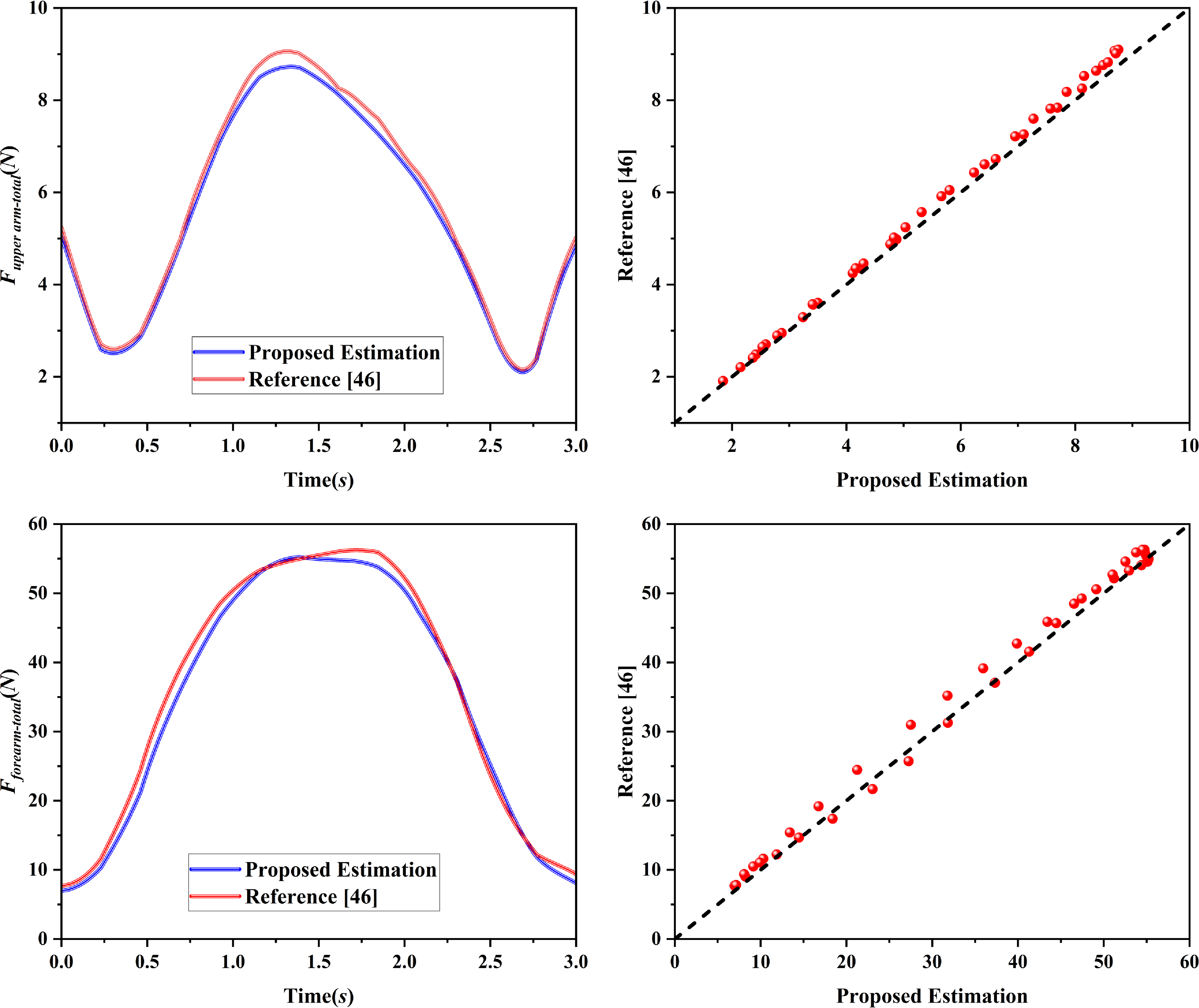
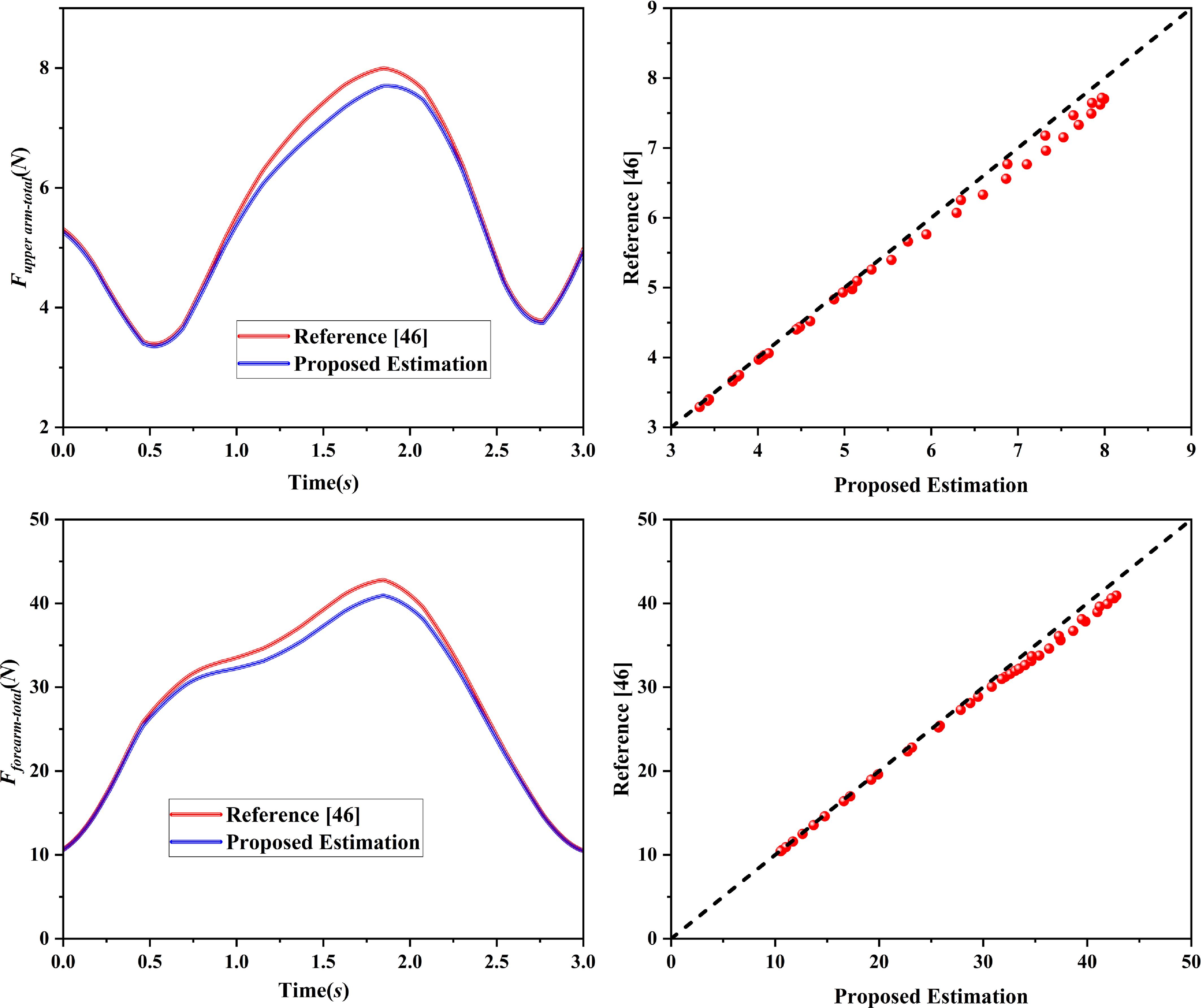
To compare the proposed method with existing systems, we refer to a recent study that presents an adaptive approach for estimating human-robot interaction forces in lower-limb rehabilitation robots [Reference Liang, Wang and Hou27]. The method proposed in this study models the dynamics of the human-robot system, establishes a state-space equation, and describes the interaction force as a polynomial function of time. A Kalman filter is employed to estimate the extended state of the system online, while an adaptive Kalman filter is used to correct the covariance matrices of system noises. The method was validated experimentally on a lower-limb rehabilitation robot, showing good accuracy and real-time performance in estimating interaction forces. Although this approach was originally designed for lower-limb rehabilitation robots, its fundamental principles and techniques are highly adaptable to upper-limb rehabilitation systems. The underlying dynamics of human-robot interaction in both contexts share similarities, particularly regarding the interaction forces that arise during rehabilitation movements. Therefore, it is feasible to apply this methodology to estimate the interaction forces for upper-limb rehabilitation robots, making it a valuable reference for this study. Figure 14 presents the comparison of the estimated interaction forces during the eating movement, using both the reference method and the proposed method. The red curve in Figure 14 represents the interaction forces estimated by the method from Ref. [Reference Wang44], while the blue curve shows the interaction forces estimated using our proposed method. Similarly, Figure 15 presents the comparison for the combing movement, with the same color scheme for ease of reference. These curves represent simulation results, as both methods utilize the same input trajectory data for the upper-limb joints during each movement.
Comparison of human-robot interaction forces during eating movement: proposed vs. reference method.

Comparison of human-robot interaction forces during combing movement: proposed vs. reference method.

The comparison of human-robot interaction forces, as estimated by both our proposed method and the reference method Ref. [Reference Wang44], is shown in Figures 14 and 15 for the eating and combing movements, respectively. Both figures illustrate the estimated interaction forces for the upper arm and forearm, with distinct trends and key observations that are worth noting.
Eating Movement (Figure 14): In Figure 14, the interaction forces for both the upper arm and forearm show clear patterns of change. For the upper arm, the interaction force initially decreases and then increases over the course of the movement. This reduction at the beginning could be attributed to the robot adjusting its position in response to the human’s initial movement, followed by an increase as the robot applies more force to assist with the rehabilitation task. In contrast, the forearm interaction force shows an initial increase, followed by a decrease. This behavior reflects the initial engagement of the forearm in the movement, with forces growing as the motion starts and then tapering off as the rehabilitation task progresses. When comparing the peak values, it is evident that the reference method (red curve) predicts higher forces than our method (blue curve). Specifically, the peaks for the reference method are more pronounced. This discrepancy can likely be explained by the fact that the reference method utilizes a polynomial-based force description that may not account for certain damping or compliance effects in the system as accurately as our proposed approach. The reference method, which also employs a Kalman filter for state estimation, might overestimate forces in some regions of the motion, particularly in moments of rapid change. The higher peak values could be a result of the filtering process, which aims to smooth system states, but might inadvertently amplify short-term fluctuations in force. Despite the differences in peak force values, the error analysis shows that the relative errors between the two methods are quite small, generally remaining below 0.05. The error curve (shown in the figure) indicates that the two methods align closely in terms of overall force trends, with only minor discrepancies in peak force predictions. This suggests that while the reference method might overestimate the peak forces, the overall force profile—both in terms of trends and general magnitude—remains very consistent across both methods.
Combing Movement (Figure 15): The trends in Figure 15, for the combing movement, mirror those observed in Figure 14 for the eating movement. In this case, both the upper arm and forearm interaction forces again follow the same general trends, with the upper arm forces showing a decrease followed by an increase, and the forearm forces initially rising before decreasing. These patterns are consistent with the dynamic requirements of the combing movement, where the upper limb must accommodate varying levels of force throughout the motion. As in Figure 14, the reference method (red curve) predicts higher peak forces compared to our method (blue curve). This suggests that the same overestimation of peak forces by the reference method occurs in both movements. The reason behind the larger peak values in the reference method could be attributed to its reliance on a polynomial function to describe the interaction force over time. While polynomial functions provide a smooth approximation, they may not accurately reflect the physical damping or passive forces inherent in human-robot interaction. As a result, the reference method might show exaggerated peaks during high-velocity movements, which could be unrealistic in the context of actual rehabilitation training. Once again, the relative errors between the two methods remain small, with most deviations staying well below 0.05. The error curve analysis demonstrates that the two methods are highly consistent in their overall trend estimation, with only slight differences in the magnitude of the forces at certain points. This further supports the feasibility of our proposed method as a reliable and accurate tool for estimating interaction forces in rehabilitation robots.
In summary, while both the reference method [Reference Wang44] and our proposed method exhibit similar trends in estimating the human-robot interaction forces, there are some important distinctions. Our method tends to produce more moderate peak values, reflecting a more accurate modeling of the system’s damping and compliance characteristics. The higher peak forces observed in the reference method can likely be attributed to its use of polynomial-based force description and Kalman filtering, which may not fully capture the dynamic effects in human-robot interaction. Despite these differences, both methods demonstrate high synchronization, with minimal deviations in the force estimation, making our method a feasible and effective alternative for accurately assessing human-robot interaction forces in upper-limb rehabilitation applications.
6. Conclusion and future work
In our work, a 4-DOFs rehabilitation robot configuration with kinematics compatible with upper extremities was proposed. Based on this configuration, an estimation approach for the human-robot interaction forces was presented by using Newton-Euler dynamic equations. For the purpose of verifying the feasibility of the method, a prototype was designed for the proposed robot configuration. Moreover, numerous comparative experiments were performed on the apparatus, and the reliability of the proposed human-robot interaction forces estimation method was evaluated. The investigation outcomes were described below: (1) The undesired loads directly borne by the GH joint were quantified, providing valuable insights for optimizing upper limb rehabilitation robot configurations. (2) A comparative analysis between our method and the force estimation approach from Ref. [Reference Liang, Wang and Hou27], originally developed for lower limb rehabilitation robots, demonstrated good synchronization between the two methods. The results showed that the peak interaction forces predicted by Ref. [Reference Liang, Wang and Hou27] were higher, likely due to differences in dynamic modeling and noise adaptation strategies. Both experimental and simulation results consistently indicated minimal deviation, with relative errors below 0.05, validating the robustness and applicability of our method for upper limb rehabilitation. (3) The relationship between human-robot interaction forces and movement was quantified, which is crucial for improving rehabilitation robot design and enhancing user comfort. This estimation also provides the necessary foundation for evaluating the comfort performance of the robot. Future work will focus on further refining comfort performance evaluation metrics, establishing a rigid-flexible coupling model for human-robot interaction, integrating active and passive control strategies, and improving load calculation methods.
Author contributions
All authors contributed significantly to the development of this manuscript. Qiang Cao conceptualized and designed the study, led the design and development of the robotic system, and drafted the manuscript. Lei Li conducted the experiments, performed data analysis, and contributed to the interpretation of results. Jianfeng Li was involved in the theoretical modeling and the development of the Newton-Euler dynamic equations, and provided technical support throughout the research process. Rui Li assisted in data processing and analysis, and contributed to manuscript revisions. Xun Wang was involved in the design and validation of the robot’s mechanical structure and contributed to revisions of the manuscript. All authors reviewed and approved the final manuscript.
Financial support
This work was supported in part by the “Sponsored by Shanghai Sailing Program, grant No.23YF1414000, in part by Beijing Natural Science Foundation under grant No.3204036, in part by the National Key R&D Program of China under Grant No.2018YFB1307004 and 2020YFC2004200, and in part by the Natural Science Foundation of Beijing Education Committee under Grant No.KM202010005021.
Conflicts of interest
The authors declare that there is no conflict of interest regarding the publication of this paper.