Introduction
In recent years, because of the novel physical and chemical properties, metal molybdate materials have extensive potential applications in many fields such as photoelectronic properties [Reference Zang, Lan, Yang, Wang, Shao, Xu and Su1], humidity sensors [Reference Jeseentharani, Dayalan and Nagaraja2], photocatalysis [Reference Jin, Lu, Ma and Gan3], supercapacitors [Reference Watcharatharapong, Minakshi Sundaram, Chakraborty, Li, Shafiullah, Aughterson and Ahuja4], and lithium ion batteries [Reference Wang, Zhang, Li, Zhang, Xie, Qin, Su and Lan5]. Among them, supercapacitors are widely used in electric vehicles, mobile electronic devices, and high-power electronic products because of their high power density, ultrafast charge and discharge, and good cycle life [Reference Xu, Lin, Wu, Huang, Fan, Xu and Song6, Reference Silva, Noremberg, Marins, Milne, Zhitomirsky and Carreño7, Reference Neeraj, Mordina, Srivastava, Mukhopadhyay and Prasad8]. In pseudocapacitor electrode materials, many transition metal oxides, especially binary metallic oxides, such as NiCo2O4 [Reference Wang and Cui9], CoMoO4 [Reference Altarawneh, Rawadieh, Batiha, Al-Makhadmeh, Al-Shaweesh and Altarawneh10], and MnMoO4 [Reference Wei, Yang, Zhang, Qian and Geng11], are expected to be the ideal electrode materials for supercapacitors because of their higher oxidation state, larger conductivity, and wider electrochemical window range [Reference Qing, Yang, Chen, Li, Wang and Tang12]. Among these bimetal oxide electrode materials, NiMoO4 electrode materials have great potential applications in supercapacitors, because the central ions of transition metals have various valence states and can conduct various reversible redox reactions. The variable valence state of the metal enhances the conductivity of the transition metal oxide in the process of charge and discharge, thus improving its electrochemical properties [Reference Wang, Li, Wu, Liu and Tian13]. Because of the low cost, environmental friendliness, high conductivity of Mo element, and high electrochemical activity of Ni ion, NiMoO4 material has become an ideal electrode material for supercapacitors [Reference Cao, Bu, Lv, Jiang, Wang, Dai, Wang and Shen14, Reference Cai, Liu, Wang, Liu, Wang, Li, Wang, Wang, Li and Wang15, Reference Chen, Yan, Luo, Gao, Huang, Han, Zeng and Zhu16, Reference Li, Jian, Fan, Wang, Yu, Cheng, Zhou and Sun17]. However, after repeated redox reactions, the structure of NiMoO4 material tends to collapse, resulting in poor stability and cycling performance [Reference Huang, Cui, Zhao, Lian, Bao and Li18]. Therefore, a variety of strategies should be adopted, including adjusting and optimizing the morphology, composition, and structure of NiMoO4 material to improve its cyclic stability and specific capacitance [Reference Nti, Anang and Han19].
Generally, the traditional coating electrode process requires the addition of conductive agent (conductive carbon black), binder polyvinylidene fluoride (PVDF), and appropriate amount of solvent (N-methyl pyrrolidone, NMP) [Reference Ezeigwe, Khiew, Siong, Kong and Tan20]. The disadvantage of this process is that the addition of PVDF will hinder the transmission path of electrons, resulting in the decrease of the conductivity of the electrode material. Most of the electroactive surface of the electrode material is also blocked from contacting the electrolyte. In addition, uneven coating will also occur, resulting in dead area of redox reaction [Reference Cai, Liu, Wang, Liu, Wang, Li, Wang, Wang, Li and Wang21]. Finally, the addition of conductive carbon black will also reduce the compaction density of the electrodes, thus reducing the volume energy density of the capacitor. For example, Wei et al. [Reference Wei, Huang, Yan, Chen and Zhang22] successfully synthesized NiMoO4 electrode materials by hydrothermal method. The samples were evenly mixed with acetylene black and PVDF, and then several drops of NMP were added to prepare the working electrode materials. Under the current density of 1 A/g, the discharge specific capacitance of NiMoO4 electrode material is 130.8 F/g. Cai et al. [Reference Cai, Wang, Liu, Wang, Liu, Wang, Li, Huang, Li and Wang23] synthesized NiMoO4 nanospheres by hydrothermal method. The working electrode was prepared by coating process. When the current density is 1, 2, 4, 6, and 10 A/g, the discharge specific capacitance is 974.4, 920.8, 875.5, 859.1, and 821.4 F/g, respectively.
To solve these problems of coating electrode, three-dimensional porous structure of foam nickel can be used as the conductive substrate for the oriented growth of electroactive materials. In this way, NiMoO4 active materials can be directly grown on the foam nickel substrate, so as to prepare an integrated electrode without binders [Reference Ji, Zhang, Ji, Li, Zhao, Bai, Fan, Zhang and Ruoff24, Reference Adhikary, Priyadarsini, Rath and Das25]. Therefore, it is very important to develop a new integrated electrode preparation method. By controlling the morphology, composition, and structure of the electrode materials, and synergizing the advantages of each other, it is possible to prepare supercapacitor electrode materials with large specific capacitance, high power density, and long cycle life.
Solvothermal method is similar to hydrothermal method, but the solvents used in solvothermal method are generally organic solvents, such as ethanol and ethylene glycol [Reference Hammond, Edler, Bowron and Torrente-Murciano26, Reference Quan, Yu, Chung, Jin, Park, Sung and Piao27]. Compared with water, ethanol has lower boiling point, viscosity, and surface tension, and the prepared material has high purity, good crystal shape, and controllable morphology. In this article, we successfully synthesized NiMoO4-integrated electrode materials (binder free) on three-dimensional nickel foam substrate using solvent thermal method with water and ethanol as solvents, and focused on the influence of solvent composition on the properties of target samples.
Results and discussion
Determination of the optimum volume ratio of water to ethanol (W/E)
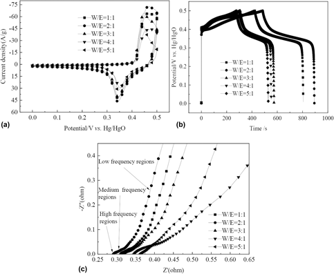
To investigate the electrochemical performance of NiMoO4-integrated materials, cyclic voltammetry (CV), galvanostatic charge–discharge (GCD), and electrochemical impedance spectroscopy (EIS) experiments were conducted with a three-electrode system in 3 M KOH electrolyte solution. Figure 1(a) shows a comparison of the CV curves of NiMoO4 materials prepared in various W/E ratios at a scan rate of 5 mV/s. A couple of strong redox peaks can be clearly observed in all samples with the potential window of 0–0.5 V versus Hg/HgO, suggesting that they are all pseudocapacitive materials [Reference Nti, Anang and Han19]. The pair of redox peaks can be attributed to the Faradic redox process of Ni2+/Ni3+ [Reference Gao, Wu, Wang, Hao and Ge28], and probably associating with anion OH−. Among them, Mo element does not participate in redox reaction, but as a conductor (conductive role), it is beneficial to improving the conductivity of molybdate [Reference Qing, Yang, Chen, Li, Wang and Tang12], thereby increasing the capacitance of supercapacitors. In addition, compared with the CV curves of other samples, the CV curves of NiMoO4-integrated material prepared at the W/E ratio of 2:1 exhibited larger enclosed area and showed a higher peak current. This suggests that the synthesized NiMoO4-integrated electrode has the best charge storage capacity when the W/E ratio is 2:1.
(a) CV curves of NiMoO4 materials prepared in various W/E ratios at a scan rate of 5 mV/s; (b) GCD curves of NiMoO4 materials prepared in various W/E ratios at current density of 1 A/g; (c) EIS plots of NiMoO4 materials prepared in various W/E ratios with the frequency range of 0.1–100,000 Hz.

The capacitive performance was also evaluated by GCD measurement in 3.0 M NaOH aqueous electrolyte with a potential window of 0–0.5 V versus Hg/HgO at a current density of 1 A/g [Fig. 1(b)]. The GCD curves of all samples show the obvious charge–discharge platform owing to obvious redox reaction, confirming the Faraday redox reaction in the cycling process, which is in good agreement with the CV curves. According to these GCD curves, when the W/E ratio is 1:1, 2:1, 3:1, 4:1, 5:1, the discharge times of the prepared NiMoO4 materials are 806, 894, 574, 551, 529 s, respectively. Under the same current density, when w is 2:1, the charge and discharge times of the prepared NiMoO4 electrode are much longer than that under other conditions, indicating that the prepared electrode under this condition has a higher specific capacitance, and the optimal W/E value is 2:1. On the basis of GCD curves and Eq. (1), when the W/E ratio is 1:1, 2:1, 3:1, 4:1, and 5:1, the calculated capacitance of the prepared NiMoO4 electrodes is 764, 815, 535, 505, and 503 F/g, respectively. In addition, there is no obvious IR drop in the GCD curve, confirming the material has an ideal electrochemical behavior [Reference Xu, Lin, Wu, Huang, Fan, Xu and Song6].
The EIS was used to further examine the electrochemical behaviors of the NiMoO4-integrated materials prepared in various W/E ratios, which were tested in the frequency range from 0.1 to 100,000 Hz with an applied potential amplitude of 5 mV, and the results are shown in Fig. 1(c). Each curve of the impedance spectrum has a similar shape, including a single semicircle in the high-frequency region followed by a linear portion in the low-frequency region. Generally speaking, the equivalent series resistance (ESR), a comprehensive outcome from ionic resistance of the electrolyte, inherent resistances of the active material, and contact resistance at the interface of active material and current collector, is indicated by the x-intercept in high-frequency region [Reference Chen, Wang, Luo, Gao, Huang, Zeng and Zhu29]. Apparently, when the W/E ratio is 1:1, 2:1, 3:1, 4:1, and 5:1, the ESR values of the prepared NiMoO4 electrodes are 0.307, 0.287, 0.311, 0.336, and 0.357 Ω, respectively. When the W/E ratio is 2:1, the prepared sample displays the smallest ESR, indicating that this electrode possesses the highest conductivity, suggesting improved charge transport in the electrode. The charge transfer resistance (R ct) is mainly caused by Faraday reaction and double-layer capacitance (C dl) on the surface of grains, which is represented by the semicircle diameter in the high-frequency region [Reference Cai, Liu, Wang, Liu, Wang, Li, Wang, Wang, Li and Wang21]. The Warburg impedance (R W), which presents the ion diffusion–migration at the electrolyte–electrode interface, is indicated by the slope in low-frequency region, illustrating the pseudocapacitive property of the material [Reference Neeraj, Mordina, Srivastava, Mukhopadhyay and Prasad8]. Moreover, the NiMoO4-integrated material prepared at the W/E ratio of 2:1 has a more ideal vertical line in the low frequency range, again validating its lower diffusion resistance [Reference Hong, Wang, Gong, Sun, Niu, Yang, Wang and Yang30]. Obviously, the EIS results confirm the CV and GCD results, that is, the excellent electrical conductivity and minimum diffusive resistance of the material prepared at the W/E ratio of 2:1 are based on fast surface redox reaction (pseudocapacitance) [Reference Senthilkumar and Kalai Selvan31].
Characterization of the optimum ratio sample
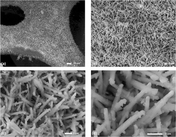
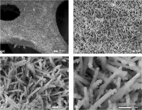
To investigate the morphology of the NiMoO4 materials prepared with a W/E ratio of 2:1, scanning electron microscope (SEM) is performed, as shown in Fig. 2. The low magnification SEM images [Figs. 2(a) and 2(b)] indicate the full coverage of nickel foam with NiMoO4 micro–nanostructures, and after NiMoO4 grows, the surface of the nickel foam becomes rough. From the high magnification SEM images [Fig. 2(c)], it can be seen that the NiMoO4 nanorods have rather uniform diameters and relatively large aspect ratio of length/diameter with locally random growing orientations. Figure 2(d) shows the synthesized NiMoO4 materials were distribution of 1D nanorods with a diameter of 100–200 nm and a length of 2–4 μm. These micro–nanostructures not only have a strong adhesion and electrical contact with nickel foam but also connect to each other and eventually form a network-like structure. In addition, the larger aspect ratio of length/diameter could offer better electrochemical performance [Reference Cai, Liu, Wang, Liu, Wang, Li, Wang, Wang, Li and Wang21]. It is likely that the larger the transverse size of interconnected micro–nanostructures, the more abundant space and electroactive sites for the redox process are generated, especially at high current densities, which indicates the surprising energy advantages of one-dimensional nanostructures [Reference Chen, Liu, Liu, Wang, Liu, Zhang, Hu and Jing32].
(a–d) Typical SEM images of NiMoO4 nanorods prepared with a W/E ratio of 2:1 at different magnifications.

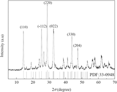
The crystal structure and crystalline phase of the as-synthesized NiMoO4 nanorods were confirmed by powder X-ray diffraction (XRD) analysis, and the intensity versus 2θ plot has been presented in Fig. 3. Obviously, six main diffraction peaks were observed at 14.3°, 25.3°, 28.8°, 32.6°, 43.9°, and 47.4°, which can be unambiguously indexed to the (110),  $\left( {\bar{1}12} \right)$, (220), (022), (330), and (110) diffraction planes of monoclinic structured α-NiMoO4 (JCPDS 33-0948) with a space group of C 2/m, which is consistent with the previous reports [Reference Lin, Liu, Liu, Sun, Hao, Ji and Wang33]. Other impurity peaks, such as NiO and MoO3, were not found in the XRD pattern, which confirmed the successful synthesis of NiMoO4 nanorods. Furthermore, the weak intensities of diffraction peaks indicate the poor crystallinity, which may be beneficial to present an excellent capacitive behavior, because the poor crystallinity is favorable for electrons transfer [Reference Nti, Anang and Han19].
XRD pattern of NiMoO4 nanorods prepared with a W/E ratio of 2:1.

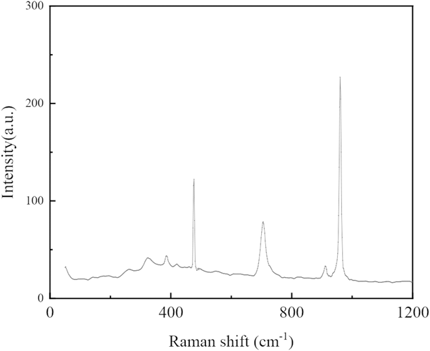
To investigate the surface functional groups of the NiMoO4 nanorods, Raman spectra measurements were taken. As shown in Fig. 4, the Raman spectrum shows some intense and weak peaks. The three distinct intense peaks located at 960, 911, and 705 cm−1, which can all be attributed to the symmetric and asymmetric stretching modes of the Mo–O bonds. In addition, some other weak peaks at 475, 383, and 323 cm−1 are usually assigned to the bending mode of Mo–O, and the band at 261 cm−1 has been attributed to the deformation mode of Mo–O–Mo, respectively [Reference Abdel-Dayem34]. The spectrum is in well consistent with previous reports of stoichiometric α-NiMoO4 [Reference Fan, Li, Zhao, Wei, Liu, Duan and Jiang35, Reference Jothi, Shanthi, Salunkhe, Pramanik, Malgras, Alshehri and Yamauchi36], further proving that the synthesis of NiMoO4 is successful.
Raman spectra of NiMoO4 nanorods prepared with a W/E ratio of 2:1.

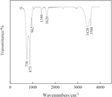
The structure of the as-synthesized NiMoO4 nanorods can be further confirmed by FT‐IR experiment. As can be seen from Fig. 5, the low frequency absorption peak at 738 cm−1 can be assigned to the Mo–O deformation vibration [Reference Hu, Yu, Jiang, Liu, Jin, Lu, Zhao, Wu and He37]. The significantly strong absorption bands at 873 cm−1 are assigned to the stretching vibrations of Mo–O–Mo [Reference Seevakan, Manikandan, Devendran, Shameem and Alagesan38]. In this case, a peak at 962 cm−1 is due to the stretching of Mo–O linkage. The band at 1380 cm−1 can be ascribed to the C–O stretching vibration [Reference Senthilkumar, Vijaya Sankar, Kalai Selvan, Danielle and Manickam39]. Moreover, three absorption peaks observed at 1620, 3428, and 3588 cm−1 can be attributed to the O–H stretching vibrations of the water molecules adsorbed on the surface of NiMoO4 [Reference Kazemi, Bahmani, Kazemi and Kiani40]. The results further confirmed the formation of metal oxide (M-O) bands and the existence of nickel and MoO4, which are in good agreement with the obtained XRD and Raman spectroscopy results.
FT-IR spectra of NiMoO4 nanorods prepared with a W/E ratio of 2:1.

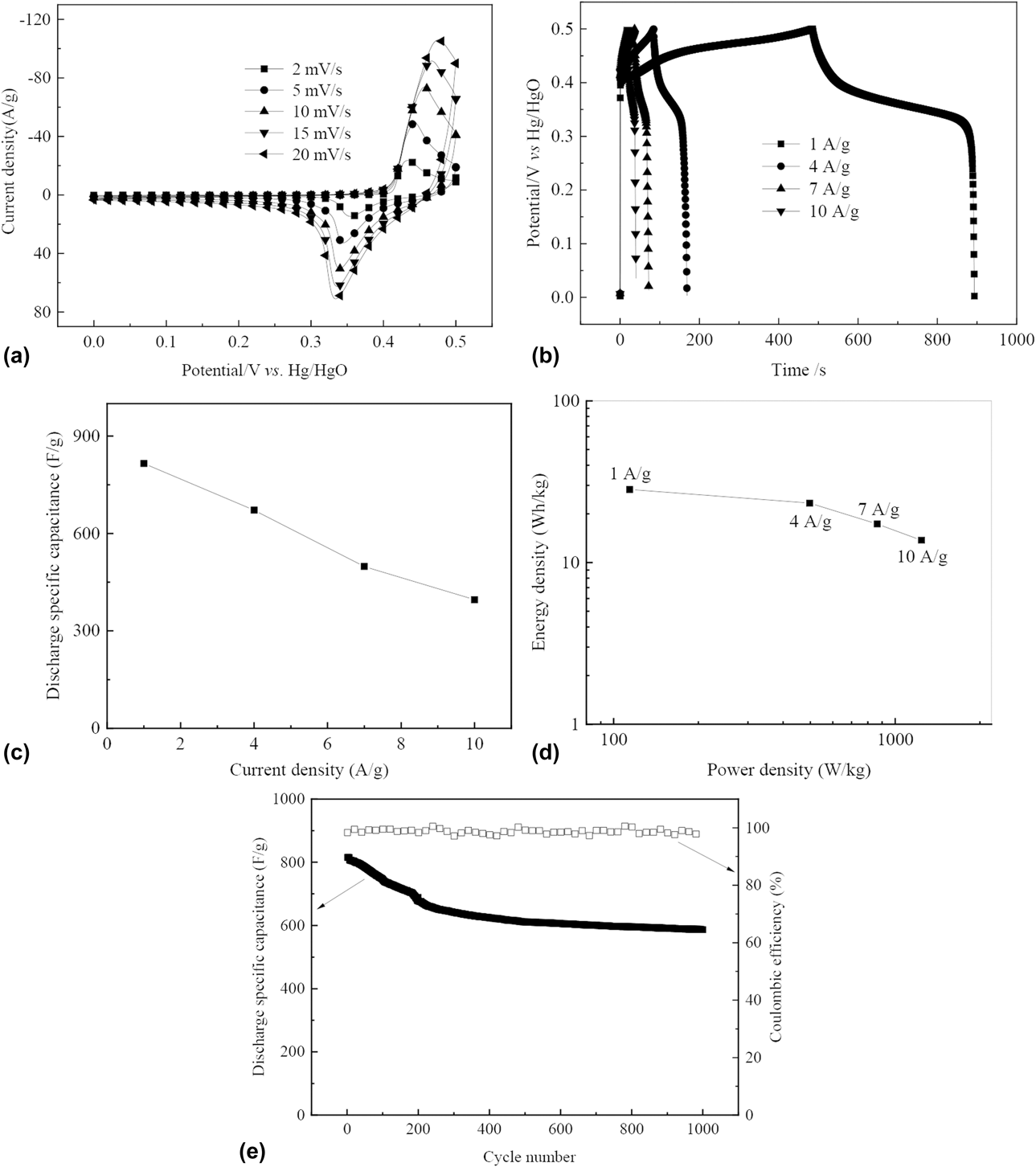
To investigate the electrochemical properties of NiMoO4 nanorods electrode prepared with a W/E ratio of 2:1, a series of electrochemical investigations, that is, CV and GCD were conducted in a three-electrode configuration containing 3 mol/L KOH aqueous solution as the electrolyte. Figure 6(a) shows the typical CV curves of NiMoO4 nanorods electrode recorded in a potential window of 0–0.5 V at various scan rates of 2, 5, 10, 15 and 20 mV/s, respectively. It can clearly observe that the CV curve consisted of two strong redox peaks, indicating the redox reactions and pseudocapacitive characteristic of the material. The obvious oxidation and reduction peaks potentials are located at 0.43–0.47 V and 0.33–0.36 V, which could be attributed to the reversible electron transfer process of the Ni2+/Ni3+ redox couple [Reference Dong, Li, Wang and Yang41]. Mo, though a transition metal, does not directly partake in redox reactions, and its main function is to improve the conductivity of the electrodes [Reference Nti, Anang and Han19]. Furthermore, as the scan rate increases from 2 to 20 mV/s, the cathodic and anodic peaks shift to the opposite directions, the peak current increases, and the shape of the CV curves maintains well at all scan rates, suggesting that the polarization and quasireversible feature of the electrode [Reference Seevakan, Manikandan, Devendran, Shameem and Alagesan38]. This indicates the superior rate capability and good reversibility of the material.
(a) CV curves of NiMoO4 nanorods electrode prepared with a W/E ratio of 2:1 at various scanning rates; (b) GCD curves of NiMoO4 nanorods electrode prepared with a W/E ratio of 2:1 under different current densities; (c) specific capacitances of NiMoO4 nanorods electrode prepared with a W/E ratio of 2:1 at different current densities; (d) Ragone plot of NiMoO4 nanorods electrode prepared with a W/E ratio of 2:1 at different current densities; (e) cyclic performance of NiMoO4 nanorods electrode prepared with a W/E ratio of 2:1 at a constant current density of 1 A/g.

To further assess the capacitive performance of NiMoO4 nanorods electrode, GCD measurements were performed in the potential range from 0 to 0.5 V at a current density of 1, 4, 7, and 10 A/g, respectively. As shown in Fig. 6(b), the GCD curves are obvious nonlinear lines with a distinct voltage plateaus around 0.35 V, further proving the pseudocapacitive nature of the as-prepared electrode materials due to the Faradaic reactions [Reference Zhang, Yin, Liu, Wang and Gu42], which is consistent with the CV results. Furthermore, the discharge time decreases with the increase of current density, which leads to the decrease of specific capacity. This could be attributed to the fact that the active materials may be insufficient to participate in redox reactions at higher current densities, thus resulting in only a certain portion of the active material being utilized [Reference Tian, Li, Yang, Wang, Wang, Song, Liu and Guo43].
Figure 6(c) shows the specific capacitance changes of NiMoO4 nanorods electrode with different current densities. First, Eq. (1) is used to calculate specific capacitance from GCD curve. The specific capacitances of the samples were calculated to be 815, 672, 498, and 396 F/g at the current densities of 1, 4, 7, and 10 A/g, respectively. By increasing the current density from 1 to 10 A/g, the specific capacitance decreased about 51%, indicating the better rate capability of the electrode. This good rate capability could be attributed to the one-dimensional nanorods structure, which improves the ion kinetics as well as electron transport at the electrode–electrolyte boundary and the electrodes. In addition, the direct growth of NiMoO4 on the surface of Ni foam ensures good mechanical adhesion and electrical connection to collectors, avoiding the use of polymer adhesives and conductive additives, which usually increase the series resistance and deterioration of capacitance in redox reactions. The positive synergistic effect of nickel and molybdenum ions in the transition metal oxide NiMoO4 can also significantly improve its capacitance characteristics [Reference Seevakan, Manikandan, Devendran, Shameem and Alagesan38].
In view of the good rate performance, the energy density and power density are further calculated, which are two key parameters in the practical application of supercapacitors. Figure 6(d) shows the Ragone plot (energy density versus power density) of NiMoO4 nanorods electrode prepared with a W/E ratio of 2:1 at different current densities. As shown in Fig. 6(d), when the power density is 114 W/kg, the energy density reaches 28.3 W h/kg. Even when the power density is 1241 W/kg, the energy density still reaches 13.8 W h/kg. These excellent electrochemical properties, combined with other advantages in the synthesis process, make NiMoO4 nanorods become a very competitive electrode material for supercapacitors.
As a critical requirement for practical applications, the long-term cycling stability of the synthesized NiMoO4 nanorods electrode materials is extremely important. Figure 6(e) shows the capacitance changes of 1000 charge–discharge cycles at current density of 1 A/g in the 0–0.5 V potential window. As can be seen, after 1000 cycles, the discharge specific capacitance of electrode decreases gradually from 815 to 588 F/g, with only about 28% specific capacitance loss to the initial value, indicating a distinguished electrochemical stability. The enhanced long cycle stability is mainly attributed to its unique nanorods structure, which provides effective contact surface area, more active sites for the electrolyte to effectively diffuse to the whole electrode during long-term cycling test, and improves the charge transfer kinetic of ions and electrons. The slight decrease of capacitance is usually caused by the structural damage, particle agglomeration, instability of material–electrolyte interface and dissolution of some electrode materials during the ion insertion–removal process [Reference Neeraj, Mordina, Srivastava, Mukhopadhyay and Prasad8].
Conclusions
In conclusion, NiMoO4 nanorods on Ni foam have been successfully synthesized by a facile solvothermal method, which has high electrochemical properties for pseudocapacitors. The electrochemical performance can be optimized by the W/E ratios, and the sample shows the optimum capacitance performance with a W/E ratio of 2:1. The 2:1 ratio exhibited pure phase monoclinic crystal NiMoO4 on the surface of Ni foam with the highest specific capacitance of 815 F/g at 1 A/g and outstanding cycling life (72% after 1000 cycles at a current density of 1 A/g), as compared to other tested materials. The particles exhibit nanorods microstructure; its diameter and length are 0.1–0.3 µm and approximately 3 µm, respectively. Because of its unique nanorods structure, effective contact surface area, more active sites for the electrolyte to effectively diffuse to the whole electrode, and positive synergistic effect of nickel and molybdenum ions, resulting in the NiMoO4, delivered a discharge specific capacitance of 672, 498, and 396 F/g at a current density of 4, 7, and 10 A/g, respectively. These results demonstrate that the NiMoO4 nanorods–integrated electrode materials could be a promising electrode material for high-performance supercapacitor and various energy storage devices applications.
Experimental
Material preparation
All chemicals were of analytical grade and used as received without further purification. The nickel foams matrix (Changsha Lyrun New Material Co., Ltd., Changsha, China) was pretreated by degreasing in acetone, etching in HCl for 5 min, then rinsed with deioned water, and dried before use [Reference Wang, Li, Wu, Tian, Liu and Yu44]. First, 1 mmol NiSO4·6H2O, 1 mmol Na2MoO4·2H2O, and 6 mmol urea were dissolved in ethanol–water mixture with various volume ratios (volume ratio of water to ethanol (W/E) was 1:1, 2:1, 3:1, 4:1, and 5:1, respectively), until completely dissolved under magnetic stirring conditions. The pretreated nickel foam is placed in the bottom of the reactor, then the above dissolved solution is transferred to a 100 mL stainless steel autoclave, and the NiMoO4 precursor was obtained at 150 °C for 6 h. Finally, the NiMoO4 precursor was calcined at 400 °C for 2 h, and eventually the NiMoO4 integrated material was directly grown on foamed nickel.
Structure characterizations
The microscopic surface morphologies of the as-synthesized samples were examined by scanning electron microscope (SEM; JSM-6490LU, JEOL, Tokyo, Japan). To identify the phase components and crystal structure, the X-ray diffraction (XRD) experiments were conducted in (Bruker D8 Advance; Bruker Corp, Billerica, MA) X-ray diffractometer using the Cu Kα line. Raman spectra of the materials were recorded by using a Fourier transform Raman spectrometer—Lab RAM (LabRAM system, Dilor, Lille, France) with excitation wavelength and laser power of 532 nm and 50 mW, respectively. Structural investigations were analyzed using TENSOR27 Fourier transform infrared spectroscopy (FT-IR) by Bruker, Germany.
Electrochemical measurements
The electrochemical properties of the prepared NiMoO4 materials were analyzed using cyclic voltammetry (CV), galvanostatic charge–discharge (GCD), and electrochemical impedance spectroscopy (EIS). A CHI 660E electrochemical workstation (Chenhua, Shanghai, China) was used with a three-electrode system containing 3 M KOH solution. For the three-electrode system, the as-prepared integrated NiMoO4 electrode was directly used as working electrode without using any binder or conducting additives. In addition, an Hg/HgO and a Pt electrode were used as reference electrode and auxiliary electrode, respectively. CV was recorded between 0 and 0.5 V versus Hg/HgO at scan rates of 5, 10, 15, 20, and 25 mV/s, respectively. The GCD characteristics of the samples were investigated at various current densities of 1, 4, 7, and 10 A/g between 0 and 0.5 V versus Hg/HgO. The EIS data were collected over a frequency range of 0.1–100,000 Hz under a perturbation amplitude of 5 mV. The specific capacitance (C m, F/g) is calculated from the GCD curves according to the following Eq. (1):
 $${C_{\rm{m}}} = {C \over m} = {{i \times \Delta t} \over {m \times \Delta u}}\quad ,$$
where i (A), m (g), Δt (s), and Δu (V) represent the discharge current, the mass of active electrode material, the total discharge time, and the potential window, respectively.
Acknowledgments
This work is supported by the Program for Science and Technology Innovation Team in Universities of Henan Province (Grant No. 16IRTSTHN016), the National Natural Science Foundation of China (Grant No. 21503193), and the National Natural Science Foundation of China (Grant No. U1404201).