


1. Introduction
The flow between two counter-rotating coaxial circular cylinders known as Taylor–Couette (TC) flow is a paradigm in fluid mechanics for studies of instability, spatiotemporal chaos, pattern formation and turbulence (Grossmann, Lohse & Sun Reference Grossmann, Lohse and Sun2016). On the other hand, due to its simple geometry, and experimental accessibility with high precision, the TC system also becomes an ideal test bed for various drag reduction methods, such as adding drag reducers (Groisman & Steinberg Reference Groisman and Steinberg1996; Nakken, Tande & Elgsaeter Reference Nakken, Tande and Elgsaeter2001; Guersoni et al. Reference Guersoni, Bannwart, Destefani and Sabadini2015; Van Buren & Smits Reference Van Buren and Smits2017), injection of bubbles (Van den Berg et al. Reference Van den Berg, Luther, Lathrop and Lohse2005; Murai, Oiwa & Takeda Reference Murai, Oiwa and Takeda2008; Sugiyama, Calzavarini & Lohse Reference Sugiyama, Calzavarini and Lohse2008; Verschoof et al. Reference Verschoof, Bakhuis, Bullee, Huisman, Sun and Lohse2018), using the Leidenfrost effect (Saranadhi et al. Reference Saranadhi, Chen, Kleingartner, Srinivasan, Cohen and McKinley2016; Ayan, Entezari & Chini Reference Ayan, Entezari and Chini2019) or modification of solid surfaces (Greidanus, Delfos & Westerweel Reference Greidanus, Delfos and Westerweel2011; Srinivasan et al. Reference Srinivasan, Kleingartner, Gilbert, Cohen, Milne and McKinley2015; Rosenberg et al. Reference Rosenberg, Van Buren, Fu and Smits2016; Hu et al. Reference Hu, Wen, Bao, Jia, Song, Song, Pan, Scaraggi, Dini and Xue2017; Naim & Baig Reference Naim and Baig2019). In TC flow, pairs of counter-rotating vortices arise when the Reynolds number ( $Re$) exceeds a critical value (Andereck, Liu & Swinney Reference Andereck, Liu and Swinney1986; Maretzke, Hof & Avila Reference Maretzke, Hof and Avila2014; Grossmann et al. Reference Grossmann, Lohse and Sun2016). Nominally for moderate
 $Re$ (
 $10^3$–
 $10^4$) and
 $0.5<\eta <0.75$, the aspect ratio (
 $\Gamma = l/d$) of the vortices is close to unity (Chouippe et al. Reference Chouippe, Climent, Legendre and Gabillet2014; Burkhalter & Koschmieder Reference Burkhalter and Koschmieder1973, Reference Burkhalter and Koschmieder1974); here
 $l$ is the axial length of the vortex,
 $d$ is the gap width between the two cylinders and
 $\eta$ is the radius ratio, which is defined in § 2. When the flow reaches the steady state, the number of vortices allowed in a fluid annulus of height
 $h$ is roughly
 $n=h/d$. It has been shown previously that for the same
 $h$, flow states with different number of vortices are possible (Benjamin & Mullin Reference Benjamin and Mullin1981, Reference Benjamin and Mullin1982; Cliffe & Mullin Reference Cliffe and Mullin1985; Pfister et al. Reference Pfister, Schmidt, Cliffe and Mullin1988). Similar phenomena also occur in circular Couette flow with pressure-driven axial flow (Takeuchi & Jankowski Reference Takeuchi and Jankowski1981; Chung & Astill Reference Chung and Astill1977; Lueptow, Docter & Min Reference Lueptow, Docter and Min1992) or when fluid is added or withdrawn through a permeable inner cylinder (Min & Lueptow Reference Min and Lueptow1994; Tilton & Martinand Reference Tilton and Martinand2018). It is found that for flow states with fewer than the nominal number of vortices, these vortices are highly stretched in the axial direction and occupy the whole liquid annulus height
 $h$ (Benjamin Reference Benjamin1978a,Reference Benjaminb; Martínez-Arias et al. Reference Martínez-Arias, Peixinho, Crumeyrolle and Mutabazi2014; Mansour, Ali & El-Maksoud Reference Mansour, Ali and El-Maksoud2016; Ostilla-Mónico, Lohse & Verzicco Reference Ostilla-Mónico, Lohse and Verzicco2016). These multiple flow states have recently been found to exist even at extremely high Reynolds number (
 ${\sim }10^6$) in turbulent TC flows (Huisman et al. Reference Huisman, Van Der Veen, Sun and Lohse2014), where only one flow state is expected. The reported methods for generating different flow states include continuously adjusting the liquid annulus height using a sliding top plate between the inner and outer cylinders while the inner cylinder keeps rotating (Benjamin Reference Benjamin1978b; Mansour et al. Reference Mansour, Ali and El-Maksoud2016) or adjusting the starting acceleration rate of the inner cylinder (Xiao, Lim & Chew Reference Xiao, Lim and Chew2002; Martínez-Arias et al. Reference Martínez-Arias, Peixinho, Crumeyrolle and Mutabazi2014). Further investigations showed that for the same liquid annulus height the flow state with larger number of vortices induces larger torque on the inner rotating cylinder, for both moderate
 $Re$ (Riecke & Paap Reference Riecke and Paap1986; Brauckmann & Eckhardt Reference Brauckmann and Eckhardt2013; Ostilla et al. Reference Ostilla, Stevens, Grossmann, Verzicco and Lohse2013; Martínez-Arias et al. Reference Martínez-Arias, Peixinho, Crumeyrolle and Mutabazi2014) and very high
 $Re$ (Huisman et al. Reference Huisman, Van Der Veen, Sun and Lohse2014). However, the correspondence between the state of the flow and global quantities characterizing the system response, such as the torque, is still not clear. Therefore, understanding the flow states and how the different flow states affect global momentum transfer will shed light on our understanding of TC flow and its use in studying non-conventional vortices and fluid structures in various flow regimes.
In this paper, we show that in TC flow different initial conditions lead to different flow states, i.e. different number of vortices for the same height of the liquid annulus. These different flow states correspond to different global quantities, such as the torque exerted on the inner cylinder of the TC system. Usually TC flow is obtained through the following procedure: filling the annulus with water or other liquid to a desired height  $h_0$, then starting the rotation of the inner cylinder and keeping it at a constant rotation speed; we refer to this procedure as ‘fill before rotation’ (FBR). When the flow reaches the steady state, there are
 $n = h_0/d$ vortices. In this study, we use a new ‘adding during rotation’ (ADR) procedure to study the effect of vortex stretching and link it to momentum flux and drag reduction. In this ADR procedure, we first prepare a water annulus with initial height
 $h_0$, then we start and keep rotating the inner cylinder at a constant speed, and at the same time continuously and slowly add more water into the annulus between the two cylinders. Although the water annulus height
 $h$ is increasing, the vortices are very persistent, i.e. the vortices are stretched in the direction of the rotating axes but the number of vortices remains the same (
 $h_0/d$), even when the height of the water annulus is increased to a value nominally allowing many more vortices. Taking advantage of these initial conditions, we are able to control the flow at a state corresponding to fewer than the nominal number of vortices; this leads to a reduction of the torque exerted on the inner rotating cylinder. We show that this new method is able to reduce the torque by up to
 $20\,\%$ in our system. Further analysis reveals that the drag reduction is a result of less momentum transfer between the inner and outer cylinder walls due to the presence of a reduced number of stretched vortices. This phenomenon, which allows the modulation of momentum transfer through controlled addition of fluid in the presence of fully developed vortices, could be exploited to develop new solutions for drag reduction based on the manipulation and persistence of vortices.
2. Experimental set-up
The experiments were performed with a commercial viscometer (Programmable LVDV-II $+$, Brookfield) whose rotating speed ranges from
 $0$ to
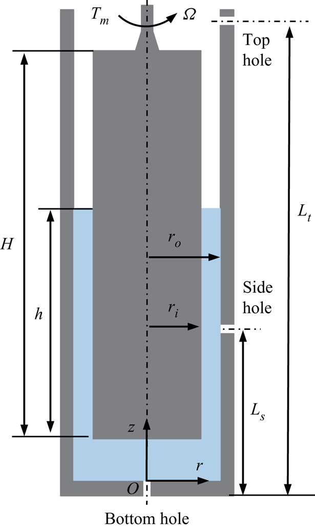
 $200$ revolutions per minute (r.p.m.). Figure 1 shows a schematic diagram of the apparatus. The inner cylinder of the TC system is directly connected to the main shaft of the viscometer and suspended in the outer cylinder. The radii of the rotating inner and the stationary outer cylinders are
 $r_i = 12.5\pm 0.02$ mm and
 $r_o = 17.0\pm 0.02$ mm, respectively, giving a radius ratio of
 $\eta = r_i/r_o \approx 0.74$ and a gap between the two cylinders of
 $d=r_o-r_i=4.5$ mm. The lengths of the inner and the outer cylinders are
 $L=91\pm 0.1$ mm and
 $L_o = 111\pm 0.1$ mm, respectively, while the gap between the bottom surface of the inner cylinder and the inner bottom surface of the outer cylinder is
 $10$ mm (we also performed experiments for gap sizes of 6 and 3 mm and it was found that the phenomenon observed is independent of the gap size). The maximum liquid annulus height is
 $H = 90$ mm, and the upper surface of the water annulus is open to the air. In our experiments the rotational speed of the inner cylinder (
 $\omega$) ranges from
 $10.47$ to
 $20.93\ \textrm {rad}\,\textrm {s}^{-1}$, which leads to
 $Re$ from
 $660$ to
 $1320$. Here,
 $Re$ is defined as
 $Re = (\omega r_i d)/\nu$, where
 $\nu$ is the kinetic viscosity of water. Depending on
 $Re$, the TC flow falls into different flow regimes which have been fully characterized by a number of studies (Di Prima & Swinney Reference Di Prima, Swinney, Swinney and Gollub1981; Andereck et al. Reference Andereck, Liu and Swinney1986; Grossmann et al. Reference Grossmann, Lohse and Sun2016). For the experimental set-up adopted in our study, the critical
 $Re$ between toroidal vortex flow and wavy vortex flow regimes is around 150, that between wavy vortex and modulated wavy vortex flow regimes is around 1000 and that between modulated wavy vortex flow and turbulent vortex flow regimes is around 1400. Thus, in this study, the flow is in the wavy vortex flow (when
 $660< Re <1000$) and the modulated wavy vortex flow (when
 $1000< Re <1320$ ) regimes. It should be noted here that all the flow vorticity maps presented in this paper were captured at
 $Re = 660$, which is in the wavy vortex flow regime. The torque exerted on the inner cylinder was measured by the viscometer. The contribution from the bearing system is subtracted automatically by the software of the viscometer; thus the torque recorded by the viscometer is directly the torque
 $T_{m}$ exerted on the inner cylinder. The error of the torque measurement is 0.2 % of the full scale of the viscometer, which is constant (
 $0.13\ \mathrm {\mu }\textrm {N}\,\textrm {m}$). Note that the measured
 $T_m$ can be divided into two parts: the contribution from the annulus flow
 $T$ and the contribution from the end flow
 $T_0$. A detailed discussion of the contributions to the measured torque is provided in appendix A. Unless otherwise specified, the torque
 $T$ throughout this paper is solely the contribution from the annulus flow (with the end flow contribution subtracted).
Schematic diagram of the TC system.

As shown in figure 1, there are three holes with a diameter of  $2$ mm in the outer cylinder allowing water to be added into or drained from the gap using a microsyringe pump, thus controlling the water annulus height
 $h$ between the two cylinders. The bottom hole is at the centre of the bottom end of the outer cylinder. The side and top holes are
 $L_s=40$ mm and
 $L_t=110$ mm away from the outer bottom surface of the outer cylinder, respectively. The thickness of the bottom end of the outer cylinder is 5 mm. It is found that our results are almost the same irrespective of through which hole the water is added or drained as the adding/draining process is very slow (of the order of 1/1000 of the maximum axial velocity of the TC flows in our experiments, a detailed discussion being given in § 3.4).
3. Results and discussion
3.1. Persistence of the vortices during the slow increase of the water annulus height
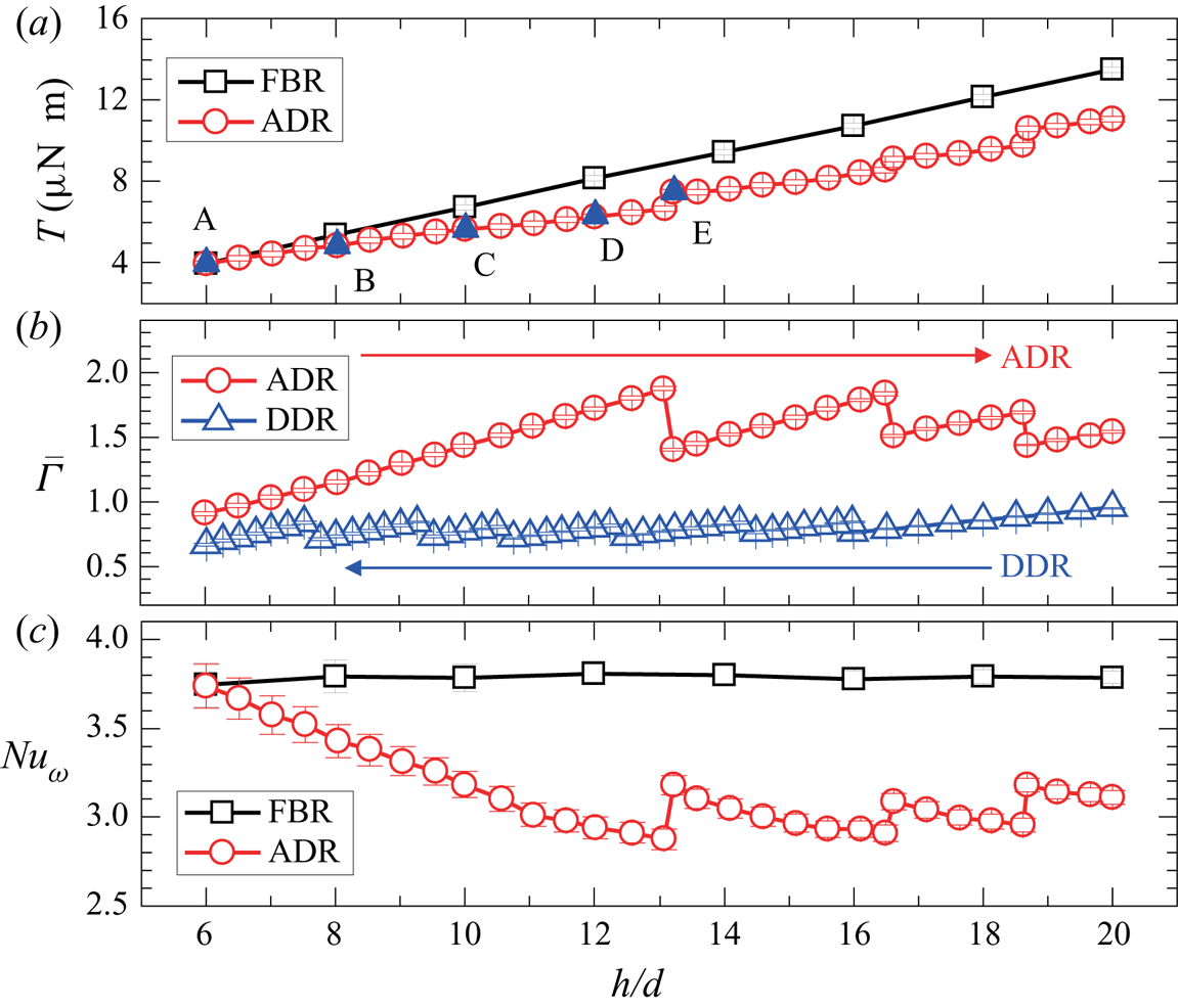
Figure 2(a) shows the torque exerted on the inner cylinder for flow prepared following the FBR and ADR procedures. For the flow prepared following the FBR procedure, we first filled the gap with deionized water to the desired height  $h=6d$, which nominally allows three pairs of vortices; then we started to rotate the inner cylinder. The inner cylinder was slowly accelerated to a rotational speed of
 $\omega =10.47\ \textrm {rad}\,\textrm {s}^{-1}$ (
 $Re = 660$) at an acceleration rate of
 $\partial \omega /\partial t = 0.105 \ \textrm {rad}\,\textrm {s}^{-2}$ which corresponds to
 $\partial Re/\partial \tau = 150$, where
 $\tau = t\nu /d^2$ is the non-dimensionalized time (by the viscous diffusion time
 $d^2/\nu$). Here
 $t$ is the time in seconds. After 1 min (corresponding to
 $\tau = 2.64$) of stabilization, the torque was measured for
 $30$ s at an acquisition frequency of
 $1$ Hz. Similarly the torques for the flow with
 $h = 8d$,
 $10d$,
 $12d$,
 $14d$,
 $16d$,
 $18d$ and
 $20d$ were measured. For the flow prepared following the ADR procedure, we first filled the annulus with water to an initial height of
 $h_0 = 6d$, then the inner cylinder was accelerated to a rotational speed of
 $\omega = 10.47\ \textrm {rad}\,\textrm {s}^{-1}$ at an acceleration rate of
 $\partial Re/\partial \tau = 150$. After that we continuously and slowly added water into the annulus with
 $h$ increasing at a speed of
 $1.58\ \textrm {mm}\,\min ^{-1}$ while the inner cylinder was kept rotating at a constant speed of
 $\omega =10.47\ \textrm {rad}\,\textrm {s}^{-1}$. As shown in figure 2(a), for flow prepared following the FBR procedure it was found that the torque
 $T$ increased linearly with the height of the water annulus
 $h$, which is consistent with previous studies (Greidanus et al. Reference Greidanus, Delfos and Westerweel2011). However, for the flow prepared following the ADR procedure,
 $T$ increased with a much smaller slope compared with the flow prepared following the FBR procedure; in addition
 $T$ exhibits several jumps (sudden increases) during the increase of
 $h$. For the same
 $h$, the torque is much smaller for the flow prepared following the ADR procedure than that for the flow prepared following the FBR procedure. For example, for
 $h = 20 d$, the torque exerted on the inner cylinder is
 $13.58 \ \mathrm {\mu }\textrm {N}\,\textrm {m}$ for the flow state prepared under the FBR condition, and is
 $11.16\ \mathrm {\mu }\textrm {N}\,\textrm {m}$ for the flow state prepared under the ADR condition, a difference of
 $17.82\,\%$. As water is slowly added, an extra torque is exerted on the inner rotor to accelerate the newly added water. If we assume that all the added water is accelerated to the azimuthal velocity on the outer surface of the inner cylinder (note that this is an overestimation), the extra torque is estimated to be
 $0.018 \ \mathrm {\mu }\textrm {N}\,\textrm {m}$, which is two orders of magnitude smaller than the smallest torque (
 $4.0\ \mathrm {\mu }\textrm {N}\,\textrm {m}$) we measured in our experiments. Thus, the torque contribution to accelerate the slowly added water is negligible.
(a) The torque  $T$ as a function of the water annulus height
 $h/d$ for flow prepared by the FBR and the ADR procedures. Points A, B, C, D and E mark the torques corresponding to the flow fields in figure 3. (b) The mean aspect ratio
 $\bar {\Gamma }=\bar {l}/d$ of the vortices as a function of
 $h/d$ measured following the ADR and ‘draining during rotation’ (DDR) procedures. (c) The Nusselt number
 $Nu_{\omega }$ as a function of
 $h/d$ measured following the ADR and the FBR procedures. The experiments were done at
 $Re = 660$.

To understand the much smaller value and the jumps of the torque exerted on the inner cylinder for the flow state prepared following the ADR procedure, we measured the flow field using the particle image velicimetry (PIV) technique in the vertical cross-sectional plane of the water annulus when  $h$ was increased from its initial value of
 $6d$ to
 $13.2d$ in the ADR procedure. As the initial
 $h_0$ is
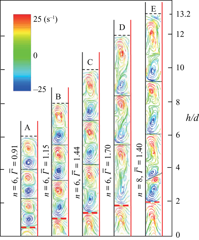
 $6d$, it nominally allows nearly six aspect-ratio-unity vortices. This is indeed the case as shown in the instantaneous vorticity maps in the first column of figure 3. Note that here the averaged aspect ratio of the vortices
 $\bar {\Gamma }$ is not exactly 1 but 0.91, because the end vortex at the bottom of the flow (separated from the main vortex pairs with red dashed lines in figure 3) is excluded when calculating
 $\bar {\Gamma }$. As our PIV measurements offer only two velocity components (
 $u$ and
 $w$), we only calculate one component of the vorticity
 $\partial u/\partial z -\partial w/\partial x$. Fortunately, this is enough for the visualization of the vortical structures at hand. Central difference was used in the calculation of the vorticity. Spurious vorticity values are detected by median test and replaced by interpolating neighbouring values.
Instantaneous vorticity maps of the flow between the cylinders in the cross-sectional plane prepared by the ADR procedure (with initial height  $h_0 = 6d$), captured when the water annulus height
 $h$ is
 $6d$,
 $8d$,
 $10d$,
 $12d$ and
 $13.2d$, respectively. The five flow fields correspond to the torques marked as A, B, C, D and E in figure 2(a). Parameters
 $n$ and
 $\bar {\Gamma }$ are the number and mean aspect ratio of the vortices, respectively. The experiments were done at
 $Re = 660$.

When  $h$ is slowly increasing, the vortices are stretched in the vertical direction. When
 $h$ is increased to
 $8d$, which nominally would allow nearly eight aspect-ratio-unity vortices, the number of vortices in the water annulus is still six, but those vortices are highly stretched in the vertical direction thus still occupying the whole height of the water annulus, as shown in the second column in figure 3. The flow is so persistent that the number of vortices remains unchanged when
 $h$ is continuously increased to
 $10d$ and to
 $12d$, but the vortices are even more severely stretched. For example, the averaged aspect ratio of the vortices
 $\bar {\Gamma }=\bar {l}/d$ becomes
 $1.70$ when
 $h = 12d$. Only when
 $h$ is increased to
 $13.2d$ is the six-vortex structure no longer sustainable; this corresponds to the bottom pair of vortices starting to split and generate a new pair of vortices. It is found that the jump of the torque occurs at the same
 $h$ when the splitting of the bottom pair of vortices occurs, which implies that the jump of the torque is due to the splitting of the vortices. Results discussed later show that it is indeed the case that each jump of the torque corresponds to a splitting of the vortices. The stretching and splitting of the vortices are clearly evidenced by the evolution of the averaged aspect ratio
 $\bar {\Gamma }$ of the vortices, as shown in figure 2(b). One can see that
 $\bar {\Gamma }$ is initially 0.91, corresponding to the initial six-vortex flow state; then it continuously increases with increasing
 $h$, which corresponds to the vertical stretching of the vortices, until it reaches 1.87. At that stage
 $\bar {\Gamma }$ suddenly drops to 1.40, which corresponds to the splitting of the vortices from the six-vortex state to the eight-vortex state; after that
 $\bar {\Gamma }$ increases again until it reaches a local maximum at
 $1.83$ and then it drops again. It is clear that the increase and the sudden drop of
 $\bar {\Gamma }$ correspond to the vertical stretching and the splitting of the vortices, respectively. From the evolution of the torque and the flow topology we can conclude that for the same height of water annulus, the flow states with fewer number of vortices generate smaller torque on the rotating inner cylinder. We also notice that for any height of the water annulus, there is a maximum axial length of the vortices, beyond which one pair of the vortices will split. The maximum axial length of the vortices can be quantified by the maximum mean aspect ratio of the vortices
 $\bar {\Gamma }_{max}$. It is found that
 $\bar {\Gamma }_{max}$ depends on the initial water annulus height
 $h_0$; for example,
 $\bar {\Gamma }_{max} = 1.87$ for
 $h_0 = 6d$, while
 $\bar {\Gamma }_{max} = 1.58$ for
 $h_0 = 12d$.
One can see from figure 2(a) that increasing the height of the water annulus is accompanied by an increase in torque. To examine the torque per unit height or the momentum flux, we have studied the Nusselt number of the TC system:
 \begin{equation} Nu_{\omega} = \frac{G}{G_{stable}},\end{equation}
where
 \begin{equation} G = \frac{T}{2{\rm \pi}\rho\nu^2h}\end{equation}
is the dimensionless torque per unit height exerted on the inner cylinder and
 \begin{equation} G_{stable} = \frac{2\eta Re}{(1+\eta)(1-\eta)^2}\end{equation}
is the dimensionless torque per unit height for the stable flow case (without vortices in the annulus) (Eckhardt, Grossmann & Lohse Reference Eckhardt, Grossmann and Lohse2007; Martínez-Arias et al. Reference Martínez-Arias, Peixinho, Crumeyrolle and Mutabazi2014; Grossmann et al. Reference Grossmann, Lohse and Sun2016). Here  $\rho$ is the density of water. Nusselt number
 $Nu_{\omega }$ represents the dimensionless angular velocity flux or momentum flux (Eckhardt et al. Reference Eckhardt, Grossmann and Lohse2007; Grossmann et al. Reference Grossmann, Lohse and Sun2016). Greater
 $Nu_{\omega }$ implies that the torque per unit height or the momentum flux is larger. As shown in figure 2(c),
 $Nu_{\omega }$ for the FBR condition remains constant with increasing
 $h$, implying that the momentum flux does not change in the FBR condition. This is not the case for the ADR condition where the overall
 $Nu_{\omega }$ decreases with
 $h$, but exhibits several jumps (sudden increases). It is now clear that the decrease of
 $Nu_{\omega }$ is due to the vertical stretching of the vortices and the sudden increases of
 $Nu_{\omega }$ are due to the splittings of the vortices. For example, the initial decrease of
 $Nu_{\omega }$ in figure 2(c) is due to the stretching of the six-vortex state, which reveals that the momentum flux between the inner and the outer cylinders decreases due to the stretching of the vortices. On the other hand, when
 $h$ increases to a value above which the six-vortex state is no longer sustainable, the bottom two vortices suddenly split, thus the number of vortices is increased by two, and at the same time
 $Nu_{\omega }$ is suddenly increased due to the stronger momentum flux. After that, with the slow increase of
 $h$ the stretching of the vortices happens again for the newly formed eight-vortex state, and the momentum flux decreases again.
3.2. Flow states with different number of vortices in the same height of water annulus
We have shown that when we start with an initial height  $h_0$ of
 $6d$, following the ADR procedure, we can maintain a sustainable flow state with 6 vortices until
 $h$ is increased to about
 $13.2d$, which allows more than 12 vortices if the flow is obtained following the FBR procedure. Thus we would expect that if we start with initial
 $h_0 = 8d$ (or 10
 $d$, 12
 $d$, 14
 $d$, 16
 $d$, …) for the ADR condition, we could maintain a sustainable flow state with 8 (or 10, 12, 14, 16, …) vortices to a height (
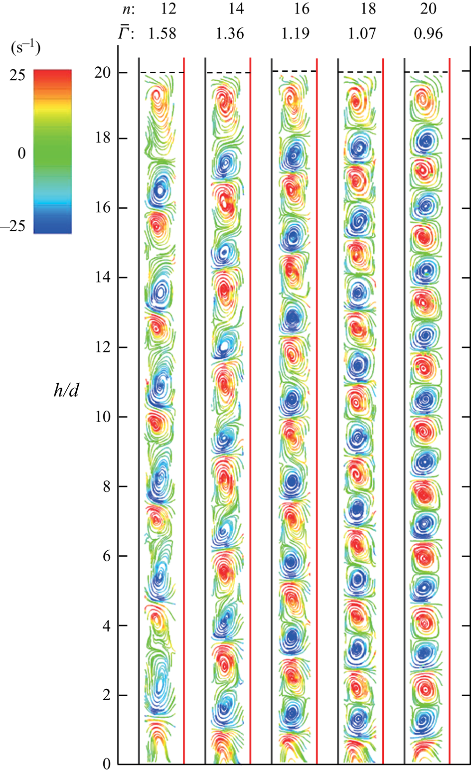
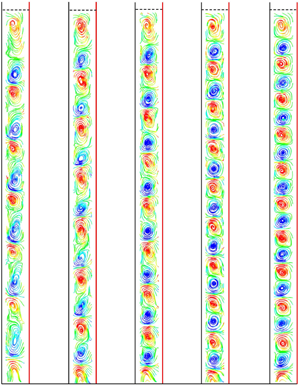
 $h$) which nominally allows many more vortices than 8 (or 10, 12, 14, 16, …). Our experiments demonstrated that this is indeed the case. As shown in the first four columns of figure 4, we achieved different flow states, in the water annulus of the same height
 $h = 20d$, with 12, 14, 16 and 18 vortices by starting the flow with initial
 $h_0$ of 12
 $d$, 14
 $d$, 16
 $d$ and 18
 $d$, respectively, following the ADR procedure. The fifth column of figure 4 is the flow obtained following the FBR procedure; it contains the nominal number (i.e. 20) of vortices.
Instantaneous vorticity maps of the five different flow states shown in figure 4, i.e. the flows for the same height ( $h = 20d$) of water annulus containing 12, 14, 16, 18 and 20 vortices, respectively. The 12-, 14-, 16- and 18-vortex flow states were achieved following the ADR procedure, while the 20-vortex flow state (shown here as a reference) was obtained following the FBR procedure. Vorticity maps were obtained at
 $Re = 660$ and water was added through the bottom hole shown in figure 1.

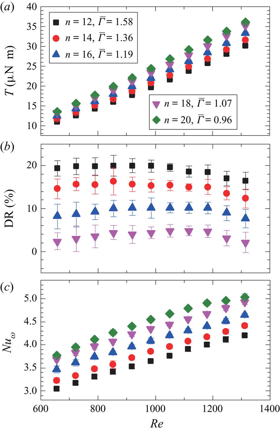
Torque measurements were then performed for the five flow states, the results being shown in figure 5(a), at different  $Re$ (different rotational speeds). For each measuring point, 30 measurements were taken at a frequency of 1 Hz and then averaged. During each measurement, the flow state was persistent and the number of vortices remained unchanged. The measured torque
 $T$ for different flow states and
 $Re$ is shown in figure 5(a), where the torque increases with
 $Re$ for all the five different flow states. The torque is much smaller for the flow states with smaller number of vortices. For example, the torque for the flow state characterized by 12 vortices is only about
 $80\,\%$ of that for the flow state with 20 vortices for
 $Re = 660$. The reduced torque (drag) on the inner cylinder can be better quantified by the drag reduction, which is defined as
 $DR=(T_\textrm {FBR}-T_\textrm {ADR})/T_\textrm {FBR}\times 100\,\%$, where
 $T_\textrm {FBR}$ and
 $T_\textrm {ADR}$ represent the torque for the flow states obtained following the FBR and ADR procedures, respectively. Figure 5(b) shows the variation of
 $DR$ as a function of
 $Re$. This initial-condition-induced drag reduction is higher for flow states with fewer number of vortices, and can be as high as
 $20\,\%$ in our experiments when we control the flow at a state with
 $12$ vortices (
 $\bar {\Gamma }=1.58$) in a water annulus of height
 $20d$. It is seen from the figure that the drag reduction does not show appreciable
 $Re$ dependence for
 $Re$ smaller than 1000, which signifies the transition of the TC flow from wavy vortex flow to modulated wavy flow, while it drops slowly for
 $Re$ greater than 1000. We also examined the momentum flux by studying
 $Nu_{\omega }$ (Eckhardt et al. Reference Eckhardt, Grossmann and Lohse2007; Grossmann et al. Reference Grossmann, Lohse and Sun2016) for the above mentioned five flow states, and found overall
 $Nu_{\omega }$ increases with
 $Re$, and, for a fixed
 $Re$ (rotation rate),
 $Nu_{\omega }$ increases with the number of vortices in the water annulus, implying that the momentum flux is increasing with the number of vortices (Martínez-Arias et al. Reference Martínez-Arias, Peixinho, Crumeyrolle and Mutabazi2014). Thus, the key point for reducing the drag is to reduce the momentum transfer between the inner and the outer cylinders by minimizing the number of vortices.
(a) The torque  $T$ as a function of
 $Re$ for the five different flow states shown in figure 4, i.e. the flows for the same height (
 $h = 20d$) of water annulus but containing 12, 14, 16, 18 and 20 vortices, respectively. The 12-, 14-, 16- and 18-vortex flow states were achieved following the ADR procedure, while the 20-vortex flow state (shown here as a reference) was obtained following the FBR procedure. (b) Drag reduction (DR) as a function of
 $Re$ for the 12-, 14-, 16- and 18-vortex flow states. (c) Nusselt number
 $Nu_{\omega }$ as a function of
 $Re$ for the 12-, 14-, 16-, 18- and 20-vortex flow states.

It should also be noted that  $Nu_{\omega }$ is in proportion to the drag per unit height (or length) for fixed
 $Re$ (
 $Nu_{\omega } \sim T/h$ from (3.1), (3.2) and (3.3)). Therefore, the drag reduction could be understood as a result of less drag per unit length in the flow state with a smaller number of stretched vortices. One might reasonably assume that, during the ADR procedure, the drag induced by one vortex increases as fast as its size when it is stretched, as more fluid is added into the stretched vortex and larger momentum flux is needed to keep the motion of all the fluid in the stretched vortex. However, this is not the case, as reflected by the fact that the vortex length nearly doubles (figure 2a), but the drag increases only by 53.8 %. As a result, the drag per unit length (
 $Nu_{\omega }$) decreases by 23.0 %. This reduced drag per unit length, due to the mismatch of the increase rates of the torque and the length of the vortices, is the origin of the drag reduction in our system.
We also notice that for any height of the annulus, there is a maximum axial length of the vortices, which corresponds to a minimum number of vortices, beyond which the vortices cannot be stretched. This is the upper bound of this drag reduction method. Limited by the rotational speed of the viscometer, we do not have results for the turbulent flow regime in this study.
3.3. The contraction of the vortices during the slow decrease of the water annulus height
We have shown that when we increase the height of the annulus during the rotation of the inner cylinder, the vortices are highly stretchable, reaching an elongation of 2.05 times their nominal length before splitting ( $\bar {\Gamma }$ changes from 0.91 to 1.87 for initial
 $h_0 = 6d$). One may ask whether these vortices are contractible when we reduce the height of the water annulus by draining the water, during the rotation of the inner cylinder (DDR). To test this, we fill the annulus with water to
 $h = 20d$, then start the rotation of the inner cylinder to rotating speed of
 $10.47\ \textrm {rad}\,\textrm {s}^{-1}$; 10 pairs of nominal vortex pairs form in the gap flow. Then we start to drain water continuously and slowly from the gap through the bottom hole with
 $h$ decreasing at a speed of
 $1.58\ \textrm {mm}\,\min ^{-1}$. The variation of the averaged aspect ratio
 $\bar {\Gamma }$ of the vortices during the DDR condition is plotted in figure 2(b). The aspect ratio
 $\bar {\Gamma }$ overall decreases with decreasing
 $h$. It also experiences several jumps during the decrease of
 $h$, each being due to the disappearance of one vortex pair. It should be noted here that for the stretch of the vortices the averaged aspect ratio of the vortices
 $\bar {\Gamma }$ is changed from 0.91 to 1.87 (for initial water annulus height
 $h_0 = 6d$), the stretchability is
 $(1.87 - 0.91)/0.91 \simeq 1.05$, while for the contraction of the vortices,
 $\bar {\Gamma }$ is changed from 0.91 to 0.67, the contractibility is
 $(0.91 - 0.67)/0.91 \simeq 0.26$. Thus, the contractability of the vortices is lower compared with the stretchability. Due to the contraction of the vortex pairs,
 $Nu_{\omega }$ measured in the DDR procedure increases slightly with decreasing
 $h$, while it also experiences sudden decreases whenever one vortex pair disappears. However, compared with the vortex stretching process, the change of
 $Nu_{\omega }$ in the vortex contracting process is much smaller. The contraction of the vortex pairs also occurs in TC flows when water is extracted from a permeable inner cylinder (Min & Lueptow Reference Min and Lueptow1994; Tilton & Martinand Reference Tilton and Martinand2018).
3.4. The splitting process of the vortices
The water added into the annulus during the ADR process is trapped in the vortex pair closest to the hole where the water is added. Thus this vortex pair is weakened and a velocity difference is induced between this vortex pair and its neighbours; this in turn leads to mass and momentum transfer between those vortex pairs which helps even out the vortex size in the annulus. If the fill rate is small, it gives time for all the vortex pairs to grow evenly before they split. While if the fill rate is high, there is not enough time for the added water to be transferred evenly to all the vortex pairs. For the latter case, the size of the vortex pair near the hole will grow faster than the others and it will split earlier, i.e. the split of the vortices will occur at a smaller  $h$. To test our hypothesis, we performed experiments with four different fill rates (
 $0.79$,
 $1.58$,
 $3.16$ and
 $6.32\ \textrm {mm}\,\min ^{-1}$). It is found that the experimental results are consistent with our hypothesis. For fill rates of 0.79 and
 $1.58\ \textrm {mm}\,\min ^{-1}$, the splitting of vortices happens at a larger
 $h$; for example, the splitting from three to four pairs of vortices happens at
 $h/d = 13.1\pm 0.5$. While for fill rates of 3.16 and
 $6.32 \ \textrm {mm}\,\min ^{-1}$, the splitting of vortices happens at a smaller
 $h$; for example, the splitting from three to four pairs of vortices happens at
 $h/d = 11.5\pm 0.5$. To compare the fill rate with the transfer scale in the system, we non-dimensionalized the fill rate by the maximum axial velocity (about
 $30\ \textrm {mm}\,\textrm {s}^{-1}$ from our PIV measurement) and a typical non-dimensionalized fill rate is (
 $1.58\ \textrm {mm}\,\min ^{-1})/(30\ \textrm {mm}\,\textrm {s}^{-1})= 8.87\times 10^{-4}$, which is a very small number. This implies that the fill rate is so small that it does not influence the flow dynamics in the system. The reason we choose the maximum axial velocity is that it represents the circulation velocity of the vortex, thus determining how fast a fluid parcel is transferred to a new location.
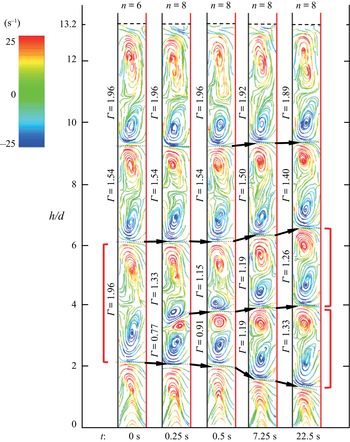
Figure 6 shows the flow topology evolution during this splitting process. When water is added from the bottom hole into the annulus, it is trapped in the vortex pair at the bottom, and the size of this vortex pair increases. As the vortex pair is continuously stretched in the vertical direction, it can no longer be sustained in stable form. This is until the moment when the highly stretched vortex pair suddenly splits into two, with a new vortex pair emerging inside the original pair. The newly formed vortices are characterized by smaller size but stronger vorticity, which increase the momentum transfer between the inner and the outer cylinder walls, thus causing a sudden increase to the torque exerted on the inner cylinder, and a higher  $Nu_{\omega }$. This pair of newly born vortices continues to grow, and finally reaches the same size as the other vortex pairs as a result of the momentum and mass transfer. The top and bottom vortex pairs in the annulus are usually stretched more heavily than the others and are more likely to split. Sometimes, these two pairs of vortices split at the same time and two new smaller vortex pairs form. Again, the mass and momentum transfer between vortex pairs helps to smooth out the size difference between them. As the water annulus height is steadily increasing, the growing and splitting process repeats.
Time evolution of the instantaneous vorticity maps of the flow in the cross-sectional plane, showing the splitting process of one vortex pair. The height  $h$ of the water annulus increases slowly at a speed of
 $1.58\ \textrm {mm}\,\min ^{-1}$. Parameter
 $n$ is the number of vortices in the water annulus and
 $\Gamma$ is the aspect ratio of the vortices. The measurement was done at
 $Re = 660$ and water was added through the bottom hole shown in figure 1.

4. Conclusion
We have shown experimentally that flow states with different numbers of vortices can be achieved in a TC system with the same water annulus height, by starting the flow at different initial conditions. It has also been shown that flow states with fewer than the nominal number of, but vertically stretched, vortices exert smaller torque (drag) on the rotating inner cylinder, compared with the flow state with nominal number of vortices of aspect ratio (nearly) unity. This inspired us to achieve drag reduction via manipulating the number of vortices through controlling the initial condition of the flow. With this method, drag reduction up to 20 % has been achieved without introducing any additive, mechanical systems or additional energy input. Further analysis reveals that the reduced drag per unit length, due to the mismatch of the increase rates of the drag and the length of the vortices, is the origin of the drag reduction in our system. Our study thus demonstrates convincingly that the momentum transfer quantified by  $Nu_\omega$ is linked to flow states characterized by vortex structures developed in the TC flow.
Acknowledgements
We are grateful for stimulating discussions with D. Lohse and C. Sun, and for the support of the NNSF of China (grant nos. 51679203, 11772259 and U1613227), the Natural Science Basic Research Program of Shaanxi (programme no. 2020JC-18), the ‘111 Project’ of China (B18041 and B17037) and the Fundamental Research Funds for the Central Universities of China (nos. 3102018gxc007, 3102019PJ002 and 3102020HHZY030014). D.D. acknowledges support through his EPSRC Established Career Fellowship (EP/N025954/1). We also acknowledge the constructive advice provided by all anonymous reviewers, which helped to substantially improve the quality of the manuscript.
Declaration of interests
The authors report no conflict of interest.
Appendix A. Measurement of the torque
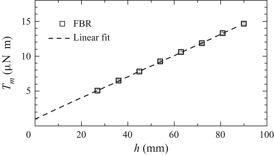
It should be noted that the torque measured by the viscometer  $T_{m}$ contains contributions both from the annulus flow and from the end flow (flow between the bottom surface of the inner cylinder and the inner bottom surface of the outer cylinder). Figure 7 shows
 $T_m$ as a function of
 $h$ for flow prepared by the FBR procedure. As shown in the figure, the contribution from the end flow can be easily obtained from the linear fit to
 $T_{m}$ versus
 $h$ data for the FBR procedure:
 $T_{m}=T_{0} + kh$, where
 $T_{0}$ is the intercept value of
 $T_{m}$ when
 $h=0$ and
 $k$ is the slope of the linear fit. The value of
 $T_{0}$ obtained from the fitting is the contribution from the end flow (Greidanus et al. Reference Greidanus, Delfos and Westerweel2011). Thus
 $T=T_{m}-T_{0}$ is the contribution from the annulus flow.
The measured torque  $T_m$ exerted on the inner cylinder as a function of
 $h$ for flow prepared by the FBR procedure at
 $Re = 660$. The dashed line is the linear fit to the data:
 $T_m = T_0 + kh$.

Appendix B. The PIV velocity measurements
In this study a two-dimensional PIV system (Dantec Dynamics) was used to measure the velocity field in the axial cross-sectional plane of the TC flow. The full resolution of the camera we used is  $2048\times 2048$ pixels and in our experiments we only used
 $92\ \textrm {pixels}\ (\textrm {width}) \times 1843\ \textrm {pixels}\ (\textrm {height})$ which corresponds to the physical size of the flow field of
 $4.5\ \textrm {mm}\ (\textrm {width})\times 90\ \textrm {mm}\ (\textrm {height})$; as a result each pixel corresponds to a physical size of
 $0.049\ \textrm {mm} \times 0.049\ \textrm {mm}$. Fluorescent polystyrene particles (MV-F07, Microvec Pte.
Ltd.) with a diameter of ~7 µm were used as tracer
particles. The excitation and emission wavelengths of the
particles are 532 and 590 nm, respectively. An optical
filter is mounted in front of the lens to make sure that
only the 590 nm emission light is captured by the camera. To minimize the optical distortion of the curved outer and inner surfaces of the outer cylinder, the TC set-up was fixed in a cubic Plexiglas tank filled with water. The tank is 11 cm in width, length and height with wall thickness of 5 mm. The tank has four vertical flat surfaces, one of which is used for laser illumination, and one, orthogonal to the one used for laser illumination, is used for image capturing. Since the refractive indexes of Plexiglas and water are very close to each other (1.49 and 1.33), the optical distortion due to the refractive index mismatch is very small and has been taken into account during the calibration of the PIV measurements. The tank also serves as a water bath to regulate the temperature of the TC system. All the experiments were done at a temperature of
 $25\pm 0.5\,^\circ \textrm {C}$ and at
 $Re = 660$.
In our TC flow the azimuthal component ( ${\sim }65\ \textrm {mm}\,\textrm {s}^{-1}$ at
 $Re = 660$), which is perpendicular to the PIV measurement plane (sectional plane of the annulus), is predominant compared with the components in the radial plane (
 ${\sim }15\ \textrm {mm}\,\textrm {s}^{-1}$ at
 $Re = 660$). We need to make sure that the time interval between the two frame-straddled laser pulses (
 $\textrm {d}t$) is short enough such that the majority of the tracer particles are still within the laser sheet after time period of
 $\textrm {d}t$; and at the same time
 $\textrm {d}t$ is long enough to make sure that the trace particles travelled appreciable long distance in the measurement plane to have good cross-correlation. The
 $\textrm {d}t$ we used in our measurement is 8 ms. Within this 8 ms, the particles travelled about 0.52 mm in the direction orthogonal to the laser sheet (azimuthal direction). As the thickness of the laser sheet is 2 mm, the majority of the particles are still inside the laser sheet. This means that the out-of-plane motion is not a problem for our PIV measurements. In the PIV measurement plane, within one
 $\textrm {d}t = 8\ \textrm {ms}$, on average the particles travelled 0.12 mm (about 2.4 pixels), which means that
 $\textrm {d}t$ is also long enough. An interrogation region size of
 $16\times 16$ pixels and an overlap of 60 % were chosen to calculate the velocity vectors. Thus, the distance between neighbouring vectors is 6.4 pixels, which is about 0.3 mm in physical space; this corresponds to the spatial resolution of our PIV velocity measurements. When the height of the water annulus is maximum (
 $h = 90\ \textrm {mm}$), we have
 $14\ (\textrm {width})\times 290\ (\textrm {height})$ vectors for one PIV velocity map. The PIV velocity measurements were done at a sampling rate of 4 Hz.
Appendix C. The open surface of the water annulus
As the upper surface of the water annulus is open to the air, due to the azimuthal velocity of the fluid, there should be surface distortion, i.e. the contact line on the inner (outer) surface of the outer (inner) cylinder should increase (decrease). As we could not measure the change of contact line on the outer surface of the inner cylinder, the distortion is defined as the height change of the contact line on the inner surface of the outer cylinder, when the inner cylinder is at rest and is rotating. Unfortunately, we found that the height of the contact line does not show appreciable change, which means that a quantitative measurement of the distortion cannot be provided. This could be due to the contact angle hysteresis on the inner surface of the outer cylinder. If we assume a linear decrease of the azimuthal velocity of the fluid along the radial direction between the inner and the outer cylinders, a simple estimation of the change of the contact lines on the inner (outer) surface of the outer (inner) cylinder can be done through balance between the pressure difference and the gravitational and the centrifugal forces combined. It is calculated that the contact line on the inner (outer) surface of the outer (inner) cylinder would increase (decrease) by 0.05 mm (0.17 mm) and 0.22 mm (0.70 mm) when the inner cylinder rotates at 100 r.p.m. ( $Re = 660$) and 200 r.p.m. (
 $Re = 1320$), respectively. The largest height change of the contact line (0.70 mm) is only 2.6 % of the smallest water annulus height (6
 $d$), and thus it can be regarded as small.