Introduction
With the revolutionary emergence of fifth-generation wireless technology, compact multi-functional components are in great demand. Among the components, filtenna, integration of antenna and filter, performs radiation and filtering operations simultaneously. Here, the antenna is devised to transmit or receive electromagnetic signals, and the filter is responsible for selecting the desired signals in the operating band while rejecting the other signals. The motive behind the design of a filtenna is to reduce the losses and size in a communication system. A few pioneering literature works are band-notched ultra-wideband planar and horn filtering antennas [Reference Tang, Wang, Deng and Ziolkowski1], planar monopole filtennas [Reference Pal, Sinha and Mahto2–Reference Wu, Yin, Zuo, Zhang and Xie4].
In the traditional filtenna synthesis technique, the last stage of filtering network is replaced by a radiating element [Reference Tang, Chen and Ziolkowski5, Reference Wu, Yin, Xie, Ren and Zuo6]. Filters designed using SIW technology and resonators can also be integrated with radiating elements to design filtennas. However, they offer narrow impedance bandwidth, which can be mitigated using a double substrate layer in the former case and defected ground structure (DGS) in the latter [Reference Mishra and Kochuthundil Lalitha7, Reference Mishra and Lalitha8]. A low-profile two-pole filtenna is designed by uniting a ground-imposed coupled line resonator with a monopole antenna [Reference Chuang and Chung9]. In another design, a filter consisting of annular resonators is integrated with a fan-shaped patch antenna to realize a flat gain in [Reference Chen, Zhao, Yan and Zhang10].
For multi-band filtering operation, filters are generally amalgamated into the feed lines of antennas [Reference Mao, Gao, Wang, Luo and Chu11–Reference Hsieh, Wu and Ma13]. The band notched operation and flexible frequency ratio can be achieved using parasitic elements in multi-band filtennas [Reference Niu, Tan and Wong14]. Alternatively, radiation nulls can also be shaped by loading shorting pins, different-shaped slots, or stacked patches [Reference Zhang, Zhang, Ye and Pan15, Reference Zhang, Duan and Pan16]. A filtenna operating at microwave and millimeter-wave frequencies is designed using a UWB bandstop filter to realize the wide-band separation [Reference Dardeer, Elsadek, Elhennawy and Abdallah17]. Additionally, the gain of printed filtenna can be further improved by using metamaterials such as artificial magnetic conductors (AMC)/high impedance surface (HIS), electronic band-gap [Reference Al-Hasan, Denidni and Sebak18, Reference Yang, Wang, Che and Wang19]. AMC/HIS is designed using a periodic arrangement of a fundamental element called a unit cell in two dimensions. The unit cell is designed such that the periodic surface offers an in-phase or 0° phase reflection and almost unit amplitude in the frequency of interest. This, along with other unique reflection and transmission properties of these surfaces, allures many applications in antennas. There are multifold reports that demonstrate performance improvement in antennas using AMC/HIS such as impedance bandwidth enhancement and gain improvement [Reference Akhoondzadeh-Asl, Kern, Hall and Werner20–Reference Elzwawi, Mantash and Denidni23].
In this communication, a dual-band filtenna is proposed for 3.3–3.55 and 5.25–5.45 GHz, which are the promising sub-6 GHz frequency bands for 5G wireless communication systems. The dual-band filtering operation is realized using λg/4 resonators inserted into the feed line of the dual-band monopole antenna operating at frequencies 3.5 and 5.35 GHz. Further, the gain of the designed filtenna is enhanced by placing it over an AMC consisting of periodically arranged metallic unit cells. The organization of the paper is as follows. Proposed filtenna design and structure are described in section “Filtenna configuration and design”. Section “Gain improvement of filtenna using AMC” details the gain enhancement of the filtenna using AMC structure. Section “Results and discussion” discusses the results and experimental verification of the proposed structures. Lastly, a summary of the work is concluded in section “Results and discussion”. The designs in this communication use FR4 substrate (ɛr = 4.3, thickness = 1.6 mm) and a loss tangent (tan δ) of 0.025. The simulated results are calculated by Computer Simulation Technique-Microwave Studio (CST MWS) software. The equivalent circuit analysis is performed using ADS, and measurements have been done using VNA and anechoic chamber.
Filtenna configuration and design
Dual-band antenna and filter
Firstly, an antenna is designed to operate in the desired bands using microstrip line-fed printed monopole technique. A printed circular monopole operating at 3.5 GHz is loaded with another monopole at 5.3 GHz, as shown in Fig. 1(a). The antenna has a partial ground plane covering up to the feed line of the antenna. A dual-band band pass filter is designed to operate at 3.3–3.55 and 5.25–5.45 GHz. A gap coupled microstrip line with 50 Ohm impedance is chosen, coupled with λg/4 resonators operating at the desired frequency bands on either side, as depicted in Fig. 1(b). The optimized dimensions of the dual-band antenna and filter are given in Table 1. Figure 1(c) depicts the characteristics of the filter. The dual-band filter operates at 3.5 and 5.3 GHz. The dual-band filter has a transmission zero around 4.1 GHz with a more than −30 dB rejection level.
(a) Dual-band antenna. (b) Dual-band bandpass filter. (c) S-parameters of the filter.

Optimized dimensions of the proposed dual-band antenna and bandpass filter

Dual-band filtenna
Next, the dual-band bandpass filter is integrated with the designed dual-band antenna to realize a dual-band filtenna operating at 3.5 and 5.3 GHz. The antenna feedline is modified with the designed filter structure, as shown in Fig. 2. The parameters are optimized to achieve the radiating as well as filtering performance at two desired operating bands. The designed structure of dual-band filtenna is shown in Fig. 2, and the optimized dimensions are detailed in Table 2.
Proposed dual-band filtenna. (a) Top view. (b) Bottom view.

Optimized dimensions of the proposed dual-band filtenna and AMC

Gain improvement of filtenna using AMC
An AMC is placed at the rear side of the proposed dual-band filtenna as a reflective surface to refine the radiation characteristics. AMC is a surface that mimics the characteristics of a PMC by providing an in-phase reflection at the resonant frequency. The unit cell of the AMC uses FR4 substrate (ɛr = 4.3, thickness = 1.6 mm). The design of the unit cell is started with a square metallic patch which gave a zero reflection phase around 3.65 GHz. An inverted L-shaped slot is etched into this, as shown in Fig. 3(a). The slot introduced another zero reflection phase at 5.3 GHz and moved the lower resonance near 3.5 GHz. The unit cell is simulated, and the reflection phase is shown in Fig. 3(a). From Fig. 3(a), it is evident that the unit cell has two zero crossings in the reflection phase centered at 3.5 and 5.3 GHz, respectively. The unit cell offers 0° phase shift in the waves reflected from its surface at these frequencies.
(a) Unit cell and its reflection phase. (b) Side view of the filtenna and AMC. (c) Proposed AMC surface.

Using this unit cell, an AMC is designed which is used as a reflective surface at the back of the filtenna. The AMC is designed with 4 × 4 array of the designed unit cell. Figure 3(c) shows the detailed structure of the AMC. The dimensions of AMC are 80 × 80 × 1.635 mm3. The filtenna and the AMC are separated by a distance hf. The optimal hf value is found to be 10 mm using parametric analysis. The side view of the filtenna with AMC is shown in Fig. 3(b), and all the dimensions are detailed in Table 2.
Results and discussion
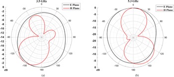
Figures 4 and 5 depict the comparison of simulated S 11 and gain of the dual-band antenna and filtenna. The antenna operates in two bands with a broader bandwidth from 2.3 to 3.8 and 4.8 to 5.4 GHz, respectively. The dual-band antenna has nearly a constant gain of 2.5 dBi in the entire band of operation. The filtenna shows a noticeable improvement in selectivity, and it resonates at 3.5 and 5.3 GHz with 10 dB impedance bandwidths of 250 and 200 MHz, respectively. The filter introduced a transmission zero around 4.0 GHz, improving the selectivity of the filtenna. The filtenna has a maximum gain of 2.5 dBi in both the desired bands of operation. It is observed that there is a considerable suppression of the gain in the undesired bands of the filtenna. The E- and H-plane radiation patterns of the filtenna at both the resonating frequencies are shown in Fig. 6. The pattern at both frequencies is omnidirectional.
Simulated S 11.

Simulated gain.

Radiation pattern of the filtenna. (a) 3.5 GHz, (b) 5.3 GHz.

An equivalent circuit model is developed for the filtenna, as shown in Fig. 7. The equivalent circuit has two parts, filtering and a radiating part. The filtering part comprises two resonators where L 1, C 1 resonate at 3.5 GHz and L 2, C 2 resonate at 5.3 GHz. C 3 is the coupling capacitor corresponding to the step at λ/4 resonator in the feedline and the circular monopole. The radiating part is shown as antenna in Fig. 7. Here, the resonator with LA 1, CA 1, and RA 1 corresponds to 3.5 GHz, and the resonator with LA 2, CA 2, and RA 2 corresponds to 5.3 GHz. L 4 and C 4 correspond to the coupling between both the resonators. The response of the equivalent circuit model is compared to that of the filtenna in Fig. 4. All the element values in the equivalent circuit model are listed in Table 3.
Equivalent circuit of the proposed filtenna.

Optimized dimensions of the proposed dual-band filtenna and AMC

The designed filtenna is backed with an AMC consisting of a 4 × 4 array of the unit cell as discussed in section “Gain improvement of filtenna using AMC” to modify the radiation characteristics of the filtenna. Figures 4 and 5 show the comparison of the simulated S 11 and the simulated gain of the filtenna and filtenna with AMC. The filtenna with AMC operates in the desired bands of frequencies as filtenna, whereas the peak gain of the filtenna with AMC in both the bands is 7.5 dBi. A remarkable gain improvement of 5 dB is observed in both the bands when filtenna is equipped with AMC as a reflective surface.
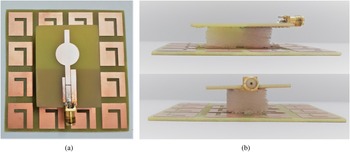
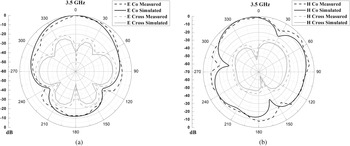
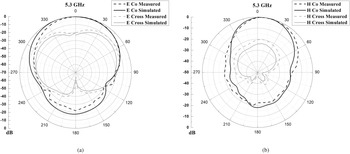
Finally, the designed filtenna with AMC is fabricated using the lithography technique and characterized. The fabricated prototype of the filtenna with AMC is shown in Fig. 8. The filtenna is placed on the AMC surface using foam with approximately unity relative permittivity. The filtenna, foam, and the AMC structure is secured using cello tape as shown in the side view of the arrangement in Fig. 8(b). Figure 9 shows the comparison of measured S 11 and gain of the fabricated prototype of dual-band filtenna with AMC with that of the CST MWS simulation. The S 11 is −19.097 and −32.169 dB at 3.5 and 5.3 GHz, respectively, with a gain of 7.505 and 7.504 dBi, respectively. It is seen that the proposed filtenna works well for 3.3–3.55 and 5.25–5.45 GHz with almost constant gain within these bands. The maximum achieved gain is 7.5 dBi in both bands. Figures 10 and 11 show the radiation pattern of filtenna with AMC in E- and H-planes at 3.5 and 5.3 GHz, respectively. The measured and simulated patterns are in good agreement. On comparing with Fig. 6, the directionality of the pattern is improved to a great extent, corresponding to the increased gain with AMC. The cross-polarization levels in the major lobe direction for E- and H-planes are observed to be −40 and −45 dB at 3.5 GHz and −28 and −30 dB at 5.3 GHz, respectively. The cross-polarization levels are well within the acceptable level for both the resonating frequencies.
Fabricated prototype of the filtenna with AMC. (a) Front view. (b) Side view.

Measured and simulated S 11 and gain of the filtenna with AMC.

Radiation pattern of the filtenna with AMC at 3.5 GHz. (a) E-plane. (b) H-plane.

Radiation pattern of the filtenna with AMC at 5.3 GHz. (a) E-plane. (b) H-plane.

Table 4 compares the proposed filtenna with some filtennas reported in the literature. Single and dual-band filtenna designs using microstrip technology are considered for comparison. It can be observed that the proposed filtenna has less circuit complexity, easy integration of filter with the antenna, and has high gain in both the operating bands. Ref. [Reference Mao, Gao, Wang, Luo and Chu11] has a higher gain which uses a 2 × 2 array of the filtenna element. For filtennas operating in the sub-6 GHz range, the proposed design offers high gain with relatively less complicated technology, ease of fabrication, and the design uses FR4 substrate making the overall design inexpensive.
Comparison of the proposed structure with filtennas reported in literature

Conclusion
The dual-band filtenna incorporated with an AMC has been proposed for gain enhancement. The proposed filtenna has a planar structure and exhibits nearly constant gain from 3.3 to 3.55 and 5.25 to 5.45 GHz, with an improvement of 5 dB. From the simulation as well as measurement, it is found that the AMC can be placed inverted without disturbing the filtenna performance and gives similar results with orientation in L-slot or inverted L-slot of AMC unit cell. Also, the proposed design can be used with or without AMC depending upon the gain requirements. All the measured results are congruent with the simulated ones. However, minute variations are due to fabrication errors or due to the SMA connector.
Conflict of interest
None.
 I. Suryarajitha received the B.Tech. degree in Electronics and Communication Engineering from Rajiv Gandhi University of Knowledge Technologies, Nuzvid, India, in 2014, and the M.Tech. degree in Electronics and Communication Engineering with specialization in Radar and Microwave Engineering from Andhra University College of Engineering, Visakhapatnam, India, in 2017. She is currently pursuing her Ph.D. degree with IIT Roorkee, Roorkee, India. Her current research interests include development of antennas and filtering antennas for microwave and millimeter-wave applications.
 Ruchi received the M.E. and Ph.D. degrees from the Department of Electronics and Communication Engineering, Thapar University, Patiala, India, in 2012 and 2017, respectively. She was with the Department of Electronics and Communication Engineering, IIT Roorkee as Post-Doctoral Fellow from November 2019 to October 2020. She has more than 9 years of teaching experience in the field of Electronics and Communication Engineering. Currently, she is working as an Associate Professor in Chandigarh University, Mohali (Punjab), India. Her current research interest includes printed antennas, filtering antennas and frequency-selective surfaces at microwave and mm-wave frequencies for 4G/5G applications, and RF energy harvesting.
 R. K. Panigrahi obtained his Ph.D. degree in Electrical Engineering from IIT Guwahati in 2011. He received his M.Tech. degree in Electronics with specialization in Microwave Engineering from CUSAT, Kochi and B.E. degree in ECE from Bangalore University. Since 2012, he has been with the Department of ECE, IIT Roorkee, where he is currently an Associate Professor. He has more than 10 years of experience in teaching and research. He has published more than 50 papers in various peer-reviewed journals and international conferences. His research interests include radar-based remote sensing, radar interferometry, radar polarimetry, development of early warning system for disaster mitigation, sensors development, networking and development of antennas for communication systems and radar applications.
 M.V. Kartikeyan received the M.Sc. and Ph.D. degrees in Advanced Electronics and Radio Physics and Electronics Engineering from Banaras Hindu University and IIT-BHU, Varanasi, India, in 1985 and 1992, respectively. He has been a Full Professor with the Department of Electronics and Communication Engineering, IIT Roorkee, Roorkee, India, since 2009. At present, he is working as a Professor in the Department of Electrical Engineering at Indian Institute of Technology, Tirupati, on deputation since October 2020. He is the principal author of five books and around 350 publications in peer-reviewed transactions/journals and conferences. His current research interests include mm-wave and terahertz engineering (sources and allied components), RF circuits, antennas and systems, metamaterials and fractals in RF domain, and RF and microwave design with soft computing techniques. He is a Fellow of IEEE (USA), Fellow of IET (UK), Fellow of IETE (India), Fellow of IE (India), and Fellow of VEDAS (India).