Introduction
Due to the rapid advancement in wireless communication technologies and the proliferation of Internet of Things (IoT)-based system design, smart wearable devices have gained more attention. These devices, such as smartwatches and fitness trackers, are the state-of-the-art section in many of the medical monitoring systems, which pave the way for the implementation of wireless body-worn communication.
Body-worn or body-centric communication is the exchange of biological data from the human body surface to an external node. Since data exchange occurs wirelessly, antennas play a crucial role in transmitting and receiving it. But unlike the antennas for other wireless systems, the antennas for body-worn applications have their own design and deployment challenges, such as compact size, light weight, flexible nature, body loading effects, bending effects, specific absorption rate (SAR), etc [Reference Abbasi, Rehman, Qaraqe and Alomainy1].
To meet the above-mentioned requirements, planar microstrip-based antennas are preferable. Also, the materials used for the antenna design have their own pros and cons, because of which materials that are highly flexible, less prone to detuning, and lighter in weight are preferred. Antennas in body-centric applications collect data across human body nodes, which is termed as on-body communication, and this requires omnidirectional radiation behavior. All the gathered information will be transmitted to an external node, which is off-body communication, which requires directional radiation behavior. It is also worth noting that using two different antennas for on- and off-body communications may violate the space constraints.
Hence, to meet the diverse radiation behavior, antenna designs supporting both on- and off-body communication (dual-mode) have been prominent [Reference Hall and Hao2].
The antennas reported in [Reference Zhao, Chao, Hong, Wang and Zheng3–Reference Ali, Awan, Naqvi, Alzaidi, Alzahrani, Elkamchouchi, Falcone and Alharbi7] support dual-mode communication. Techniques like shorting pins, annular ring slots, multilayered patch structures, multilayered substrate materials, and parasitic patches were incorporated. But they all operate only in dual narrow bands and are likely bulkier. The design complexity of the antennas is also leading to increased losses. Furthermore, to cater to the requirements of high-speed data transfer, antennas with a wide bandwidth are obligatory. From then on, ultra-wideband (UWB) technology was kick-started to be a smart solution for body-centric applications. It is a UWB technology whose spectrum ranges from 3.1 to 10.6 GHz, supporting compactness [Reference Gupta, Kumar, Bansal, Alsharif, Jahid and Cho8], wide-band, high-speed data rate in short distances, and low power consumption [9]. Also, UWB technology helps to overcome the detuning effects during on-body communications, as discussed in [Reference Gupta10]. In body-worn applications, propagation of signals outside the human body may deteriorate the reliability of signal transmission and reception, which in turn may affect the data rate as well. Also, integrating UWB technology with multiple transmitting and receiving antennas, that is, multiple input multiple output (MIMO) antennas, is a pathway to accomplish a promising data rate in emerging wearable communication with improved reliability and channel capacity [Reference Jusoh, Jamlos, Kamarudin and Malek11].
In [Reference Modak and Khan12, Reference Gupta, Kumari, Sharma, Alsharif, Uthansakul, Uthansakul and Bansal13], some recent MIMO antennas with multiband and band-notched performance are discussed. These multiband antennas, when deployed in close human proximity, experience severe detuning effects, especially at high frequencies. Hence, UWB MIMO antennas are preferred over multiband and band-notched antennas. [Reference Singh, Kumar and Kanaujia14] presents a four-port MIMO antenna with 20 mm thickness, which is not encouraging for compact scenarios. Although the flexible MIMO design in [Reference Jhunjhunwala, Kumar, Parameswaran, Mane, Kumar, Ali, Pathan, Vincent and Kumar15] is impressive with ultra-wide bandwidth and reasonable gain, the SAR of the antenna is too high for wearable applications. A two-port MIMO antenna design with an explicit decoupling structure is represented in [Reference Ali and Ibrahim16]. The antenna design using a defected ground plane supports omnidirectional radiation only and does not cover the entire UWB band as well. In [Reference Gupta, Aljaidi, Bansal, Al Mamlook, Kumar, Aljohani, Aljohani and Singla17], a coplanar waveguide (CPW)-based MIMO antenna is proposed, with reasonable gain. Focusing on implantable communication alone, the antenna operates at the 2.4 GHz ISM band only with poor gain. In [Reference Bhattacharya18–Reference Islam, Ali, Awan, Alzaidi, Alghamdi and Alathbah20], a two-element MIMO antenna with additional decoupling structures was introduced. The antenna dimensions are quite large to be used for body-worn applications. The MIMO antenna described does not work in the complete UWB range. Parasitic elements used in the structure tend to violate the space constraints and increase the design complexity as well. In all the above UWB-based MIMO antennas, a separate decoupling network has been deployed for isolation improvement. This results in more design complexity and additional design time. Also, no justified isolating structure was used for SAR reduction. Instead, the gap between the antenna and the human body was increased by trial and error, which does not seem to be methodical. The input power used for SAR analysis is also low.
For justified and methodical SAR reduction and radiation pattern manipulation, suitable isolating methods like frequency selective surface, artificial magnetic conductor (AMC), electromagnetic bandgap (EBG) structure, metasurface, etc. In [Reference Tewary, Maity, Mukherjee and Avisankar Roy21], an antenna with a square patch-shaped frequency selective surface (FSS) was used for improving the antenna gain with a large spacing between the antenna and FSS. With a very large FSS array and antenna-FSS spacing, the antenna in [Reference Tewary, Maity, Roy, Mandal, Kundu and Bhunia22] was able to achieve above 100% gain, at the sacrifice of thickness constraints. A multi-slotted FSS was used in [Reference Sugumaran, Balasubramanian and Palaniswamy23]. Both the antenna and FSS are very large with narrow bandwidth, which makes them less suitable for high data rate applications. In [Reference Renit and Raj24], the proposed FSS provides a narrow stopband, which limits its applications in wideband scenarios. Similarly, from [Reference Devarapalli, Moyra and Madhav25–Reference Das and Mandal27], the antennas are reported with FSS, considering gain improvement alone, with increased device area and thickness.
The antennas reported in [Reference Pandi Ravichandran, Velayudham and Velayudham28–Reference Venkatesh and Narmadha30] are integrated with metasurface, AMC, and dielectric-based reflector, respectively, for systematic SAR reduction and radiation pattern manipulation. Though the antennas are compact in size with a dual-mode pattern, good bandwidth, and gain, they suffer from the complete conformal nature of the device. Also, the configuration was not with MIMO, which supports more reliability and better data rates.
To summarize, the antennas in [Reference Zhao, Chao, Hong, Wang and Zheng3–Reference Ali, Awan, Naqvi, Alzaidi, Alzahrani, Elkamchouchi, Falcone and Alharbi7] provide a dual-mode pattern with good gain and low SAR, but the physical size and thickness constraints are not satisfied. Also, they suffer from narrow bandwidth limitations. From [Reference Modak and Khan12–Reference Islam, Ali, Awan, Alzaidi, Alghamdi and Alathbah20], the proposed wideband MIMO antennas achieve broad bandwidth with reasonable gain, but they don’t support dual-mode communication. They also possess shortcomings like high SAR values, an unjustified gap between the antenna and human subject, and additional decoupling structures, which limit the space provisions. Looking into the antennas from [Reference Tewary, Maity, Mukherjee and Avisankar Roy21–Reference Das and Mandal27], most of the antennas integrated with FSS structures focus only on gain enhancement and also render a narrow stop band. They also lag in attaining reduced thickness. Despite supporting both on- and off-body communications, good bandwidth and gain, the conformal nature is not viable in the works reported in [Reference Pandi Ravichandran, Velayudham and Velayudham28–Reference Venkatesh and Narmadha30].
Hence, attempting to gratify the need for unified wireless body area networks (WBANs)-based body-worn communications, in this work, a novel multi-slotted antenna design with a 2 × 2 MIMO configuration has been reported, which supports dual-mode body-centric communications with wide bandwidth and high gain. For on-body communication, the antenna uses the 2.45 GHz Industrial, Scientific, and Medical (ISM) band, and for off-body communication, the UWB band is considered. The antenna is backed with a suitable wideband FSS structure to support dual-mode operation and also to minimize the SAR values as per the Institute of Electrical and Electronics Engineers (IEEE) standards. Also, a novel extended swastika-shaped connected ground structure has been introduced, for the first time, in the ground plane to accomplish enhanced isolation. Unlike the antennas in the literature, with larger area and increased thickness, to achieve UWB characteristics, the proposed antenna is equipped with defected ground and multiple similar slots, each rotated by 45°, which are combined with the boundaries of each other. By deploying an appropriate diversity mechanism and a novel connected ground geometry, additional decoupling structures, which further limit the size constraints, were not used in the proposed antenna, yet the antenna achieved considerable isolation. Rather than using unjustified thickness between the antenna and FSS, the proposed work follows a simple mathematical model and its corresponding simulative iterations to fix the gap, which supports achieving lower SAR values. The script is structured with the antenna design part in Section “Design methodology”, free space and on-body performance in Sections “Results and discussion” and “On body performance”, respectively. Section “Transient analysis” emulates the time-domain study to verify distortionless wideband operation.
Design methodology
UWB antenna design
In this segment, the design consideration for the proposed UWB antenna is presented. To facilitate complete flexibility, Jean material is used as a substrate with a thickness of 0.8 mm, a dielectric constant of 1.67, and a loss tangent of 0.085.
The proposed UWB antenna design is shown in Fig. 1. The overall dimension of the antenna is 18 × 24 × 0.8 mm3. A microstrip line has been used for feeding the antenna. The other design steps and their evolution are shown in Fig. 2. Figure 3 depicts the equivalent resonance characteristics that can be seen in terms of return loss (S11).
Proposed UWB antenna (a – front view, b – back view). UWB = ultra-wideband.

Antenna design stages.

Simulated return loss of antenna design evolution.

The design was initiated with a circular patch aiming to resonate at 6 GHz. The corresponding patch dimensions were calculated using the following relation in Eqs. 1 and 2 [Reference Volakis31]
 \begin{equation}a = \frac{F}{{\sqrt {1 + \frac{{2h{\text{ ln}}\left( {\frac{{\pi F + 1.7726{\text{ }}}}{{2h}}} \right)}}{{\varepsilon \pi F}}} }}\end{equation}
 \begin{equation}F = \frac{{8.791\times{{10}^9}}}{{\sqrt {{\varepsilon _r}} {f_{r{\text{ }}}}}}\end{equation}
where a is the circular patch radius, h is the substrate thickness, fr is the resonant frequency, and εr is the substrate dielectric constant.
The ground plane dimensions of the antenna are calculated using the relation in Eqs. 3 and 4 as follows [Reference Venkatesh and Narmadha32]
 \begin{equation}{W_g} = {\text{ }}{W_p} + 6h\end{equation}
 \begin{equation}{L_g} = {\text{ }}{L_p} + 6h\end{equation}
For a specific substrate thickness, to satisfy 50 Ω impedance matching, the feedline width is approximated using Eq. 5.
 \begin{equation}{W_f} = {\text{ }}\frac{{7.48*h}}{{{e^{\frac{{{Z_0}\sqrt {{\varepsilon _r} + 1.41} }}{{87}}}}}} - \left( {1.25*t} \right)\end{equation}
Using all the above equations, in stage 1, a simple circular patch was designed to resonate at 6 GHz. But due to the finite ground plane effects, the resonance was observed at 6.25 GHz. Hence, to improve the resonance behavior, an annular ring-shaped slot was introduced in the patch. The resonance behavior and the dimensions of the slot are related using Eqs. 6 to 8.
The resonant frequency is given by [Reference Mohamadzade, Simorangkir, Hashmi and Lalbakhsh33]
 \begin{equation}{f_r} = {\text{ }}\frac{C}{{\pi \left( {{r_{out}} + {r_{in}}} \right)\sqrt {{\varepsilon _r}} }}\end{equation}
The initial inner radius was calculated using the relation in Eq. 7 [Reference Ravichandran P and Velayudham29]
 \begin{equation}{\text{ }}{r_{in}} = \frac{{7.15}}{{\sqrt {{\varepsilon _r}} {f_{r{\text{ }}}}}}\end{equation}
On substituting Eq. 7 in Eq. 6 and rearranging, the outer radius is modelled as
 \begin{equation}{r_{out}} = \frac{1}{{{f_r}\sqrt {{ \in _r}} }}\left( {\frac{C}{\pi } - 7.15} \right)\end{equation}
For a frequency of 6 GHz, the inner and outer radii were calculated, and the ring-shaped slot was engraved in the patch.
Due to this, strong resonances were observed at 6 GHz, 7.5 GHz with improved bandwidth. To bring the resonance to the lower side, the electrical area of the patch was increased by superimposing eight elliptical structures, each with a major axis of 6 mm and a minor axis of 4 mm. Each elliptical structure was rotated by an angle of 45°. This is shown in stage 3. A considerable shift in the resonance and improvement in bandwidth were noticed.
To achieve miniaturization and to couple multiple narrowband resonances into a wideband resonance, an eight-like slot was introduced along the curved path of the patch in stage 4. A downscaled version of circular cuts was engraved from the remaining tail end of the eight-shaped slot as well. A better match and resonance were achieved at low frequencies.
To achieve ultra-wide bandwidth, further improvement in impedance matching is required. Hence, the length of the ground plane was reduced. This phenomenon also leads to reduced Q factor and enhanced bandwidth [Reference Abdollahvand, Abbasi Arand, Katoch and Ghosh34]. An ultra-wide bandwidth of 9.35 GHz (3.75–13.1 GHz) was achieved.
The dimension of the partial ground length was calculated using the relation in Eq. 9.
 \begin{equation}
L_{\partial} = \frac{C}{{1.45f\sqrt \varepsilon }}\end{equation}
To support on-body communication at the ISM band, a resonance is created at the 2.45 GHz ISM band by lengthening a novel extended C-shaped stub in the ground plane, which is stage 5. For a stub-based resonator, the equivalent length of the stub should be  ${\text{ }}\frac{{{\lambda _g}}}{4}$ [Reference Abdollahvand, Abbasi Arand, Katoch and Ghosh34]. Taking the center frequency to be 2.45 GHz, the expected length is 26 mm. On summing the length and radius of all the portions of the stub, it results in 2 + 3 + 13 + 5 = 23 mm, which is almost close to the required length. Fixing this length, parametric analysis was done for the stub width to adjust for better impedance matching. The curved portion of the stub helps in covering the entire ISM band (2.4–2.48 GHz). As a consequence, a notch around 3 GHz occurred along with a shift in the nearby lower cutoff frequency, leading to a slight reduction in bandwidth in the UWB range.
Finally, in stage 6, an inverted pi-like slot was introduced in the ground plane exactly underneath the patch to compensate for the perturbation in bandwidth. A combination of vertical and horizontal slots increases the surface current path and shifts the cutoff frequency to a lower side. Insertion of the slot also changes the reactive nature of the impedance, thereby adjusting the electromagnetic coupling between the ground and patch. This helps in improving the bandwidth and achieving further miniaturization. The resultant bandwidth was 15 GHz (3–18 GHz).
Among the design parameters, the length of the ground plane and the horizontal length of the slot in the ground plane serve a vital role in attaining better impedance matching and bandwidth in the UWB band. Also, the width of the C-shaped stub controls the resonance and impedance behavior at the ISM band. Hence, cautious parametric analysis was carried out to achieve better results.
Let Lg be the length of the ground plane, Ls be the horizontal length of the slot in the ground plane, and Wst be the width of the stub. The simulated resonance characteristics for various values of Lg, Wst, and Ls are depicted in Figs. 4, 5, and 6, respectively.
Parametric analysis on Lg.

Parametric analysis on Wst.

Parametric analysis on Ls.

For Lg, the initial value for the design was calculated from Eq. 9, and a parametric sweep was performed. From Fig. 4, it is seen that the optimum value is 8 mm, and any value higher than that results in reduced bandwidth. For Wst, the values were increased from 2, 2.2, and 2.4 mm. An increase in width beyond 2.2 mm results in increased band-stop behavior around 2.3 to 3.1 GHz. Hence, 2.2 mm was fixed as the stub width. For Ls, as impedance mismatch occurred around 3 to 3.6 GHz, a center frequency of 3 GHz was chosen to calculate the equivalent slot length as per the suggestions in [Reference Abdollahvand, Abbasi Arand, Katoch and Ghosh34]. It is seen from Fig. 6 that 7 mm was found to be the optimum value.
MIMO antenna design
In order to ensure seamless communication with improved reliability and data rate, the proposed antenna has been configured as a quad-port MIMO antenna. The proposed MIMO antenna is shown in Fig. 7. The antennas are placed in an anticlockwise direction, such that each antenna element is orthogonal to the nearby antenna element, thereby ensuring diversity.
Proposed MIMO antenna structure. MIMO = multiple input multiple output.

This also improves the self-decoupling nature of the antenna, with satisfactory isolation achieved without deploying any decoupling structures like EBG, AMC, or parasitic elements as in [Reference Modak and Khan12–Reference Devarapalli and Moyra26].
To ensure the decoupling nature of the MIMO antenna, the transmission coefficients of the antenna are presented in Fig. 8a. With respect to port 1, the coefficients S12, S13, and S14 at ports 2, 3, and 4, respectively, were calculated. The isolation levels are less than −20 dB.
S12 of MIMO antenna (a) without connected ground and (b) with connected ground. MIMO = MIMO = multiple input multiple output.

To further reduce the coupling and enhance isolation, a connected ground structure is deployed [Reference Gupta, Aljaidi, Bansal, Al Mamlook, Kumar, Aljohani, Aljohani and Singla17]. An extended swastika-shaped connector is positioned at the center of all four ground planes. The arms of the swastika shape are extended in all four directions to be connected with the C-shaped stub in the ground plane. The conventional way of connecting the ground planes using simple horizontal/vertical metallic lines or strips [Reference Singh, Kumar and Kanaujia14, Reference Jhunjhunwala, Kumar, Parameswaran, Mane, Kumar, Ali, Pathan, Vincent and Kumar15, Reference Gupta, Aljaidi, Bansal, Al Mamlook, Kumar, Aljohani, Aljohani and Singla17], which are mostly along the boundary, results only in a trivial mutual coupling mitigation. But the proposed extended swastika-shaped connected ground renders isolation even less than −35 dB, which is certainly substantial. This is because the presence of the connecting structure in the middle of the ground slackens the disruption in surface current level, thereby creating an uninterrupted current path, which eventually outperforms the existing structures. This leads to further reduction in mutual coupling, which is shown in Fig. 8b.
It is seen that the isolation levels are considerably improved while deploying connected ground geometry in the MIMO antenna system.
Frequency selective surface design and analysis
FSS are 2D periodic structures used to enhance the antenna performance in diverse aspects. The aim of using FSS with an antenna is to reduce the SAR by reflecting the electromagnetic (EM) waves moving towards the human body. This also helps to support off-body communication.
To achieve a wide band-stop response, the corner-connected inter-rotated square ring concept was attempted, unlike using stacked layers of FSS as in [Reference Bhattacharya, Dasgupta and Jyoti35, Reference Montejo-Garai, Page, Perez-Palomino and Guirado36] or multilayered FSS as in [Reference Kushwaha, Kumar and Oli37, Reference Ranga, Matekovits, Weily and Esselle38]. The proposed FSS structure is depicted in Fig. 9. As seen from Fig. 9, the outermost and innermost square rings are placed in a conventional manner, while the intermediate ring is rotated. This is because, when the square rings are placed in a conventional manner, significant conservation in capacitive effect happens; nevertheless, the undesired inductive effect will still remain intact. Hence, to balance the capacitive and inductive effects, which in turn helps in obtaining a wideband response, the intermediate ring was rotated. This creates the required inductive effect, as the square ring corners are connected with the other two square rings, which enhances the surface current path, subsequently providing a wideband response.
Proposed FSS structure. FSS = frequency selective surface.

The structure of FSS was inspired and initiated with a simple square ring model, as it is suggestive for wideband operation [Reference Jha, Singh and Jyoti39]. The design evolution and the corresponding transmission characteristics (S21) are depicted in Figs. 10 and 11, respectively.
Design stages of FSS. FSS = Frequency selective surface.

S21 of FSS design. FSS = frequency selective surface.

The length of the initial square ring structure was approximated using the expression Eq. 10.
 \begin{equation}f = {\text{ }}\frac{C}{{4L\sqrt {\frac{{{\varepsilon _{eff}} + 1}}{2}} }}\end{equation}
To overcome the effect of grating lobes, the periodicity “p” of the FSS structure is expected to follow the inequality [Reference Jha, Singh and Jyoti39]
 \begin{equation}p\left( {1 + sin\theta } \right) \lt {\text{ }}{\lambda _0}\end{equation}
Where  ${\lambda _0}$ is the resonating wavelength. If the above inequality is satisfied, the value of p is estimated as [Reference Kundu40]
 \begin{equation}p = M{\lambda _0}\end{equation}
With this deception, the width of the FSS ring is predicted using the relation in (13)
 \begin{equation}1 = 4{\left( {\frac{L}{{{\lambda _0}}}} \right)^{2{\text{ }}}}{\text{ln}}\left( {\frac{{2M{\lambda _0}}}{{\pi w}}} \right)\end{equation}
Where “w” is the ring width and “M” is an arbitrary constant between 0 and 1 [Reference Kundu40].
The design was initiated for a frequency of 5 GHz for all the above calculations. A stopband from 3.54 to 6.95 GHz was witnessed in stage 1. Then, four stubs were extended from each corner of the ring structure to minimize the effects of spurious radiation at the corners due to the sharp irregularities. This helps in enhancing the bandwidth [Reference Kundu40]. Now, the lower frequency was shifted to 3.14 GHz, and the upper edge frequency was also shifted to 6.75 GHz. To enhance the response at high frequencies, a 45° rotated square ring was fused with the extended stubs. This extended the upper edge frequency to 10.25 GHz. But the lower edge frequency also experienced a shift to 3.68 GHz. To overcome this effect, four stubs were again extended from the corners of the rotated square ring, which shifted the lower frequency from 3.68 to 3.12 GHz while the upper edge frequency was almost the same.
To further extend the response at high frequencies, another square ring with reduced length was combined with stubs, which extended the stop band response up to 18.15 GHz. Because of the reduced length, the effect was observed only in the high-frequency region, whereas the low-frequency region remained almost intact. Thus, an ultra-wide bandstop response of 9.75 GHz (3.1 to 18.15 GHz) was achieved. The fabricated FSS prototype has been depicted as the 6th (last) stage in the design.
Holding the fact that the gap “g” between each FSS unit cell is estimated to be quite larger than the width “w”, the ratio  $\frac{{2p}}{{\pi w}}$ was set to dominate the ratio
 $\frac{{2p}}{{\pi g}}$.
This ensures minimized grating lobes, and the antenna performance with FSS shall remain modest in turn [Reference Kundu40]. As the antenna is intended for body-centric applications, the position of the human body shall vary, and hence the position and orientation of the FSS shall also be subject to undergo some changes. Hence, the study of FSS’s sensitivity to polarization and varying angles is carried out and presented in brief.
The response of the proposed FSS for transverse electric (TE) and transverse magnetic (TM) polarization modes is depicted in Fig. 12. The S21 responses desirably overlap each other, which shows the highly identical behavior of the FSS in both TE and TM polarization modes. This validates that the proposed FSS is insensitive to polarization.
S21 response for TE and TM modes. TE = transverse electric; TM = transverse magnetic.

Also, the proposed FSS was verified for its stable performance under different oblique incident angles. The responses of the proposed FSS under different oblique angles for TE and TM polarization modes are depicted in Figs. 13 and 14, respectively.
FSS response for varying incident angles under TE mode. FSS = frequency selective surface; TE = transverse electric.

FSS response for varying incident angles under TM mode. FSS = frequency selective surface; TM = transverse magnetic.

For both TE and TM modes, stable behavior of the proposed FSS up to 60° of incident angle is apparent. However, for an angular incidence of 80°, a reduction in bandwidth is seen due to frequency shifts and glitches at high frequencies.
To ensure the ability of FSS in EM shielding, shielding effectiveness (SE) was calculated using Eq. 15.
 \begin{equation}SE{\text{ }}\left( {dB} \right) = - 20\log \left[ {\frac{{{E_t}}}{{{E_i}}}} \right]\end{equation}
where Et is the transmitted wave from FSS and Ei is the incident wave on the FSS. The obtained SE is represented in Fig. 15.
Shielding effectiveness of FSS. FSS = frequency selective surface.

From Figure 15, it is clear that the proposed FSS exhibits appreciable SE, above 20 dB [Reference Kundu40], in its operating range.
Results and discussion
The performance of the FSS integrated antenna is presented in this section. FSS is placed behind the antenna to reflect the back radiation from the antenna with constructive interference. This phenomenon is represented with the side view in Fig. 16.
Side view.

As the performance of the antenna shall vary with the FSS presence behind, the required FSS configuration to be used should be finalized prior to FSS fabrication. Hence, a parametric analysis is done with various FSS array configurations, and the simulated results are presented in Fig. 17.
Parametric analysis on FSS configuration. FSS = frequency selective surface.

Three periodicity configurations, namely 3 × 3, 4 × 4, and 5 × 5 FSS arrays, were chosen. The results of the standalone antenna and the antenna with the 3 × 3 FSS arrays are almost alike. A slight shift in the lower band resonance from 2.45 to 2.41 GHz is witnessed while integrating the 4 × 4 FSS array with the antenna. Also, the bandwidth coverage extended from 2.40 to 2.48 GHz (standalone) to 2.38 to 2.63 GHz (4 × 4 FSS). The UWB coverage was shifted from 3 to 18 GHz (standalone) to 3.1 to 17.85 GHz (4 × 4 FSS). For a 5 × 5 FSS array, the resonance shifted to 2.33 GHz at the lower band, while the UWB coverage ranged from 3.15 to 17.45 GHz. Except for the lower band resonance shift for the 5 × 5 FSS array, almost stable resonance behavior is seen for all the configurations.
Hence, the analysis was extended with respect to the gain of the Antenna-FSS element, and peak gain values are tabulated in Table 1.
FSS configurations

On observing the data in Table 1, it is seen that the presence of FSS enhances the antenna gain by 95% for 4 × 4 and 103% for 5 × 5 FSS arrays. But the variation in gain improvement between the 3 × 3 and 4 × 4 arrays is 10.44% ([(9.1 − 8.15)/9.1] *100), and this variation is only 3% between the 4 × 4 and 5 × 5 arrays. The UWB bandwidth is deteriorated as well. Increasing the configuration of FSS further will result only in very minimal gain improvement at the cost of bandwidth. Hence, a 4 × 4 FSS array was fixed and fabricated for further performance analysis.
The distance between the antenna and FSS also plays a major role in the overall performance. Hence, a parametric analysis was also carried out to estimate the optimum distance between the antenna and FSS. The distance was initially approximated using the relation in Eq. 15.
 \begin{equation}{\Phi _{FSS}} + 2\beta {h_{FSS}} = 2n\pi \end{equation}
where  ${\Phi _{FSS}}$ is the reflection phase of the FSS,
 $\beta $ is the propagation constant,
 ${h_{FSS}}{\text{ }}$ is the distance between the antenna and FSS. For better reflection behavior under wideband conditions, the reflection phase shall be an integer multiple of
 $2\pi .$ To satisfy this condition, the value of n is taken to be one, and on rearranging Eq. 15, we have
 \begin{equation}{h_{FSS}} = {\text{ }}\frac{{2\pi - {\Phi _{FSS}}}}{{4\pi }}*{\text{ }}\lambda \end{equation}
where  $\beta = \frac{{2\pi }}{\lambda }$.
The reflection phase of the FSS becomes zero at 9.8 GHz, as shown in Fig. 18. On putting  ${\Phi _{FSS}}$ as zero, Eq. 16 simplifies to
 \begin{equation}{h_{FSS}} = {\text{ }}\frac{\lambda }{2}\end{equation}
Reflection phase of FSS. FSS = frequency selective surface.

The gap now is found to be 15 mm. Also, to fix the optimized distance, a parametric analysis was carried out for the gap ranging between  $\frac{\lambda }{2}$ to
 $\lambda $. The corresponding impedance characteristics and gain are presented in Table 2.
FSS distance

It is seen that the gain of the antenna with FSS at a distance of  $\frac{\lambda }{4}$ is 8.17 dB, where a 3.5 dB improvement is seen, while the bandwidth was reduced to 14.25 GHz. When the gap was increased to
 $\frac{\lambda }{2}$, gain was increased to 9.05 dB with a bandwidth reduction of 300 MHz. while increasing the distance to subsequent levels, the reduction in bandwidth becomes lesser and almost closer to the bandwidth of the standalone antenna. But the improvement in gain is only marginal. Hence, keeping in mind the space constraints, the distance between the antenna and FSS was set to
 $\frac{\lambda }{2}$ (15 mm).
Return loss (S11) characteristics
To analyze the impedance behavior of the antenna, the return loss (S11) is studied. The simulated and measured S11 of the antenna in free space is depicted in Fig. 19. The simulated and measured results are compatible with each other in both with and without FSS cases.
S11 free space.

Yet, it is noticed that the antenna’s behavior in the presence of FSS experiences a slight deviation from that of the antenna without FSS. The impedance bandwidth of the standalone antenna is 15 GHz (3–18 GHz), which is 200%, while that of the antenna with FSS is 14.75 GHz (3.1–17.7 GHz), which is 194%.
This is due to the slight impedance changes caused by the waves reflected by the FSS. But the bandwidth of the proposed antenna with FSS still covers the entire UWB spectrum.
Radiation pattern
The radiation pattern of the antenna is depicted in Figs. 20 and 21 at 2.45 and 5.8 GHz, respectively. The pattern of the antenna is omnidirectional at 2.45 GHz, which is the requirement for on-body communication, while the pattern is directional at 5.8 GHz, which is the requirement for off-body communication.
Radiation pattern of the proposed antenna 2.45 GHz (a) E-plane andd (b) H-plane. E-plane = electric-field plane; H-plane = magnetic-field plane.

Radiation pattern of the proposed antenna at 5.8 GHz (a) E-plane (b) H-plane. E-plane = electric-field plane; H-plane = magnetic-field plane.

The presence of FSS behind the antenna acts as a reflector, which reflects the antenna’s back radiation in the forward direction with constructive interference. Also, the FSS has no reflective effect on the antenna’s pattern at 2.45 GHz, as the band stop response of the FSS is out of range.
As the radiation behavior of the antenna satisfies the requirement for both on- and off-body communications, it is claimed to be a dual communication antenna for body-centric applications.
For measurements, the antenna-FSS was placed in a well-built anechoic chamber to avoid multipath reflections and ambient noise, with a double-ridged horn antenna connected with an N9951A vector network analyzer (VNA). The VNA was well calibrated within its dynamic range. The transmitting horn and the antenna under test (AUT) were properly aligned in the line-of-sight scenario to avoid positioning errors. But due to cable losses, dielectric losses, and ohmic losses, certain, but minimum, deviations exist between the simulated and measured results.
Gain and efficiency
The gain of the proposed antenna with and without FSS in free space is depicted in Fig. 22.
Gain free space.

The free space gain of the standalone antenna at 2.45 and 5.8 GHz are 2.36 and 4.2 dB, respectively, with a peak gain of 4.65 dB and an average gain of 3.5 dB, whereas the gain values are increased to 2.6 and 7.8 dB at 2.45 and 5.8 GHz, respectively, with a peak gain of 9.1 dB and an average gain of 6.25 dB when FSS is integrated with the antenna.
A good gain improvement is found in the entire UWB bandwidth with the advent of FSS by efficient reduction of undesired back radiation.
A 96% improvement in peak gain is witnessed with a 90% improvement in average gain of the antenna. However, a sudden drop in gain of the antenna is seen around 2.9 GHz. This is because of the notch behavior of the antenna at that region, which can be seen in Fig. 19.
The obtained free space efficiency of the antenna is depicted in Fig. 23. At 2.45 and 5.8 GHz, for a standalone antenna, 81% and 75% efficiency, respectively, have been achieved, which then improved to 85% and 91% with FSS integration. The peak efficiency of the standalone antenna is 82%, while that of the antenna-FSS is 94%, with an average efficiency of 77% for the standalone antenna and 88% for the antenna-FSS configuration. Substantial improvement in both peak and average efficiency is witnessed by integrating FSS with the antenna. Also, the antenna’s efficiency is consistent in the entire UWB band.
Efficiency free space.

Further improvement in gain and efficiency of the antenna, if required, shall be accomplished by improving the periodicity of the FSS, as it plays a major role in augmenting the antenna gain [Reference Ravichandran P and Velayudham29]. Usage of stacked layers of dielectric, dual metallic layers, and increasing the antenna-FSS distance shall also help to improve the antenna gain by compromising the overall volume of the antenna.
To estimate the free space performance of the proposed MIMO configuration, the following MIMO parameters are being analyzed.
Total active reflection coefficient (TARC)
In order to study the combined effects of exciting all the antenna ports in impedance matching and bandwidth, the total active reflection coefficient (TARC) is evaluated. For a four-port network is given by
 \begin{equation}{{\Gamma }}_a^t = \frac{\sqrt{\sum\limits_{n = 1}^4|{S_{n1}} + {S_{n2}}{e^{j{\theta _2}}} + {S_{n3}}{e^{j{\theta _3}}} + {S_{n4}}{e^{j{\theta _4}}}}}{2}\end{equation}
For reference, the incoming phase at the first antenna element is taken as zero. For other antenna elements, the signal phase is varied to mimic real-world signal transmission and reception. Though several phase combinations are permissible, three combinations of phase variations are considered, for brevity.
They are Case 1:  ${\theta _{1}} = {0^\circ },{\theta _2} = {30^\circ },{\theta _3} = {60^\circ },{\theta _4} = {90^\circ }$
Case 2:  ${\theta _{1}} = {0^\circ },{\theta _2} = {60^\circ },{\theta _3} = {120^\circ },{\theta _4} = {180^\circ }$
Case 3:  ${\theta _{1}} = {0^\circ },{\theta _2} = {90^\circ },{\theta _3} = {120^\circ },{\theta _4} = {270^\circ }$
The obtained TARC for the proposed MIMO configuration is presented in Fig. 24.
TARC. TARC = total active reflection coefficient.

For all iterations performed, the TARC levels remained almost similar to the S11. This ensures impedance matching and bandwidth characteristics remain robust while exciting other ports simultaneously.
Envelope correlation coefficient (ECC)
The independence exhibited by the antenna elements while working in a multipath environment is represented by the envelope correlation coefficient (ECC). A low ECC (< 0.5) ensures low correlation among the transmitted and received signals by the antenna. Orthogonal placement of antenna elements results in polarization diversity, which helps to bring down the correlation among the antenna elements. While ECC shall be extracted from the scattering parameters [Reference Bhattacharya18], the ECC presented in Fig. 25 has been estimated by the radiation properties as presented in Eq. 19.
 \begin{equation}\rho \left( {i,j} \right) = \frac{{{{\left| {\iint \limits_0^{4\pi }\left[ {{F_i}\left( {\theta ,\phi } \right)*{F_j}\left( {\theta ,\phi } \right)} \right]d\Omega } \right|}^2}}}{{{{\left| {\iint \limits_0^{4\pi }{F_i}\left( {\theta ,\phi } \right)d\Omega } \right|}^2}{{\left| {\iint \limits_0^{4\pi }{F_j}\left( {\theta ,\phi } \right)d\Omega } \right|}^2}}}\end{equation}
ECC (a) between elements 1 and 2, (b) between elements 1 and 3, (c) between elements 1 and 4. ECC = envelope correlation coefficient.

where the function  $F\left( {\theta ,\phi } \right)$ is the radiated field component of ith and jth antenna elements considered.
 $\Omega $ is the beam solid angle, and the operator * is the Hermitian product. The radiated far-field pattern obtained from simulated and measured results was used to compute the simulated and measured ECC, depicted in Fig. 25.
Adequate spatial and polarization diversity in the proposed design renders low ECC values, almost less than 0.2.
Diversity gain (DG)
The cumulative gain of the MIMO system while considering all the antennas’ radiation characteristics is given by diversity gain (DG). Essentially, a higher DG is preferred for an MIMO system for better performance. DG is estimated using the relation in Eq. 20.
 \begin{equation}DG = 10\sqrt {1 - {{\left| {ECC} \right|}^2}} \end{equation}
The obtained DG is depicted in Fig. 26.
DG (a) between elements 1 and 2, (b) between elements 1 and 3, (c) between elements 1 and 4. DG = diversity gain.

Almost the DG value remains over 9.9 dB in the entire UWB spectrum. Lower ECC results in this high DG as per the relation in Eq. 20.
Mean effective gain (MEG)
As multiple antennas are deployed in MIMO systems, the entire transmitted and received signals may become vulnerable to multipath fading. To estimate the MIMO antenna’s performance with respect to multipath fading, another crucial parameter, mean effective gain (MEG), is estimated. It is estimated using the relation in Eq. 21.
 \begin{equation}MEG = 0.5\left[ {1 - \mathop \sum \limits_{j = 1}^N |{S_{ij}}{|^2}} \right]\end{equation}
where N is the number of antenna elements. The obtained MEG is presented in Fig. 27.
MEG. MEG = mean effective gain.

For minimized multipath fading, the expected MEG is to be between −3 dB and −12 dB. This is achieved with the proposed antenna, as it can be seen from Fig. 27.
Channel capacity loss (CCL)
The allowable data rate with which the MIMO antenna system communicates depends on the loss in the channel, which is expected to be lower. This CCL is influenced by the correlation among the antennas, represented in Eq. 22.
 \begin{equation}CCL = - lo{g_2}\left( {{\text{det}}\left( {{{{\Psi }}^R}} \right)} \right)\end{equation}
Where the correlation matrix is given by
 \begin{equation}{{{\Psi }}^R} = {\text{ }}\left| {\begin{array}{*{20}{c}}
{{\psi _{11}}}&{{\psi _{12}}}&{{\psi _{13{\text{ }}}}} \\
{{\psi _{21}}}&{{\psi _{22}}}&{{\psi _{23}}} \\
{{\psi _{31}}}&{{\psi _{32}}}&{{\psi _{33}}}
\end{array}\begin{array}{*{20}{c}}
{{\psi _{14}}} \\
{{\psi _{24}}} \\
{{\psi _{34}}}
\end{array}} \right|\end{equation}
The matrix elements are given as follows
 \begin{equation}{\psi _{ii}} = 1 - \left| {\mathop \sum \limits_{n = 1}^4 {S_{in}}S_{in}^*} \right|\end{equation}
 \begin{equation}{\psi _{ij}} = - \left| {\mathop \sum \limits_{n = 1}^4 {S_{jn}}S_{in}^*} \right|\end{equation}
Looking at the CCL results in Fig. 28, it is clear that all the deduced CCL values are below 0.25 bits/Hz in the UWB range, which is less than the threshold of 0.4 bits/Hz, which is the requirement for MIMO communication with minimum channel loss and accepted data rate.
CCL. CCL = channel capacity loss.

All the above MIMO antenna parameters endorse that the proposed MIMO antenna design is well-suited for seamless, low-loss MIMO communication with reduced mutual coupling. Furthermore, they are all better than the results presented in [Reference Modak and Khan12–Reference Devarapalli and Moyra26].
On-body performance
As the antenna is accounted for in body-worn applications, its performance is also analyzed in the near proximity to the human body.
S11 and bandwidth
First, the S11 has been measured at possible human body locations, likely at the arm, chest, wrist, knee, and head, where a wearable setup can be placed. This testing setup and its S11 behavior are shown in Figs. 29 and 30, respectively. The antenna was tested on a human volunteer’s body, both with and without FSS. But a high degree of impedance mismatch has been observed while testing the antenna without FSS due to the dielectric nature of the body, which in turn affects the frequency and impedance.
S 11 on body measurement.

S 11 on body (a) without FSS and (b) with FSS. FSS = frequency selective surface.

Viewing the behavior by backing the antenna with FSS, the antenna exhibits only a minimum deviation from the free space behavior. The FSS behind the antenna acts as an isolator, which minimizes the additional dielectric effect of the human body, leading to identical free space and on-body behavior.
The measured impedance bandwidth obtained while placing the antenna at different body locations is 14.52, 14.60, 14.63, and 14 GHz, respectively, at the chest, wrist, knee, and head. Compared to other locations, deterioration in the head is greater. This is because of the oily nature of the hair follicles, affecting the effective permittivity.
Radiation pattern
The radiation pattern of the antenna under on-body conditions is shown in Figs. 31 and 32.
Radiation pattern of the proposed antenna at 2.45 GHz (on-body) (a) E-plane and (b) H-plane. E-plane = electric-field plane; H-plane = magnetic-field plane.

Radiation pattern of the proposed antenna at 5.8 GHz (on-body) (a) E-plane and (b) H-plane. E-plane = electric-field plane; H-plane = magnetic-field plane.

The antenna is placed with a four-layer tissue model whose properties are as per the suggestions in [Reference Ravichandran P and Velayudham29]. With this setup, the radiation behavior of the antenna remains almost the same as that of the free space behavior. Some slight glitches are noticed in the pattern at 2.45 GHz, which is due to the dielectric effect rendered by the tissue model. The same effect is considerably reduced at 5.8 GHz due to the presence of the FSS reflector and its operating range.
Gain and efficiency
The on-body gain and efficiency of the proposed antenna are shown in Figs. 33 and 34, respectively.
On-body gain.

On-body efficiency.

The antenna’s peak on-body gain is 8.2 dB, which is 0.9 dB less than that of the free space gain.
The average gain of the antenna is 6.07 dB. The peak on body efficiency is 82% with an average efficiency of 75.2%. Though the peak gain and efficiency values undergo a drop, they are still sufficient for unified communication.
The gain and efficiency of the antenna under on-body conditions comparatively fall from that of the free space values. The reason for this deviation (error) is that the effective permittivity of the antenna tends to vary due to the influence of the dielectric nature of the human body. To analyze the percentage error at a particular frequency, the following formula was used as per the idea in [Reference Cataldo, Monti, De Benedetto, Cannazza and Tarricone41].
 \begin{equation}\% {\text{ }}error = {\text{ }}\frac{{{G_{fs}} - {\text{ }}{G_{ob}}}}{{{G_{fs}} + {\text{ }}{G_{ob}}}}{\text{ }}\times{\text{ }}100\end{equation}
where Gfs and Gob are the gain at free space and on body conditions, respectively, at a particular frequency of interest. A similar approach was followed for error calculation in efficiency as well. Accordingly, the calculated error values are tabulated in Table 3.
Error analysis

Bend analysis
The crucial part for the antennas in body-worn applications is the maximum conformity it provides, with considerable deviations in results. To ensure this, the proposed antenna is analyzed for different radii of bending, namely 50 mm, 75 mm, and 100 mm as shown in Fig. 35.
Antenna bending (a) x-bend and (b) y-bend.

The results obtained are presented in Figs. 36 and 37 for bending in x and y orientations, respectively.
S11 on x-bend.

S11 on y-bend.

The resonance behavior of the antenna in the bending state with a 50 mm radius is almost similar to the behavior of the flat antenna. This is likely applicable for both x and y bending methods.
But for 75 mm, the frequency shifts from 3 GHz to 2.8 GHz at the lower band and from 18 to 17.5 GHz at the upper band. For 100 mm, frequency shifts from 3 GHz to 2.7 GHz and from 18 to 17.15 GHz at the lower and upper bands, respectively. A maximum bandwidth reduction of 600 MHz is witnessed. This detuning effect happens when the antenna is bent in the x-orientation, as it alters the effective length of the antenna while bending.
While performing y-orientation bending, the width of the antenna is deformed. Because of this, the impedance along the width changes due to the convergence in the feedline, resulting in changes in S11 values. This can be viewed in Fig. 29, where the S11 values fluctuate over the UWB band. For 75 mm, the S11 value was increased to a maximum of −13 dB, while for 100 mm, the same was moved to −11.5 dB. Also, at the high-frequency region, the impedance mismatch is witnessed around 16 GHz.
Though variations in S11 and detuning occur, nevertheless, the obtained bending results are still satisfactory and reasonable, as the ultra-wide band characteristics are still maintained. The results are comparatively better than the results in [Reference Pandi Ravichandran, Velayudham and Velayudham28–Reference Venkatesh and Narmadha30] due to the flexible nature of the materials used.
SAR analysis
The volume of radiation exposure experienced by the human body is represented by SAR, which is given by [Reference Padmavathy, Venkatesh, Bhargava and Sivakumar42, Reference Ramasamy, Chinnapparaj, Rajavel, Ravichandran, Farithkhan and Jenifer43]
 \begin{equation}SAR = {\text{ }}\frac{{\sigma {{\left| E \right|}^2}}}{{2\rho }}\end{equation}
where E is the electric field intensity in V/m, σ is the conductivity of the tissue in S/m, and ρ is the mass density of the tissue in kg/m3.
SAR is estimated under two scenarios, one with a four-layered tissue model whose tissue characteristics are as per the data in [Reference Devarapalli and Moyra26], while the other scenario is placing the antenna with a human phantom model. To mimic the possible wearable device placement in the human body, the antenna was placed on the human arm, chest, and thighs, as depicted in Fig. 38. The resulting SAR has been tabulated in Tables 4 and 5 for the tissue model and phantom model, respectively.
SAR analysis. SAR = specific absorption rate.

SAR values on tissue model

On observing the values, in both scenarios, increasing the gap between the antenna and human body results in reduced SAR, as reported in [Reference Ali and Ibrahim16, Reference Bhattacharya18, Reference Bhattacharya, Roy, De, Chakraborty and Mallik19, Reference Ravichandran P and Velayudham29]. But this may violate the spacing constraints and compactness. Hence, an FSS layer behind the antenna pulls down the SAR to the limits specified by IEEE C95.3.
It shall be noted that the SAR obtained in the FSS presence limits the radiation exposure within 1.6 W/Kg. The advent of FSS has a substantial impact on SAR reduction, thereby warranting reduced radiation hazards.
Path loss
Path loss is experienced during the propagation of EM waves through/across any wireless medium. It is given by [Reference Narmadha44]
 \begin{equation}PL = - 10{\text{ log}}\left( {\frac{{{G_t}{G_r}{\lambda ^2}}}{{{{\left( {4\pi d} \right)}^2}}}} \right)\end{equation}
where Gt is the gain of the transmitting antenna, Gr is the gain of the receiving antenna,  $\lambda $ is the wavelength, and d is the distance of separation.
SAR values on human phantom

In body-worn applications, the EM wave propagation occurs in a wireless medium aside the human body and free space. Hence, estimation of path loss is carried out for free space and on- & off-body conditions too. Figures 39, 40, and 41 depict these scenarios, respectively.
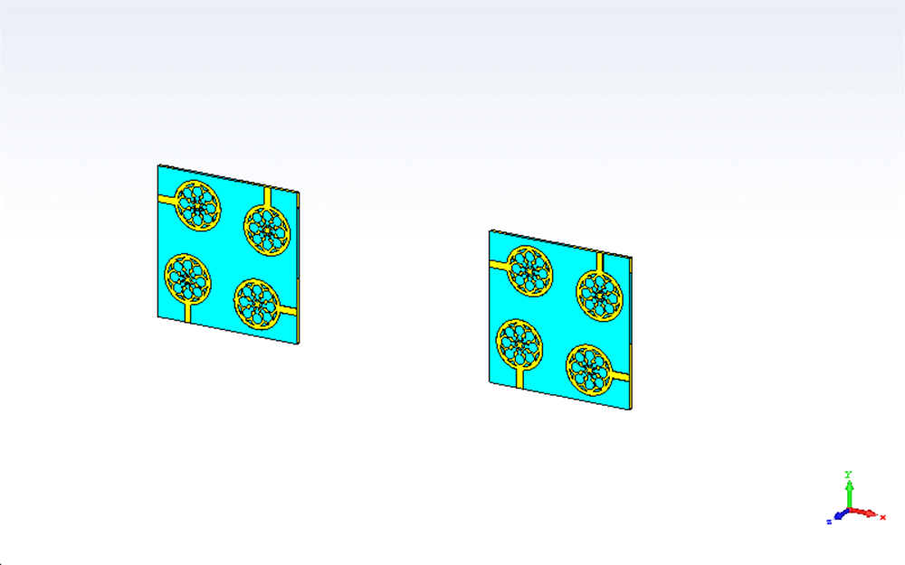
Free space path loss simulation.

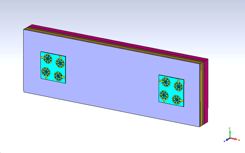
On-body path loss simulation.

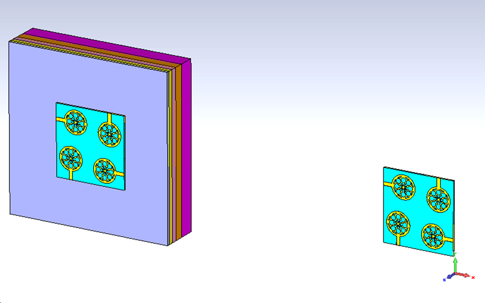
Off-body path loss simulation.

Two of the proposed antennas were placed side by side, separated by 100 mm and 200 mm distances. Both the antennas were backed with the tissue model for 100 and 200 mm distances, considering that the signal transmission occurs completely outside the human body (on body). While for off-body transmission, one antenna is used with a tissue model, whereas the other antenna is left without any tissue model, assuming that the signal transmission occurs from the human body to an external node. To compare the performance of the above-mentioned scenarios, a free space transmission setup was also modeled, where both antennas are without any human model behind them.
The amount of attenuation experienced during the transmission across the human body model is represented by the attenuation factor in Eq. 28.
 \begin{equation}{\alpha _{b{\text{ }}}} = {\text{ }}\frac{\sigma }{2}{\text{ }}\sqrt {\frac{{{\mu _0}}}{{{ \in _0}{\text{ }}{\varepsilon _r}}}} \end{equation}
where  $\sigma $,
 ${ \in _0}$, and
 ${\mu _0}$ are the conductivity, permittivity, and permeability, respectively, in free space,
 ${\varepsilon _r}$ is the permittivity whose values are taken as in [Reference Venkatesh and Narmadha32]. Expressing the term in (20) in dB, we obtain
 \begin{equation}{\alpha _{b\left( {dB} \right){\text{ }}}} = {\text{ }}\frac{{520.8\pi \sigma }}{{\sqrt {{\text{ }}{\varepsilon _r}} }}{\text{ }}\end{equation}
Now, Eqs. 28, 29 and 30 are together represented as Eq. 31.
 \begin{equation}PL{\text{ }}\left( {dB} \right) = - 10\log \left( {\frac{{{G_t}{G_r}{\lambda ^2}}}{{{{\left( {4\pi d} \right)}^2}}}} \right) + \frac{{520.8\pi \sigma }}{{\sqrt {{\text{ }}{\varepsilon _r}} }}{\text{ }}\end{equation}
The path loss obtained is presented in Table 6.
Path loss of the proposed antenna

It is verified that the path loss for the on-body condition is comparatively higher than for other conditions. The reason behind this is the drop in gain of the antenna under on-body conditions and the effect rendered by the additional attenuation factor.
Transient analysis
In wideband systems, analyzing the pulse handling capability becomes more important, as they are vulnerable to pulse distortion. Hence, fidelity and group delay analysis are discussed in this section.
Fidelity factor (FF)
The correlation metric between the transmitted and received pulses is represented by the fidelity factor (FF). It is estimated by the expression below
 \begin{equation}FF = max\smallint \limits_{ - \infty }^\infty {T_s}{\text{ }}\left( t \right){\text{ }}{R_s}{\text{ }}\left( {t + {\text{ }}\tau } \right){\text{ }}dt\end{equation}
where Ts(t) – transmitted signal, Rs(t +  $\tau $) – received signal with delay.
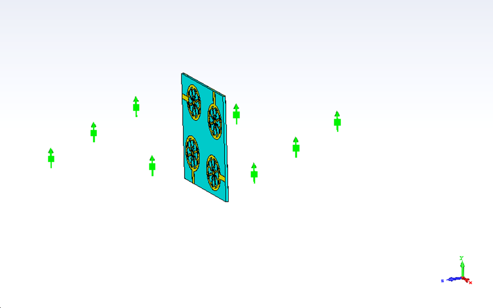
The setup for estimating FF is shown in Fig. 42.
Fidelity factor simulation.

The proposed antenna acts as a transmitting antenna, while several receiver field probes are placed around the antenna with 30° angular separations. The transmitted and received pulses are applied to Equation 32, and the values are estimated using Python coding [Reference Pandi Ravichandran, Velayudham and Velayudham28].
Table 7 represents the obtained FF values. For each angular separation, the FF remains more than 0.5, which is the suggested value of FF [Reference Cataldo, Monti, De Benedetto, Cannazza and Tarricone41, Reference Padmavathy, Venkatesh, Bhargava and Sivakumar42]. The existence of a correlation between the transmitted and received pulses is evident from this, ascertaining minimum pulse distortion.
FF of the proposed antenna

Group delay
During the transmission and reception of signals in UWB systems, the distortion experienced in the phase of the signal is given by the group delay. It is given as follows
 \begin{equation}{T_g} = {\text{ }}\frac{{ - d\varphi }}{{d\omega }}\end{equation}
where Φ – phase of signal and ω – angular frequency.
For three conditions, namely free space, on-body, and off-body, group delay was estimated. The simulation setup used for deducing the group delay is the same as the one depicted in Figs. 39, 40, and 41. The estimation was made from port 1 of the first antenna and port 2 of the second antenna. The obtained group delay is presented in Fig. 43.
Group delay: (a) face to face and (b) side to side.

The results in Fig. 43 show that the fluctuation in group delay is minimum, within 1.5 ns, which is the acceptable range [Reference Venkatesh and Narmadha45]. This value in the time domain ensures minimum variations in the signal’s phase.
Table 8 presents the comparison data of the proposed work with the other existing work. To ensure the device compactness, the size of the single antenna element, thickness, antenna – FSS gap and FSS dimensions are compared. To emphasize the dual-mode behavior, the radiation pattern is compared, followed by comparing the essential parameters like bandwidth and gain.
Performance comparison

*nb = narrow band; NE = not evaluated; WB = wide band.
The comparison shows that the proposed antenna stands out with a good performance trade-off among the parameters compared. It remains smaller in dimensions, thickness, and possibly a small antenna-FSS gap, supporting dual-mode radiation in parallel. The bandwidth and gain of the antenna also dominate most of the other existing works’ values. The overall volume of the proposed MIMO is much lesser than the existing antennas, with reduced mutual coupling without any decoupling structure, diversity, or flexibility being add-ons.
Conclusion
A compact, flexible UWB MIMO antenna embedded with interrotated square ring FSS structures has been discussed in detail. The 15 GHz impedance bandwidth of the antenna covered the entire UWB spectrum with a peak gain of 2.65 dB without FSS, which was then elevated to 9.1 dB on the advent of FSS with the antenna. The FSS ring structures were inter-rotated and connected with corners to obtain a wide stopband response. With a 4 × 4 FSS array behind the radiator, the antenna was able to support on and off-body communications with a reduced SAR of 0.69 and 0.32 W/kg at 2.45 and 5.8 GHz, respectively. All the obtained MIMO diversity parameters are promising and dominate the existing antennas, ensuring enhanced reliability and data rate. Antenna measurements were carried out on the human body surface, where an acceptable deviation was witnessed from free space measurements. The path loss and the variations in group delay are also minimal. The obtained fidelity values prove the pulse resemblance between the transmitter and receiver. From the discussions and comparisons made, the proposed antenna remains a successful candidate for body-centric wireless applications.
Competing interests
The authors declare hereby that there is no competing interests in publishing the paper in any form.

P. Venkatesh received his BE degree in Electronics and Communication Engineering from Anna University, Chennai, India, in 2013 and his ME degree in VLSI Design from Anna University, Chennai, India, in 2015. He is currently working as a faculty member in the Department of Electronics and Communication Engineering, Ramco Institute of Technology, Tamil Nadu, India. His areas of interest are Wearable Antennas, Ultrawideband Antennas, Electromagnetic Bandgap Structures and Artificial Magnetic Conductors, and Frequency Selective Surfaces.

M. Ponnrajakumari received the Engineer degree in Electronics and Communication Engineering from Jayaram College of Engineering and Technology, Tiruchirapalli, Tamil Nadu, India, in 2001. She received the Master’s degree in Digital Communication and Network Engineering from Arulmigu Kalasalingam College of Engineering, Krishnankoil, Tamil Nadu, India, in 2006. She received a PhD degree from Anna University in 2023 in the field of research on Cognitive Radio Networks. She is currently working as an Assistant Professor in the Department of Electronics and Communication Engineering at Velammal Engineering College, Chennai, India. Her areas of interest include Wireless Networks, Cognitive Radio Networks, Cybersecurity, and Internet of Things.

T. V. Narmadha received her AMIE degree from the Institution of Engineers, India, ME and PhD degrees from the College of Engineering, Anna University, Chennai. She has more than 21 years of teaching experience. She is currently working as a faculty member in the Department of Electrical and Electronics Engineering. She has published more than 30 research papers in national/international journals/conference proceedings. Her teaching and research interests include Electrical Drives, Medical Image Processing, Auto-tuning, Control Using Fuzzy Logic, Neural Networks, and Genetic Algorithm.

R. Ramasamy received his ME from Anna University, Chennai, India, and his BE in Electronics & Communication Engineering from Anna University, Chennai, India. He is a life member of He is working as a faculty member in the Department of Electronics & Communication Engineering at Ramco Institute of Technology, Rajapalayam. Some of his research has been published in Web of Science, Emerging Sources Citation Index (Clarivate Analytics), Scopus, and reputed peer-reviewed journals, and he has presented research papers at various international and national conferences. His research interests include antenna design, antenna design for 5G and 6G communications, and machine learning in antenna design.

S. A. Radhika received her BE degree in Electronics and Communication Engineering from Anna University, Chennai, India, in 2017 and M.E degree in Communication Systems from Anna University, Chennai, India, in 2019. He is currently working as a faculty member in the Department of Electronics and Communication Engineering, Mepco Schlenk Engineering College, Sivakasi, India. Her areas of interest are Electromagnetic Bandgap Structure and Beamforming Antenna Arrays.

T. V. Padmavathy is a Professor in the Department of ECE at R.M.K. Engineering College, has 21 years of teaching and research experience in the fields of Wireless sensor networks, Underwater Acoustic Sensor Networks, and Antenna Design. She has graduated from the Institution of Engineers (India) in Electronics and Communication Engineering. She has obtained her Master’s degree in Control and Instrumentation from College of Engineering, Guindy, Anna University, Chennai, India, and Ph.D. degree from Anna University, Chennai, India. She has published more than 50 research papers in International and National Journals and conferences in the areas of Mobile Ad hoc Networks, Wireless sensor networks, Under Water Acoustic Sensor Networks, and Antenna design.