Introduction
With the development of wireless communications, microwave filters are key components to select frequency signals [Reference Li, Zhang, Li and Li Joshua1, Reference Li, Zhang, Feng and Fan2]. Ultra-wideband (UWB) bandpass filters (BPFs) have been a hot topic in the UWB system front end since they affect the performance of the entire system [Reference Wei, Wu, Shi and Li3, Reference Wei, Xu, Shi and Liu4]. Multi-mode resonator (MMR) technology and highpass–lowpass combination technology are widely used to implement UWB filters [Reference Rui, Wong, Zhu and Chu5–Reference Zhang, Zhang and Chen13]. However, compared with highpass–lowpass combination technology, there have been few attempts to design substrate-integrated waveguide (SIW) UWB BPFs in MMR technology, and these filters are confronted with complex design procedures, large circuit sizes, multi-layer structures, and undesirable interference problems [Reference Zhou, Guo, Zhou and Wu11–Reference Zhang, Zhang and Chen13]. In [Reference Zhou, Guo, Zhou and Wu11], a UWB BPF is designed using hybrid half-mode SIW (HMSIW) – microstrip hybrid structure. However, the structure has a deteriorated quality factor, and it suffers undesired interference caused by coexisting wireless services, which can be mitigated by using a notch structure. A UWB filter using a SIW ridged MMR integrated on the multi-layer structure is designed in [Reference Honari, Mirzavand, Saghlatoon and Mousavi12]. However, the undesired interference within the passband has not been mitigated. In [Reference Zhang, Zhang and Chen13], a notch-band wideband BPF integrated on a multi-layer SIW circuit was designed using a quad-mode one-third isosceles triangular resonator, but it covered a limited 3 dB fractional bandwidth (FBW), only accounts for 33.33%, which cannot adequately supply a UWB passband. In addition, multi-layer SIW structure implementations are challenged by alignment and fabrication complexity problems [Reference Honari, Mirzavand, Saghlatoon and Mousavi12, Reference Zhang, Zhang and Chen13]. Until now, the design of UWB BPF based on a planar SIW MMR is a big challenge.
On the other hand, defected ground structure (DGS) embedded inside the SIW structure are commonly utilized to create UWB passbands [Reference Rui, Wong, Zhu and Chu5–Reference Zhou, Guo, Zhou and Wu11], rather than notched bands within the UWB passbands. In [Reference Esmaeili and Bornemann6, Reference Ding, Wei, Li and Shi10, Reference Zhang, Zhang and Chen13], although the notched bands are reported using DGS embedded inside HMSIW or SIW circuit, this approach is applied to design bandstop filters, rather than notched bands within UWB passbands. The notched bands within SIW wide passbands are designed by introducing extra circuits outside the SIW structure [Reference Hinojosa, Rossi, Saura-Rodenas, Alvarez-Melcon and Martinez-Viviente14, Reference Esmaeili and Bornemann15], which undoubtedly requires an additional circuit for notch structure so that large-scale circuit layout is inevitable. To the best of the authors' knowledge, no paper has been reported about the realization of notched bands within a UWB passband using DGS embedded inside the SIW circuit.
This paper firstly proposes a perturbed HMSIW cavity resonator and its single-cavity application to design a UWB BPF with a notched band using a complementary split-ring resonator (CSRR). Five resonant modes are perturbed using four loaded stubs, and they are allocated to the specified frequencies in the UWB passband. In addition, a CSRR embedded inside HMSIW is employed to construct a notched band for the first time. The proposed filter is very suitable for UWB system applications.
Design procedures
HMSIW resonator
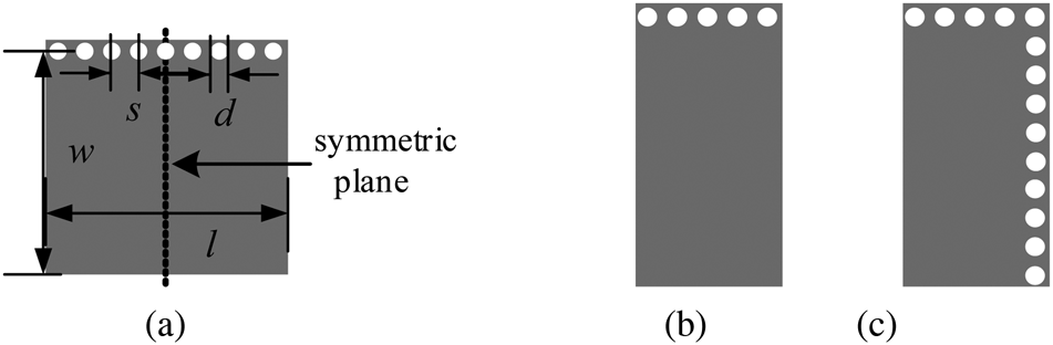
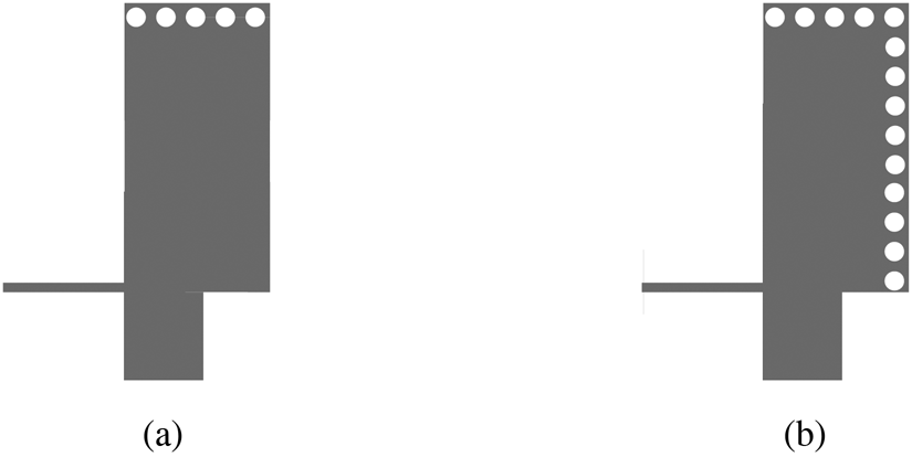
Figure 1(a) shows the geometric layout of a square HMSIW resonator. It consists of three magnetic boundaries and an electric boundary [Reference Chen, Song, Hu and Fan16]. The even/odd mode theory is adopted to analyze its working mechanism owing to its symmetry structure. The even-mode equivalent model in Fig. 1(b) not only transmits SIW cavity resonant mode – TE102 mode, but also can be regarded as a short-circuited quarter wavelength microstrip-line resonator transmitting quasi-TEM mode. The resonance frequencies of the fundamental and higher quasi-TEM modes can be calculated by using the transmission line theory [Reference Wang, Zhang, Zhang, Qing and Zhou17].


(a) Layout of the HMSIW resonator, (b) even-mode and (c) odd-mode model of the resonator, d = 0.6, s = 0.9, w = 9.45, and l = 9.45 (all in mm).

while that of the TE102 mode can be calculated by

The odd-mode equivalent structure excitation in Fig. 1(c) is equivalent to a quarter-mode SIW resonator providing TE101 and TE103 modes, whose resonance frequencies are extracted by


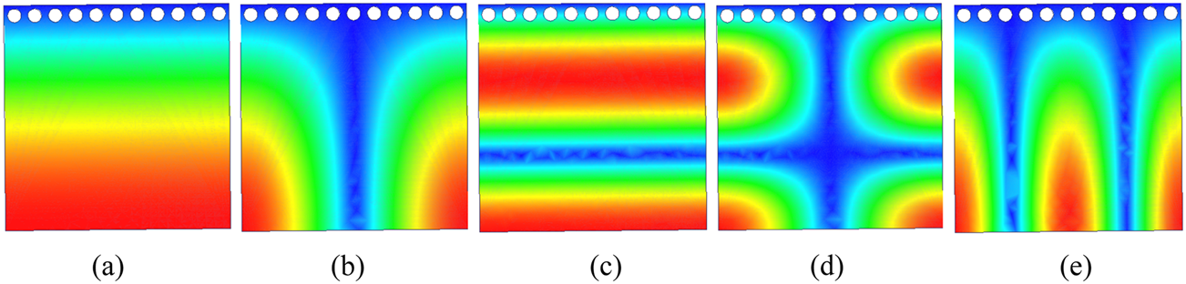
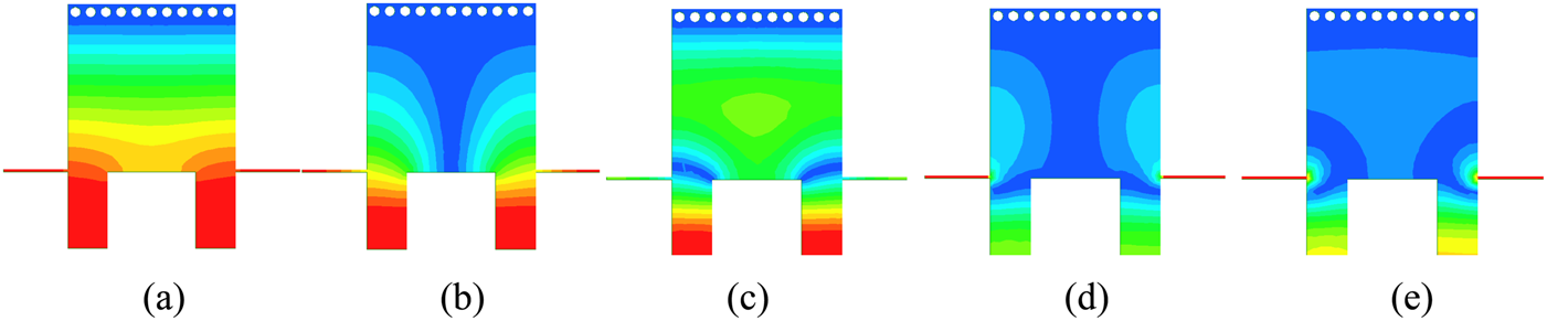
where c 0 is the speed of light in free space and ɛr is the relative permittivity of the dielectric substrate. The dimensions of the resonator can be calculated by (1–5) with w = l = 9.45 mm. Using the commercial electromagnetic simulation software HFSS, the electric field distribution of the first five degenerate modes are obtained, as shown in Fig. 2. They can be differentiated as even or odd modes based on their electric field distributions at the symmetrical region. Due to the strong electric field distributions at the symmetrical region, the first and third resonant modes are characterized as even modes transmitting quasi-TEM, as shown in Figs 2(a) and 2(c), while that of another even mode transmitting TE102 mode is shown in Fig. 2(e). Likewise, Figs 2(b) and 2(d) depict the electric field distributions of the first two odd modes, TE101 and TE103, respectively.
Electric field magnitude distributions of the first five resonant modes, (a) even mode 1, (fe 1), (b) odd mode 1 (fo 1), (c) even mode 2, (fe 2), (d) odd mode 2, (fo 2), and (e) even mode 3, (fe 3).

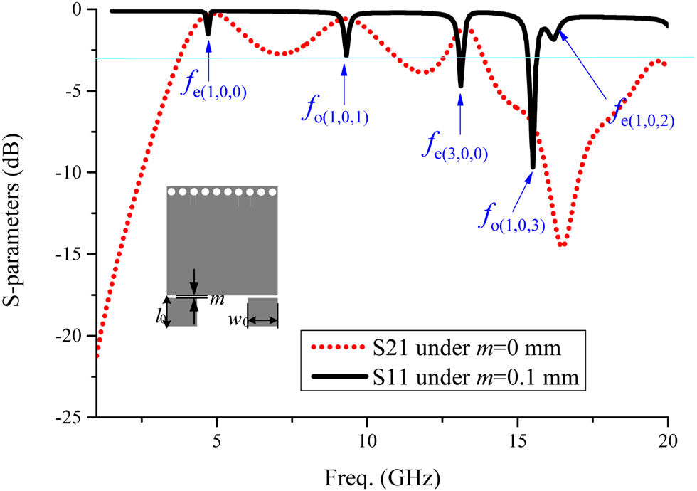
The transmission response of the HMSIW BPF without any perturbation is depicted in Fig. 3. The microstrip feed lines with a width of w 0 and a length of l 0 are arranged at two corners formed by the magnetic walls. As can be seen, a transmission zero (TZ) is generated at the upper stopband due to the excitation of higher order modes in the cavities. However, the resonant frequencies of the first five modes are too far to form a bandpass frequency response. To improve the performance of the filter, the perturbation technique will be presented and analyzed in the following sections.
Transmission response of the HMSIW bandpass filter, w 0 = 1.13 and l 0 = 1 (all in mm).

Perturbed HMSIW resonator
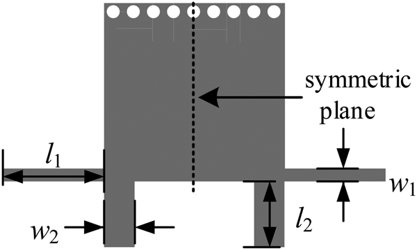
The configuration of the perturbed HMSIW resonator is presented in Fig. 4, which is constructed by loading four stubs on the two corners formed by the magnetic walls. The working principle of the conventional HMSIW resonator can be applied to analyze the proposed resonator.
Layout of the perturbed HMSIW resonator.

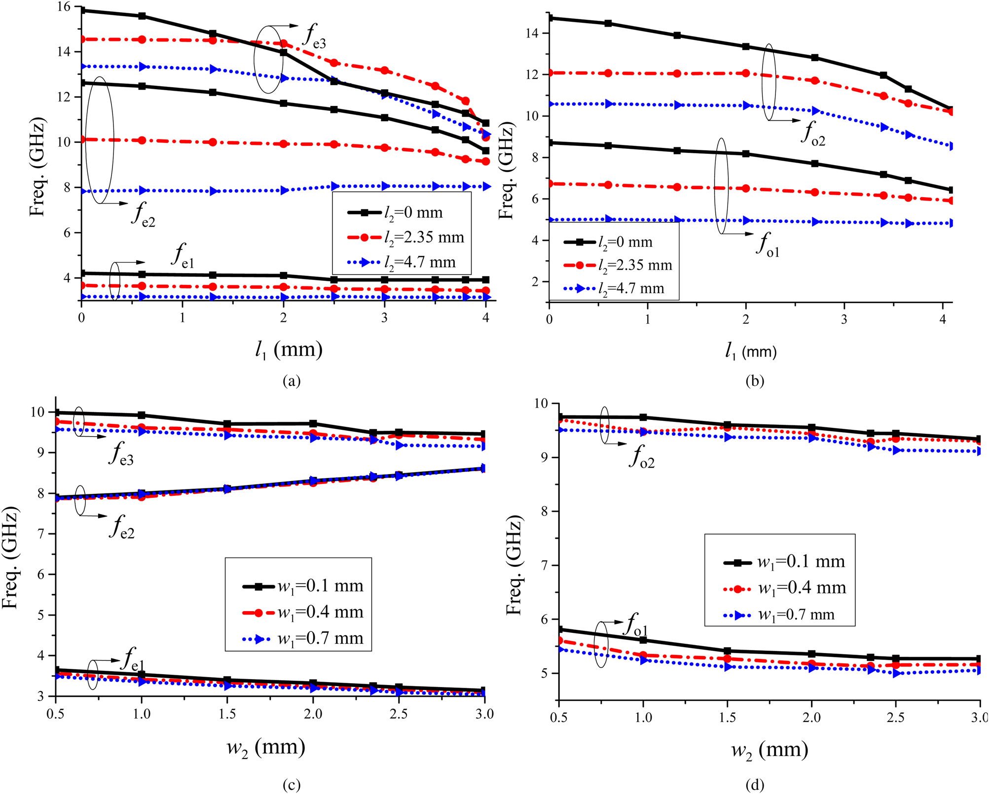
Even/odd mode theory is also utilized as shown in Figs 5(a) and 5(b). According to the models shown in Figs 1(b) and 1(c), the working area of the actual circuit is increased with the loaded stubs, thus the frequencies of TEm0p modes are reduced. For the quasi-TEM mode excitation in Fig. 5(a), the loaded stubs make the circuit behave as a short-circuited stepped-impedance resonator, which can effectively reduce the frequencies of high harmonics thereby further reducing the circuit size. To illustrate clearly, the frequency response of the first five resonant modes, three even modes and two odd modes, versus l 1, l 2, w 1, and w 2 is investigated in Fig. 6. In Figs 6(a) and 6(b), w 1 and w 2 are set as 0.15 and 2.34 mm, respectively. In Figs 6(c) and 6(d), l 1and l 2 are set as 3.8 and 4.5 mm, respectively. As can be seen, the resonant frequencies decrease greatly with the increase of l 1 and l 2, while they decrease slowly with the increase of w 1 and w 2. Based on the curves and equations, the variable parameters, l 1, l 2, w 1, and w 2, are selected to provide five resonant modes within the predetermined passband during the tuning process.
Models (a) even-mode and (b) odd-mode.

Resonance frequencies characteristics of (a) even modes varying with l 1, l 2, (b) odd modes varying with l 1, l 2, (c) even modes varying with w 1, w 2, and (d) odd modes varying with w 1, w 2.

Figure 7 presents the electric field magnitude distributions at the five resonant modes. As can be seen, the electric field magnitude distributions of mode (1–3) are strong at the loaded stubs, while that of mode (4–5) is a little weak. Therefore, strong external coupling can be implemented by locating the microstrip feed lines on two broad-edge loaded stubs.
Electric field magnitude distributions of the first five resonant modes (a) even mode 1, (fe 1), (b) odd mode 1 (fo 1), (c) even mode 2, (fe 2), (d) odd mode 2, (fo 2) and (e) even mode 3, (fe 3).

Notched band design
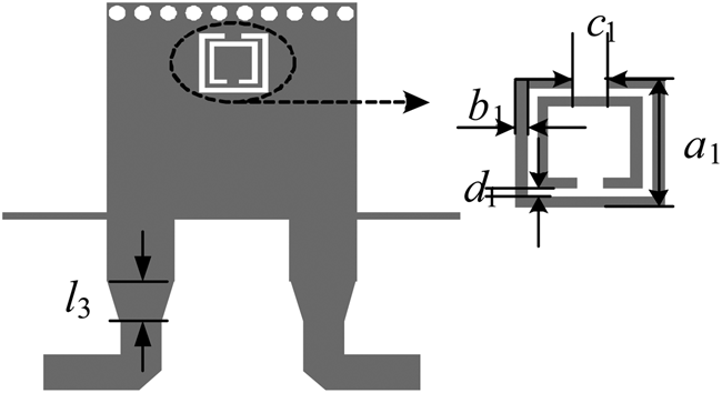
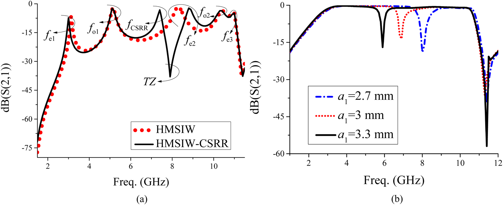
To implement a notched band within the UWB passband, a CSRR embedded inside the SIW circuit is firstly proposed, whose geometrical structure is shown in Fig. 8. It consists of a UWB BPF geometrical structure and a CSRR etched on the HMSIW top metal plane. A transmission pole (TP) would be produced when the CSRR is excited by the HMSIW resonator. Meanwhile, the coupling between the CSRR and the resonator is mixed electromagnetic coupling, and hence producing a TZ. By allocating the TZ within the passband, a notched band would be implemented. To demonstrate clearly, Fig. 9(a) depicts the simulated S-parameters of HMSIW and HMSIW-CSRR under weak coupling, respectively. An extra TP and a TZ could be clearly observed, which are consistent with the predicted results. In this way, allocating the TZ within the passband can generate a notched band. From Fig. 9(b), we can find that the position of notched bands can be flexibly controlled with varied a 1. Due to the working mechanism, the bandwidth of the notch can be controlled by controlling its external coupling, which can be controlled by the geometrical structure of CSRR. Therefore, this method is validated for designing a notched band.
Layout of the proposed notched band UWB BPF.

(a) Simulated S21 of HMSIW-CSRR under weak coupling, and (b) simulated S21 of HMSIW-CSRR varying with a 1.

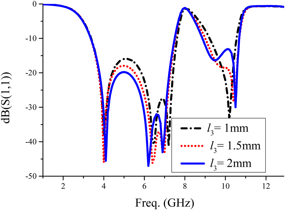
Meanwhile, the tapered transition between the stub and the inputs transition structure is designed for a better impedance match. Figure 10 shows the return loss of the proposed filter against varied l 3. Slight offset of resonance frequency can be observed due to the influence of loaded tapered lines.
Simulated S11 varying with l 3.

Verify
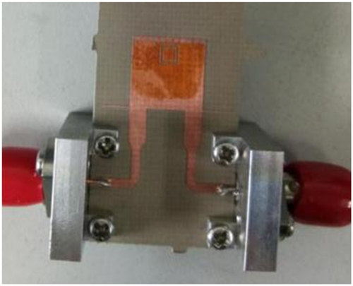
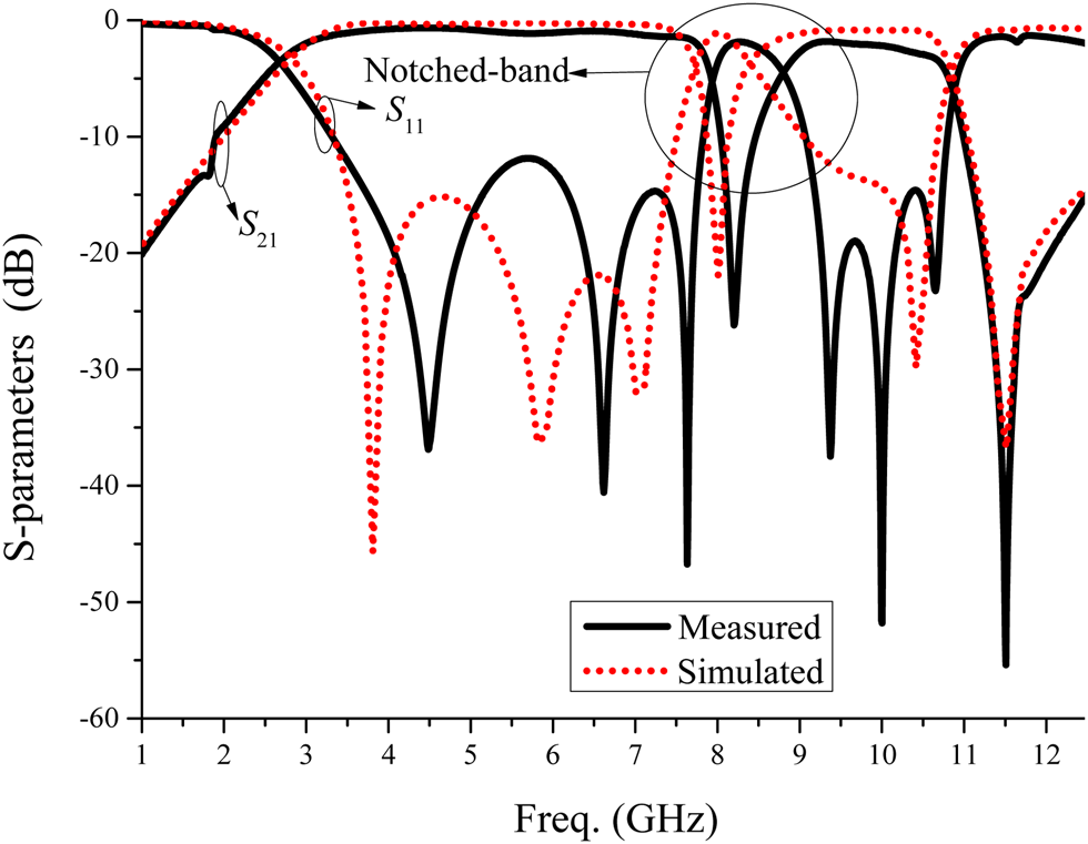
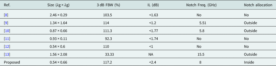
To verify, a UWB BPF with a notched band is designed, fabricated, and measured. The photograph of the fabricated filter is shown in Fig. 11. The filter is fabricated on the Taconic RF-35 substrate with a thickness of 0.508 mm, a relative dielectric constant of 3.5, and a loss tangent of 0.0018. The measured and simulated S-parameters of the proposed filter are plotted in Fig. 12, showing good consistency between them. Small discrepancies are observed owing to the tolerance of fabrication. The optimized overall geometrical dimensions are w = 9.9, l 1 = 3.85, w 1 = 0.15, l 2 = 4, w 2 = 2.34, l 3 = 1, a 1 = 2.7, c 1 = 0.2, d 1 = 0.2, b 1 = 0.2, l 0 = 1, w 0 = 1.13, d = 0.6, and s = 0.9 (all in mm). The measured frequency range is 2.75–10.53 GHz, and its 3 dB FBW is about 117.2%. The notch band centering at 8 GHz has a 3 dB FBW of 13.1%. A comparison with other reported SIW UWB filters is shown in Table 1, which demonstrates the proposed filter has good performance and smaller size.
Photograph of the fabricated filter.

Simulated and measured S-parameters of the fabricated filter.

Comparisons with previous UWB BPFs

Conclusion
A compact UWB BPF with a notched band using a perturbed quint-mode HMSIW resonator and a CSRR is presented in this paper. The resonator is developed by embedding four stubs on the end of HMSIW magnetic walls and a CSRR is introduced in HMSIW metal surface to produce a controllable notched band. The validity of the design method has been confirmed by the good simulation results and the measured results.
Acknowledgement
This work was supported in part by the Ministry of Science and Technology of the People's Republic of China under grant 2013YQ200503.
 Lili Qu received the B.S. degree from the Henan Normal University, Xinxiang, China, in 2014. She is currently pursuing the Ph.D. degree in Electromagnetics and Microwave Technology with the EHF Key Laboratory of Fundamental Science, School of Electronic Engineering, University of Electronic Science and Technology of China (UESTC), Chengdu, China. Her research interests include antennas, electromagnetic theory, and microwave circuits and systems.
 Yonghong Zhang received the B. E., M.S., and Ph.D. degrees from the University of Electronic Science and Technology of China (UESTC), Chengdu, China, in 1992, 1995, and 2001, respectively. From 1995 to 2002, he was a Lecturer with UESTC. From 2002 to 2004, he was a Post-Doctoral Fellow with the Department of Electronic Engineering, Tsinghua University, Beijing, China. Since 2004, he has rejoined UESTC. He is currently a Full Professor with the School of Electronic Engineering. He has authored or coauthored more than 100 internationally refereed journal and conference papers. He is a Senior Member of the Chinese Institute of Electronics. His research interests are in the area of microwave and millimeter-wave technology and applications.
 Qun Li received the B.S. degree in electronic information science and technology from the Southwest Petroleum University, Chengdu, China, in 2012, and the Ph.D. degree in electromagnetic field and microwave technology from the University of Electronic Science and Technology of China (UESTC), Chengdu, China, in 2018. In 2017, he joined the Department of Electrical and Computer Engineering, Wayne State University, Detroit, MI, USA, as a research scholar. From 2017 to 2018, he was a research scholar with the Department of Electrical and Computer Engineering, Rutgers University, New Brunswick, NJ, USA. His current research interests include antennas, electromagnetic theory, and microwave circuits and systems.
 Yong Fan received the B.E. degree from the Nanjing University of Science and Technology, Nanjing, China, in 1985, and the M.S. degree from the University of Electronic Science and Technology of China (UESTC), Chengdu, China, in 1992. Since 1989, he has started to do research and teaching at UESTC. He is currently a Full Professor with the School of Electronic Engineering, UESTC. He has authored or coauthored more than 200 internationally refereed journal and conference papers. He is a Senior Member of the Chinese Institute of Electronics. His main research fields include electromagnetic theory, microwave and millimeter-wave communication, millimeter-wave and Terahertz Circuits, etc. Besides, he was interested in other subjects including Broadband Wireless Access, automobile anti-collision, intelligent transportation, etc.