
I. INTRODUCTION
Organic photovoltaics represent an attractive solar energy technology, which allows fabrication of light-weight, mechanically flexible, environmentally benign, and semitransparent modules through low cost processes.Reference Søndergaard, Hösel, Angmo, Larsen-Olsen and Krebs1,Reference Youn, Park and Guo2 These advantages result from the unique characteristics of the organic semiconductors used for the photo-active layer, these being typically conjugated electron-donor polymers or small molecules in combination with electron-accepting small molecules, as soluble fullerenes, that can be deposited from solutions by printing and coating techniques (e.g., slot die and ink-jet).Reference Heeger3 Today, the most efficient organic solar cells (OSCs) have already reached power conversion efficiencies (PCEs) over 13% thereby well exceeding a 10% threshold which is considered satisfactory for mass production.4–Reference Zhao, Li, Yao, Zhang, Zhang, Yang and Hou6 This impressive development in cell performance was mainly due to significant efforts on the design of organic semiconductors, both of new donor polymers and of new nonfullerene acceptors (NFAs), exhibiting a broad solar absorption spectrum and tuned energy levels.Reference Zhao, Li, Yao, Zhang, Zhang, Yang and Hou6,Reference Li, Chang and Yang7 The recent remarkable progress of PCEs of single junction bulk heterojunction (BHJ) solar cells surpassing 13%Reference Zhao, Li, Yao, Zhang, Zhang, Yang and Hou6 was accomplished by a synergistic molecular optimization of a polymer donor and a NFA (ITIC), via fluorination, that caused higher absorption coefficients in both components and a down-shift of the molecular energy levels, such that open-circuit voltages remained high. However, although a high number of new polymers providing high PCEs were already reported, most do not meet the key requirements for the successful commercialization of OSCs—high efficiency combined with longtime stability and low-cost production. PCDTBT, a carbazole-based copolymer (poly[N-9′-heptadecanyl-2,7-carbazole-alt-5,5-(4′,7′-di-2-thienyl-2′,1′,3′-benzothiadiazole)]) (Fig. 1) is the second most investigated polymer for BHJ solar cells after poly(3-hexylthiophene) (P3HT). BHJ solar cells based on PCDTBT can reach an open-circuit voltage (V oc) of ∼0.90 V and a PCE of up to 7.5%.Reference Beaupre and Leclerc8 Peters et al.Reference Peters, Sachs-Quintana, Kastrop, Beaupré, Leclerc and McGehee9 have reported on PCDTBT:PC70BM solar cells with an estimated lifetime approaching seven years, which is the longest reported lifetime for a polymer-based solar cell, and approximately twice that of the well-studied P3HT:PC60BM system. However, in a different study, optimized P3HT:PC60BM cells cast from dichlorobenzene demonstrated much lower burn-in than cells made of blends with other less crystalline polymers, as PCDTBT.Reference Wang, Kim, Seo, Park and Park10 The higher stability of such P3HT:PC60BM cells was attributed to a three-phase morphology comprising pure fullerene domains, where charge extraction and PV efficiency are favored. Still, blends with the more amorphous polymers proved to have less fullerene dimers, which was suggested to result from a better intermixing in the polymer:PCBM blends and consequent geometrical impediments of fullerene monomers to being in close proximity and reacting.Reference Heumueller, Mateker, Distler, Fritze, Cheacharoen, Nguyen, Biele, Salvador, von Delius, Egelhaaf, McGehee and Brabec11 Other studiesReference Gasparini, Salvador, Strohm, Heumueller, Levchuk, Wadsworth, Bannock, de Mello, Egelhaaf, Baran, McCulloch and Brabec12 also reported on the suppression of burn-in in cells of P3HT upon replacing PC60BM with a NFA, IDTBR. In such a system, it was suggested that together with the absence of light-induced dimerization of the acceptor, the crystalline character of P3HT and its peculiar intermixing with IDTBR lead to a blend morphology less prone to light-induced traps and associated losses. These studies show that while the crystallinity of P3HT is relevant, and the mixing thermodynamics involved in each specific blend plays a crucial role in the stability of the cells. Nonetheless, the difference in behavior of the solar cells containing the two polymers, P3HT or PCDTBT, is attributed mainly to the semicrystalline nature of P3HT in contrast to the more amorphous nature of PCDTBT.Reference Wang, Kim, Seo, Park and Park10
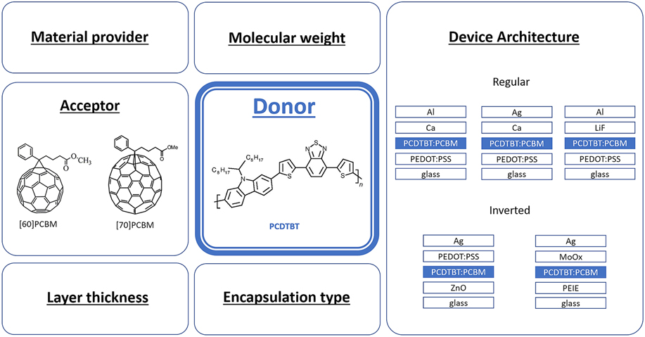
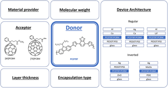
Overview of the tested device types and varied active layer parameters, along with the chemical structures of the PCDTBT donor and fullerene derivative acceptors used.

Thus, in view of the reported results on increased device stability and efficiencies, PCDTBT has been in the focus of many research groups as one of the most promising donor polymers for BHJ cells. Several different parameters have been reported to be able to influence the stability of cells based on PCDTBT. Morphological stability was determined as a key requirement for long operation of solar cells. In contrast to P3HT:PCBM-based solar cells, which require thermal annealing to achieve their highest efficiency, PCDTBT-based solar cells perform better as-cast without any heat treatment. As reported by Synooka et al.,Reference Synooka, Eberhardt, Singh, Hermann, Ecke, Ecker, von Hauff, Gobsch and Hoppe13 thermal annealing of PCDTBT:PC70BM blends above 140 °C leads to an increase of the density of defect states, which may act as carrier traps. Increasing the annealing temperature disturbs the charge carrier extraction and leads to the formation of a PCDTBT wetting layer on top of PCBM-enriched blend layer, resulting in a considerable decrease of the fill factor in standard architecture devices. Moreover, Wang et al.Reference Wang, Pearson, Dunbar, Staniec, Watters, Yi, Ryan, Jones, Iraqi and Lidzey14 found that the glass transition temperature of the PCDTBT:PCBM blend reduces upon annealing. This observation suggests that the stacking between PCDTBT conjugated chains is disrupted when the blend is heated. The reduced stacking was correlated with the reduced hole mobility measured in the thermally annealed films. According to Li et al.,Reference Li, Chiu, Shahid Ashraf, Fearn, Dattani, Cheng Wong, Tan, Wu, Cabral and Durrant15 there is a correlation between the cell architecture and the morphological stability of the BHJ blend under thermal stress. It was found that the stability of PCDTBT:PCBM solar cells under modest thermal stress is substantially increased in inverted solar cells employing ZnO substrates compared to conventional devices employing PEDOT:PSS-covered substrates. Improved lifetime of devices, in addition to improved environmental stability against ambient humidity exposure, was correlated with suppression of micro- and nanoscale morphological degradation by decreased crystallization of PCBM on ZnO as compared to PEDOT:PSS.
In addition to morphological instabilities arising from the presence of the fullerene acceptor, the influence of the PCDTBT properties have also been investigated. The effect of the PCDTBT molecular weight on the performance of OSCs has been investigated,Reference Kingsley, Marchisio, Yi, Iraqi, Kinane, Langridge, Thompson, Cadby, Pearson, Lidzey, Jones and Parnell16,Reference Katsouras, Gasparini, Koulogiannis, Spanos, Ameri, Brabec, Chochos and Avgeropoulos17 and the resultsReference Katsouras, Gasparini, Koulogiannis, Spanos, Ameri, Brabec, Chochos and Avgeropoulos17 revealed that higher molecular weights are beneficial for the device performance up to a limiting point, where the polymer solubility causes a reduction of the PCDTBT concentration in the active layer.Reference Kingsley, Marchisio, Yi, Iraqi, Kinane, Langridge, Thompson, Cadby, Pearson, Lidzey, Jones and Parnell16 The acceptor material also plays a significant role, both in device performance and long-term stability.Reference Cheng, Yan, Wu, Wang, Qin, An, Cao, Huo, Zhang, Ding, Sun, Ma and Zhan18 Beaupré and LeclercReference Beaupre and Leclerc8 reported that the preferred acceptor for PCDTBT-based BHJ solar cells is PC70BM, given its broader visible light absorption spectrum as compared to PC60BM. Moreover, according to Mateker et al.,Reference Mateker, Sachs-Quintana, Burkhard, Cheacharoen and McGehee19 the stronger tendency of PC60BM to photodimerization, which detriments the morphological stability and the lifetime of BHJ solar cells, makes it a less suitable acceptor in comparison with PC70BM.
Another factor affecting the morphological stability of BHJ cells was found to be the solvent used for the photoactive blend deposition.Reference Alem, Chu, Tse, Wakim, Lu, Movileanu, Tao, Bélanger, Désilets, Beaupré, Leclerc, Rodman, Waller and Gaudiana20–Reference Ciammaruchi, Brunetti and Visoly-Fisher22 Alem et al.Reference Alem, Chu, Tse, Wakim, Lu, Movileanu, Tao, Bélanger, Désilets, Beaupré, Leclerc, Rodman, Waller and Gaudiana20 have demonstrated that PCDTBT:PC70BM films prepared with chloroform (CF) exhibit larger domains than those prepared with 1,2-dichlorobenzene (DCB). Fine tuning of the domain size was achieved by using a mixed solvent of CF and DCB. In another report from Fang et al.,Reference Fang, Liu, Fu, Meng, Zhang, Xie and Wang23 it was shown that a clearly defined nanoscale phase separation within the PCDTBT:PC70BM blend can be obtained when a 1,2,4-trichlorobenzene:CF mixture is used as the solvent. The resulting morphology is similar to that produced with pure DCB.
Apart from morphological changes, the photoactive layer can suffer from photochemical reactions, photocatalytic processes, and impurity inclusions, such as the metal ions diffusing from the electrodes.Reference Peters, Sachs-Quintana, Mateker, Heumueller, Rivnay, Noriega, Beiley, Hoke, Salleo and McGehee24 Photoinduced reactions in the active layer leading to the formation of sub-bandgap states are considered to be the main cause of the so-called “burn-in” effect.Reference Peters, Sachs-Quintana, Mateker, Heumueller, Rivnay, Noriega, Beiley, Hoke, Salleo and McGehee24 An important aspect of the aging process during burn-in is that it starts rapidly but then it slows down and appears to stop, suggesting that the reactive species might have been depleted. Kong et al.Reference Kong, Song, Yoo, Lee, Kwon, Park, Back, Kim, Lee, Suh and Lee25 have demonstrated long-term stable polymer solar cells with significantly reduced burn-in loss. By isolating trap-embedded components from the pristine photoactive polymers based on the unimodality of molecular weight distributions, the authors were able to selectively extract a trap-free, high-molecular-weight component. The resulting polymer component exhibited enhanced PCE and long-term stability without the initial abrupt burn-in degradation.
Besides the number of processes which undergo in the photoactive layer, the degradation of OSCs can also occur at the electrodes.Reference Peters, Sachs-Quintana, Mateker, Heumueller, Rivnay, Noriega, Beiley, Hoke, Salleo and McGehee24,Reference Roesch, Eberhardt, Engmann, Gobsch and Hoppe26 Especially low work function metals, like aluminum as the electron extracting contact, and their interfaces with the photoactive layer were found to be very unstable due to oxidation and delamination, even under superior sealing conditions.Reference Roesch, Eberhardt, Engmann, Gobsch and Hoppe26 To overcome this issue, Roesch et al.Reference Roesch, Eberhardt, Engmann, Gobsch and Hoppe26 have incorporated a solution-processed titanium oxide interlayer between the photoactive layer and the electron transporting metal. A TiO2/Al bilayer as the electron extracting contact appeared to be very stable, exhibiting ∼100 h of lifetime without any sealing and approximately 18,000 h of extrapolated operation time with superior glass–glass sealing.
Finally, encapsulation is a valuable method to enhance the long-term stability of the devices. A long operational device life-time was extrapolated from a stability study performed inside of a glovebox,Reference Peters, Sachs-Quintana, Kastrop, Beaupré, Leclerc and McGehee9 while a one-year study of devices operating under standard working conditions revealed that degradation of the solar cells is a result of edge-ingress of water or moisture through the encapsulation.Reference Zhang, Bovill, Kingsley, Buckley, Yi, Iraqi, Wang and Lidzey27 The water ingress will greatly depend on the diffusion coefficient of the device stack materials, e.g., devices based on PEDOT:PSS are particularly susceptible to moisture, mainly because of its large water diffusion coefficient.Reference Adams, Salvador, Lucera, Langner, Spyropoulos, Fecher, Voigt, Dowland, Osvet, Egelhaaf and Brabec28
With a number of reports on the stability of BHJ solar cells based on PCDTBT at hand,Reference Turkovic, Engmann, Egbe, Himmerlich, Krischok, Gobsch and Hoppe29,Reference Voroshazi, Cardinaletti, Conard and Rand30 we here combine the efforts of a high number of researchers working in the field of OSCs and PCDTBT materials, in particular, to jointly identify the most critical parameters influencing the stability of PCDTBT-based BHJ solar cells. Using data and sample exchange, we were able to investigate and compare a large number of devices that were stressed in aging tests using identical conditions for all types of devices. The results from this interlaboratory study allowed us to outline several general conclusions related to PCDTBT-based BHJ solar cells and specific observations related to the different device architectures and fabrication/encapsulation procedures used. Noteworthy, the study helped each involved group to make a self-critical look onto the device manufacturing process and facilitated the development of state-of-the-art devices. The results herein reported can be considered as a practical guidance for the realization of stabilization approaches in BHJ solar cells containing PCDTBT.
II. EXPERIMENTAL
The research laboratories participating in this study each have produced at least 10 identical devices, which have been encapsulated and shipped to the partners for aging and characterization. The main idea was that BHJ solar cells should be based on the PCDTBT absorber, whereas other parameters such as the type of charge transport layer (CTL), solar cell architecture, encapsulation type, etc. were varied depending on the laboratories (Fig. 1). In this way, the device producers used the architectures and materials in which they already had a solid experience. This guaranteed high efficiency and reproducibility of the devices, thus giving a high level of credibility to the performed research. Vice versa, asking device producers to use identical device architecture and materials might have given a lower level of credibility, as these architectures and materials would have been new for the laboratories and in lack of time-extensive process, optimization might have resulted in suboptimal devices.
Thus, seven research laboratories produced 10 identical devices each. With the aim of keeping objectivity, the names of producers are kept anonymous, and the devices will be referred to as Type 1, Type 2, …, Type 7. The layer structure consists of anode/CTL/PCDTBT:PCBM/CTL/cathode, as detailed in Table S1 (see the Supplementary Material). Five device structures in this study have a “standard” layout (Types 1, 3, 5, 6, and 7), and two have an “inverted” one (Types 2 and 4). Devices are fabricated on top of ITO-covered glass and are encapsulated using different methods (see Table S1 in the Supplementary Material). The area of the devices ranged between 4 mm2 and 3.75 cm2. The typical PCE values of each device type are shown in Fig. S1 (see the Supplementary Material).
Standard cells use ITO as anode and PEDOT:PSS as the hole transport layer (HTL). Regarding electron transport layer (ETL) and cathode, Types 1, 3, and 6 use Ca/Al, Type 5 uses LiF/Al, and Type 7 uses Ca/Ag. Inverted structures use ITO as cathode and ZnO (Type 2) or PEIE (Type 4) as the electron extraction layer (EEL). The anode is Ag and HTL is PEDOT:PSS (Type 2) or MoO3 (Type 4).
After standard cleaning and drying processes, the substrates were treated with UV-oxygen plasma for several minutes (from 3 to 20 min). In standard devices, PEDOT:PSS was spin-coated and thermally annealed for several minutes over 100 °C to remove any residual water. Next, the blend PCDTBT:PCBM prepared in chlorobenzene or dichlorobenzene was spin-coated on top of the PEDOT:PSS. Details of the blend ratio, concentration, and deposition parameters are given in Table S2 (see the Supplementary Material). The ETL (Ca or LiF) and cathode (Al or Ag) were thermally evaporated in high vacuum. In inverted devices, the EEL was spin-coated (PEIE or ZnO) on top of the ITO. The blend is then spin-coated and dried. In Type 2, PEDOT:PSS is spin-coated on top of the blend and annealed for 10 min at 120 °C. The cathode was always thermally evaporated. In Type 4, both MoO3 and Ag cathodes were thermally evaporated on top of the blend.
The number of cells available for testing varied from one PCDTBT producer to another, due to some accidental cell breakdown, but at least two identical devices per producer were tested for each aging protocol. We note here that it was not possible to realize complete tests on Type 1 and Type 7, due to their sudden failure/breakdown during the series of testing. Therefore, Type 1 will not appear in the results and will not be discussed any further, while Type 7 will only appear in two of the aging protocols performed.
The devices were aged according to 4 different protocolsReference Reese, Gevorgyan, Jørgensen, Bundgaard, Kurtz, Ginley, Olson, Lloyd, Morvillo, Katz, Elschner, Haillant, Currier, Shrotriya, Hermenau, Riede, Kirov, Trimmel, Rath, Inganäs, Zhang, Andersson, Tvingstedt, Lira-Cantu, Laird, McGuiness, Gowrisanker, Pannone, Xiao, Hauch, Steim, DeLongchamp, Rösch, Hoppe, Espinosa, Urbina, Yaman-Uzunoglu, Bonekamp, van Breemen, Girotto, Voroshazi and Krebs31:
(i) ISOS-D1: laboratory weathering in the dark at ambient temperature (shelf lifetime);
(ii) ISOS-L1: laboratory weathering under simulated illumination at ambient temperature;
(iii) ISOS-L2: laboratory weathering under simulated illumination and elevated temperature (65 °C);
(iv) Daylight outdoor weathering under sunlight with measurements under simulated illumination.
All devices were initially characterized at the aging laboratories before starting the actual degradations, and time = 0 was defined as the starting point of each test. Devices characterized according to the ISOS-D1 protocol were stored in the dark and monitored weekly for the first 12 weeks, and thereafter with the characterization sequence of 5, 4, and 7 weeks. The I–V measurements were performed under AM1.5G illumination by using a solar simulator equipped with a xenon lamp and the Keithley 2400 source meter (Tektronix, Cleveland, Ohio). The aging following ISOS-L1 and ISOS-L2 protocols were prepared with a home-built stability setup enabling periodic in situ I–V characterization. The setup consists of ATLAS KHS 1200 W solar simulator (ATLAS, Linsengericht, Germany), under which solar cells can be placed and connected to a computer-controlled source-measure unit. The automatic periodic I–V characterization was implemented by multiplexing. For the daylight outdoor degradation experiment, the cells were mounted on a 30° tilted rack from the horizontal. The intensity was measured with a calibrated thermopile pyranometer (Eppley PSP, The Eppley Laboratory Inc., Newport, Rhode Island) set to the same angle as the cells. This protocol differs from the ISOS-O1 protocol only by the fact that the cells were exposed to sunlight only during daylight (i.e., 6 h per day) until their T 80 was reached, amounting to a total exposure time of ∼120 h, between February 14th and March 30th 2016. The cells were measured with a solar simulator (AM1.5 class AAA Newport Oriel Verasol LSH-7520 solar simulator, Newport Corporation, Irvine, California) and a Keithley 2410 sourcemeter (Tektronix, Cleveland, Ohio). Between the light hours, the cells were stored in the dark in shelf life conditions. This was done to inhibit humidity-related breach/contact oxidation problems during the night. It is noteworthy to mention that the spectrum measured at noon time ±2–3 h of a cloudless day at Sede Boker (the Negev desert, Israel, Lat. 30.8°N, Lon. 34.8°E, Alt. 475 m) is nearly identical to the AM 1.5G spectrum. The details of similar outdoor degradation experiment are described elsewhere.Reference Kettle, Bristow, Gethin, Tehrani, Moudam, Li, Katz, dos Reis Benatto and Krebs32,Reference Burlingame, Zanotti, Ciammaruchi, Katz and Forrest33 Devices under the same condition were stressed side-by-side. All devices were aged at V oc.
The devices aged following the ISOS-L1 and ISOS-L2 protocols were characterized before and after aging using photoluminescence imaging (PLI). The luminescence imaging is based on the detection of luminescent radiation from a solar cell with a camera. Here, a silicon charge coupled device camera (Si-CCD, ANDOR iKon-M, Andor Technology Ltd., Belfast, U.K.) was used during PLI, and the devices were excited with a blue solid-state diode array emitting at 470 nm, leading to efficient photon absorption and exciton formation within the PCDTBT with subsequent radiative decay. To block the excitation light of the LED array, a cutoff filter was placed in front of the Si-CCD. As the overall luminescence intensities are relatively small, the whole setup was placed into a light blocking housing.
A. Analysis of the experimental results
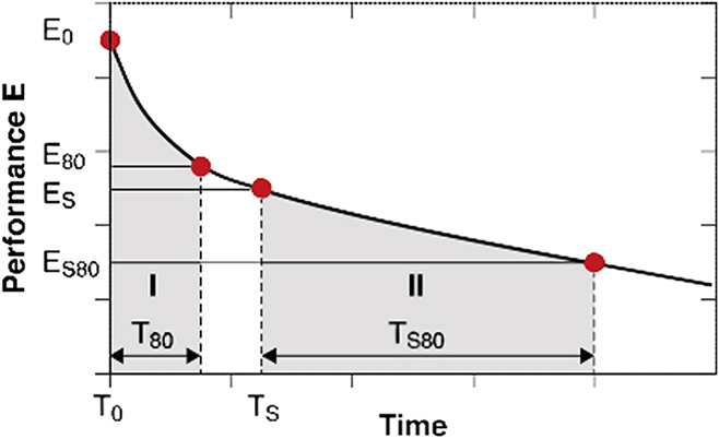
Figure 2 collects the main parameters defined as lifetime markers of a solar cell, as reported earlier.Reference Gevorgyan, Espinosa, Ciammaruchi, Roth, Livi, Tsopanidis, Zufle, Queiros, Gregori, Benatto, Corazza, Madsen, Hosel, Beliatis, Larsen-Olsen, Pastorelli, Castro, Mingorance, Lenzi, Fluhr, Roesch, Ramos, Savva, Hoppe, Marques, Burgues, Georgiou, Serrano-Lujan and Krebs34 T 80 is commonly defined as the time when the device is degraded by 20% from the initial efficiency PCE(T 0). T s is the starting time of the more stabilized portion of the efficiency curve, while T s80 is the time when the efficiency reaches 80% of its stabilized value [80% of PCE(T s)], as shown in Fig. 2. All solar cell parameters shown in this paper are normalized with respect to their value at T 0.
Lifetime curve defined with the characteristic parameters. Reproduced with permission from Wiley-VCH.Reference Gevorgyan, Madsen, Roth, Corazza, Hösel, Søndergaard, Jørgensen and Krebs35

The efficiency curves were fitted with either a one-phase (ISOS D1 conditions) or two-phase (ISOS L1, L2, and O1 conditions) exponential decay function. For devices with slower decay dynamics, when the T s80 was not reached within the duration of the measurements, the lifetime markers were extrapolated from the available data points. Within the same aging test and for devices comprising more than one pixel, single figures of merit (f.o.m.) were measured for each pixel and then averaged for all identical pixels per each time point. Generally, standard deviations obtained for Type 5 and Type 6 devices are the widest, with a tendency to increase even more over the time, which we attribute to the poorer encapsulation in those device types. In these cases, the upper edge corresponds to the most stable device of this type and the lower edge corresponds to less stable device.
III. RESULTS AND DISCUSSION
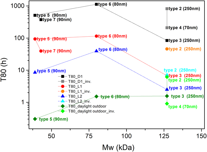
Figure 3 shows the T 80 behavior of the tested device as a function of the molecular weight of the PCDTBT. Despite the absence of some data points due to the mechanical breakdown of devices, the plot reveals some interesting relationships between the properties of the donor molecule and the lifetimes of the devices. The general outcome is that the time in which the devices reach their T 80 point is strongly dependent on the aging condition, and it is in the order T 80(D1) > T 80(L1) > T 80(L2) > T 80(daylight outdoor). This is true for all tested device types—inverted and standard architecture—and regardless of the molecular weight of the polymer or the type of interlayers implemented.
T 80 parameter of devices (inverted architecture is named “inv.”) degraded under different stress conditions, correlated with molecular weight of the PCDTBT. Degradation conditions are denoted as follows: square for ISOS D1, circle for ISOS L1, triangle for ISOS L2, and rhombus for daylight outdoor weathering.

It has been demonstrated that the molecular weight of specific donor polymers has an important impact on the morphology and polymer ordering (π-stacking) of OSC devices,Reference Gevorgyan, Madsen, Roth, Corazza, Hösel, Søndergaard, Jørgensen and Krebs35–Reference Kline, McGehee, Kadnikova, Liu, Frechet and Toney40 but also on the stability of the cells.Reference Ding, Kettle, Horie, Chang, Smith, Shames and Katz41 Ding et al.Reference Ding, Kettle, Horie, Chang, Smith, Shames and Katz41 showed that solar cells based on PTB7 with higher molecular weight were more stable over time and exhibited better operational stability. Using EPR spectroscopy, it was found that the higher molecular weight polymer samples contained a lower density of radical species in the material. As shown by Troshin et al., such radical species might act as deep traps for mobile charge carriers, therefore diminishing the electrical performance of the cells.Reference Frolova, Piven, Susarova, Akkuratov, Babenko and Troshin42–Reference Shames, Inasaridze, Akkuratov, Goryachev, Katz and Troshin44 In Fig. 3, it is also seen that increasing the molecular weight from 39 to 80 kDa, while maintaining the same active layer thickness, appeared beneficial for the device stability, as manifested by a longer T 80 time. It should also be noted that this result is obtained despite the calcium-based cathodes used in Type 6, which is known to be a particularly unstable contact material.Reference Glen, Scarratt, Yi, Iraqi, Wang, Kingsley, Buckley, Lidzey and Donald45–Reference Glen, Scarratt, Yi, Iraqi, Wang, Kingsley, Buckley, Lidzey and Donald49 When increasing the molecular weights to 127 kDa, however, devices having the same standard architecture (Type 3) show a drop-in device stability. We attribute this behavior to the thicker Ca layer used in the Type 3 cells. Moreover, Type 3 cells have thicker active layers, which could have an impact on the device stability as well. Therefore, there seems to be an interconnection between Mw and cell T 80 up to a certain threshold value, after which the excessively high molecular weight may affect the device stability. When comparing standard versus inverted device architectures for molecular weights of 127 kDa, it is clear that the inverted cells outperform the standard configuration devices, as it has also been demonstrated for many other material systems in OSCs.Reference Mateker, Sachs-Quintana, Burkhard, Cheacharoen and McGehee19,Reference Lloyd, Olson, Lu, Fang, Moore, White, Reese, Ginley and Hsu50 Such improved stability is mainly due to the use of high work function cathodes. We point out here that the T 80 parameter utilized for our analysis does not reflect the overall device reliability but is rather one of the typical indicators for looking at certain initial dynamics related to OPV stability. Nevertheless, even by looking at the stabilized time of the devices against Mw (Fig. S2 in the Supplementary Material), we do find a similar—even if less defined—trend, where a [T s–Mw] optimum seems to be recognizable. Therefore, we feel confident in correlating the Mw to the “rate of degradation” (T 80 versus Mw), but also to the time the device gets to a stabilized value of efficiency (T s versus Mw), after which the degradation process proceeds on a much slower pace.
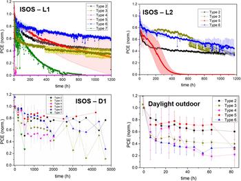
In Fig. 4, the PCEs of different device types and aging protocols are plotted as a function of time. Unfortunately, device failures are found for some of the investigated cells. This is seen for example at a very early stage for the Type 4 cell under ISOS-L1 conditions and for Type 5 at later stages under ISOS-L2 conditions. We ascribe these failures to mechanical breaks of the encapsulation during the experiments.
Comparison of long-term PCEs of the different types of devices measured under the four degradation conditions.

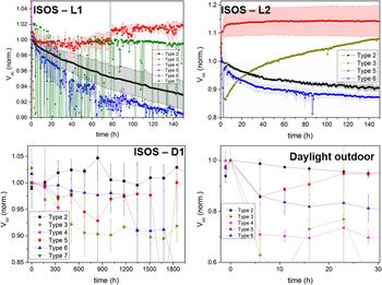
In the following sections, detailed performance comparisons for the different ISOS degradation conditions will be given. First of all, we note that in some cases, small increases in PCE are seen at the beginning of degradation, which result from an increase in V oc. To emphasize this, in Fig. 5, we plot V oc as a function of time for the different ISOS degradation conditions. The small increase is seen for Type 5 devices under all degradation conditions and for Type 3 devices under the ISOS-L2 conditions. Such an increase in V oc has also been observed in previous OSC stability investigations, and it was found to be the result of cathode oxidation, as in contact with air, a thin oxide layer can be formed at the cathode interface, minimizing interface recombination effects,Reference Karst and Bernède51,Reference Lloyd, Peters, Garcia, Kauvar, Berry, Reese, McGehee, Ginley and Olson52 which could also explain the observed effects for the specific cases mentioned here.
Comparison of long-term open circuit voltages of the different types of devices measured under the four degradation conditions (only the initial 0–100 h are represented).

A. D1—degradation
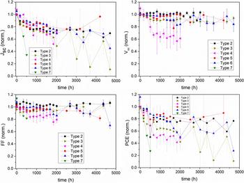
The ISOS-D1 conditions resulted (see Fig. 6) in the longest lasting degradations, with all but one PCE best fit displaying a single exponential decay with time constants given in Table S1 (see the Supplementary Material). The PCE trends were mainly dictated by the J sc, and the single time constant parameter could indicate one major degradation process affecting the cells, even though at a very low rate. In this respect, the edge-ingress of water and moisture through the encapsulation system has already been reported as the principal factor responsible for the performance drop of cells under similar conditions.Reference Tanenbaum, Dam, Roesch, Jorgensen, Hoppe and Krebs53,Reference Zhang, Bovill, Kingsley, Buckley, Yi, Iraqi, Wang and Lidzey54 We may speculate that for these degradation conditions, intrinsic differences in the polymer, like molecular weight, morphology, or solubility limits, are of less importance with respect to the extrinsic mechanisms (permeable encapsulation) responsible for the PCE drop. As ISOS-D1 is the mildest degradation condition experienced by the cells, we attribute the fast (∼500 h) PCE drop of Type 7 to the defective or insufficient encapsulation adopted, which proved to be inadequate also under the other aging conditions.
Solar cell parameters of the different device types measured under ISOS D1 conditions (in the dark at room temperature).

B. L1—light-soaking indoor
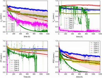
The ISOS-L1 testing was performed indoors, under constant 1 Sun light-soaking and ambient temperature and humidity, and due to the heat from the simulated light, the temperature of the devices was 45 °C. As expected (see Fig. 7), all the long-term PCE curves show a pronounced initial drop due to the light-activated burn-in reactions.Reference Peters, Sachs-Quintana, Mateker, Heumueller, Rivnay, Noriega, Beiley, Hoke, Salleo and McGehee24,Reference Voroshazi, Cardinaletti, Conard and Rand30,Reference Tournebize, Bussiere, Wong-Wah-Chung, Therias, Rivaton, Gardette, Beaupre and Leclerc55–Reference Inasaridze, Shames, Martynov, Li, Mumyatov, Susarova, Katz and Troshin57 The efficiency decrease seems mostly dominated by J sc, and less by V oc and FF, which are mainly dropping in the burn-in period and are otherwise stable.
Solar cell parameters of the different device types measured under ISOS L1 conditions (1 Sun illumination at room temperature).

The photo-oxidation processes taking place in PCDTBT is governed by combined chain-scission and cross-linking reactions. The process starts by chain-scission of the C–N bond between the carbazole group and the tertiary carbon atom, bearing the alkyl side chain,Reference Tournebize, Bussiere, Wong-Wah-Chung, Therias, Rivaton, Gardette, Beaupre and Leclerc55 followed by cross-linking between the carbazole unit and the fullerene acceptor.Reference Tournebize, Rivaton, Gardette, Lombard, Pepin-Donat, Beaupre and Leclerc56 Based on EPR spectroscopy measurements, it has been demonstrated that the burn-in period is correlated with these cross-linking reactions and with the formation of defects along the polymer chain.Reference Tournebize, Rivaton, Gardette, Lombard, Pepin-Donat, Beaupre and Leclerc56 Following the burn-in, the modified system enters a more stable phase with minimum degradation over time.
Comparing again Type 5 and Type 6 devices which possess comparable active layer thicknesses but different molecular weights, it seems that Type 6 devices with a molecular weight of 80 kDa are experiencing a much weaker burn-in than Type 5 devices with a molecular weight of 39 kDa. Since radical defects can be expected to be present mostly on the polymer chain ends, the larger molecular weight would imply having less radical defects.Reference Ding, Kettle, Horie, Chang, Smith, Shames and Katz41 Thus, one can speculate that the described chain-scission and cross-linking processes will be dependent on the molecular weight of the polymer, and that more pronounced chain-scission and cross-linking processes will take place in the lower molecular weight polymer as it has a higher density of radical defects. That would explain the small burn-in for Type 6 devices, experiencing a very slow J sc decrease over the whole aging period. As mentioned earlier, the influence from the thick calcium-based cathode in Type 3 devices could overshadow the contribution of the larger molecular weight donor in this device type.
C. L2—light-soaking indoor @ 65 °C
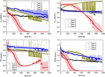
Besides the V oc effect, which was commented on earlier, it is clear from the ISOS-L2 testing (see Fig. 8) that under increased heat, the cell degradation further accelerates compared to the ISOS-L1 tests. Indeed, high temperature proves to be a detrimental factor for PCDTBT-based solar cells.Reference Synooka, Eberhardt, Singh, Hermann, Ecke, Ecker, von Hauff, Gobsch and Hoppe13 Interestingly, we see in the ISOS-L2 stability tests that the long-term stability of the inverted cells, Type 2, is worse than for some of the devices with the standard configuration. It is known that the PCDTBT:PCBM morphology is more stable when comprising ZnO layers as compared to PEDOT:PSS layers,Reference Li, Chiu, Ashraf, Fearn, Dattani, Wong, Tan, Wu, Cabral and Durrant58 which cannot explain this observed effect. In addition, the large molecular weight of the polymer used in the inverted cells should also lead to the lower radical defect density and thus improved device stability.Reference Ding, Kettle, Horie, Chang, Smith, Shames and Katz41 Also, employing PC70BM as the acceptor should lead to more stable cells as compared to PC60BM, which also does not correlate with the inverted cells investigated in this study.Reference Li, Chiu, Ashraf, Fearn, Dattani, Wong, Tan, Wu, Cabral and Durrant58 In fact, comparing the inverted device stack investigated here with a similar one from the literature possessing high device stability,Reference Tournebize, Bussiere, Wong-Wah-Chung, Therias, Rivaton, Gardette, Beaupre and Leclerc55 the only difference is that the HTL used here is PEDOT:PSS instead of MoOx, therefore we speculate that PEDOT:PSS could be the main reason for the observed device instabilities seen for the inverted cell here.Reference Lloyd, Peters, Garcia, Kauvar, Berry, Reese, McGehee, Ginley and Olson52,Reference Voroshazi, Verreet, Buri, Mueller, Di Nuzzo and Heremans59
Solar cell parameters of the different device types measured under ISOS L2 conditions (1 Sun illumination at 65 °C).

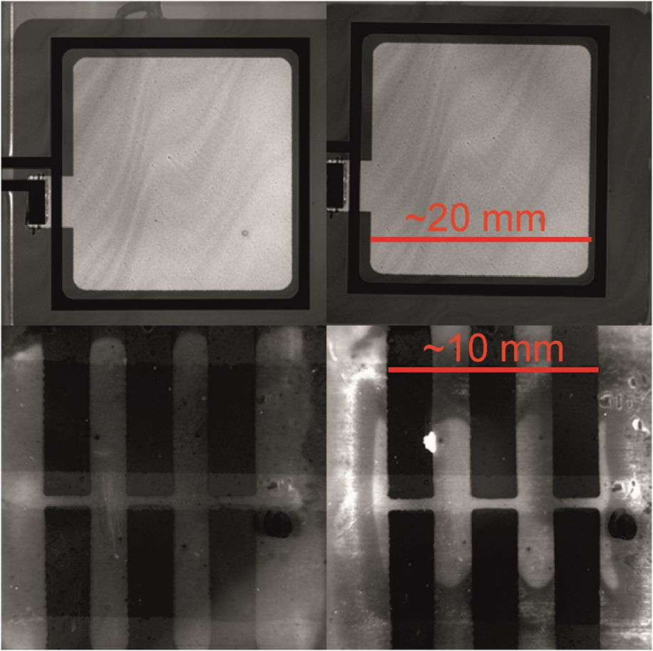
For all devices undergoing this specific ISOS-L2 aging test, the periodic I–V characterization was complemented with pre- and post-aging PLI. In most cases, PLI revealed no luminescence changes due to side ingress of water or oxygen; thus for the majority of devices investigated here, only intrinsic degradation processes need to be considered. As an example, the PLI images for a Type 2 device before and after aging are shown in the upper row of Fig. 9. Only a slight decrease in the overall intensity coming from the active layer can be detected. This can be attributed to the very slight, homogeneous degradation of the photoactive layer. In contrast to that, Type 4 devices showed severe side ingress, presumably of water and oxygen from the ambient air (compare with the lower row of Fig. 9). Along the edges of the back contact of the solar cell (six dark stripes), a contrast change can be detected: the outer, presumably degraded parts appear darker in between those contacts, while to the center of the sample luminescence yields a brighter and thus more intense signal, indicating the nondegraded portion of the active layer. This finding is in good agreement with the already reported fast degradation of the Type 4 devices under L1 and L2 aging conditions and provides an explanation for that: photo-oxidation of the active layer and possibly further degradation processes at charge extraction layers.
Photoluminescence images of Type 2 devices (upper row) and Type 4 devices (lower row) of fresh (left column) and aged (right column) samples. The aging was done under ISOS L2 conditions for 1200 h. The scale bar for PL intensity of the upper two images is exactly the same, while the scale for the lower two images is very comparable.

D. Daylight outdoor light-soaking
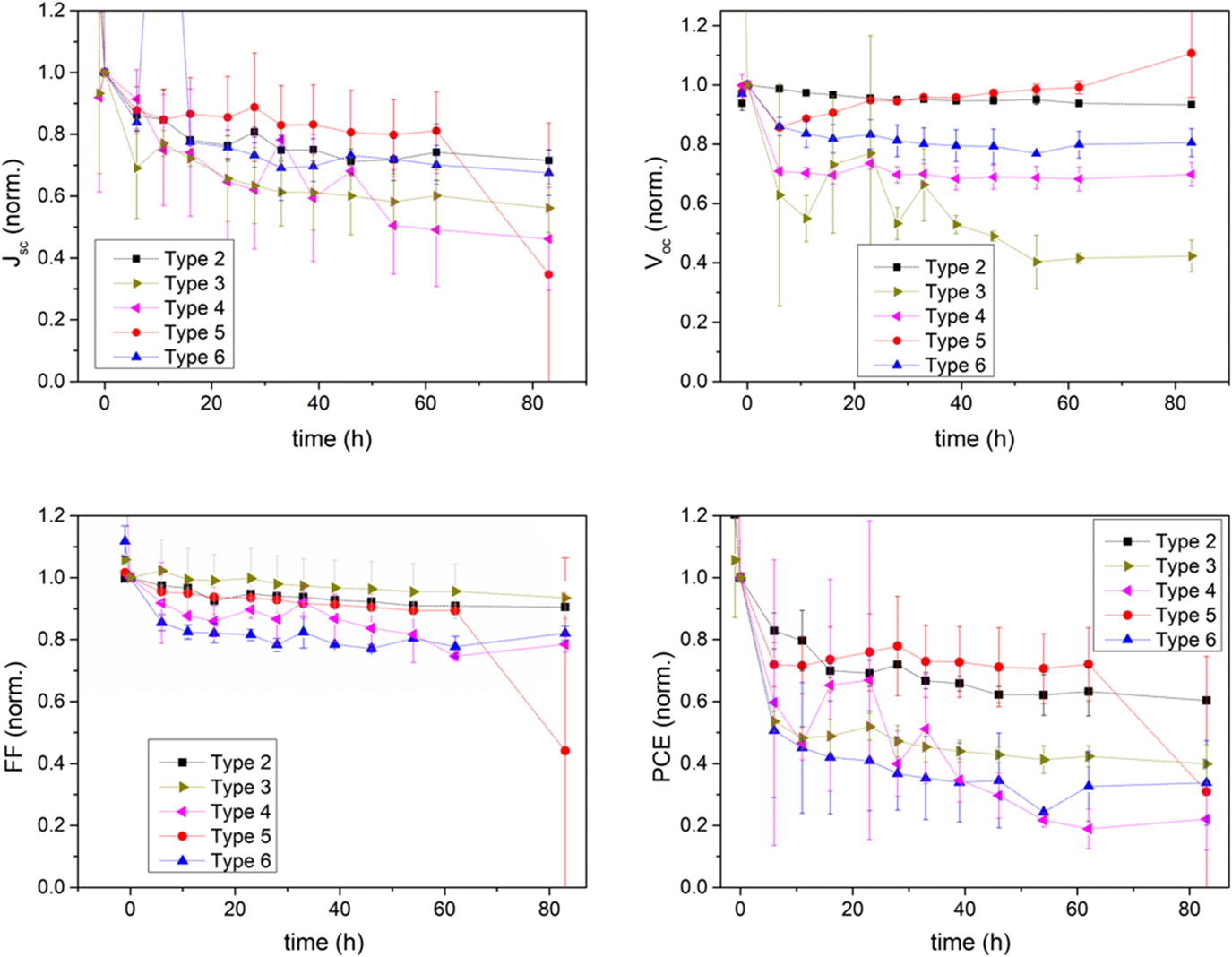
For the outdoor stability tests, degradation of J sc dominates the PCE for all the investigated device types (Fig. 10). The burn-in period is in all cases followed by a more linear behavior, and it is on average less than 10 h long. Comparing the different aging conditions, the outdoor tests clearly lead to the fastest degradation of the cells, which suggests that external effects are dominating the degradation process. Therefore, comparing molecular weights, morphology, and even electrode interlayers and device configurations may lead to the wrong conclusions. Here, we point to the device encapsulation as one of the key factors for the observed outdoor stability effects. Thus special care should be given to the implementation of ultra-low moisture permeation encapsulation with effective oxygen and humidity barriers,Reference Nair, Kathiresan, Mukundan and Natarajan60–Reference Cheng and Zhan66 as well as to the addition of stabilizing compounds that may alleviate the rapid degradation arising from the presence of reactive radical species.Reference Salvador, Gasparini, Perea, Paleti, Distler, Inasaridze, Troshin, Luer, Egelhaaf and Brabec67–Reference Turkovic, Engmann, Tsierkezos, Hoppe, Madsen, Rubahn, Ritter and Gobsch70
Solar cell parameters of the different device types measured under ISOS daylight outdoor weathering.

IV. CONCLUSIONS
In conclusion, we have shown that multiple effects should be considered when comparing the device stability of PCDTBT-based solar cells. Although the lifetimes presented here still do not always meet the stringent industry standards as required for product commercialization—mostly due to a limited optimization steps which can be conducted at science laboratories as compared to the extensive optimization procedures standardly applied by the industry, this study allowed us to extract useful correlations between materials, technological solutions, degradation protocols, and PV performance and perform a thorough analysis of such solar cell devices. First and foremost, a proper device encapsulation—at times lacking in the devices presented here—appears mandatory to ensure the potentially high lifetime of the PCDTBT-based devices. In addition, the vast laboratory cross-comparison sheds some light on the most suitable combinations out of the wide variety of available interlayer materials, to point toward a finer device optimization. The device architecture and choice of interlayers strongly affect the long-term device performance, and their impact on the device stability is strongly correlated with the aging conditions used. The implemented interlayers should always be carefully chosen also on the basis of their stability, as well as the final device application. In general, a Ca-based electrode proved to contribute to an early failure of the device, likely due to its instability toward moisture and water, therefore other top contacts should be preferred. As well, ZnO-based cells performed better than those comprising PEDOT:PSS, especially under ISOS-L2 aging protocol. This could provide an indication for material selection, once certain specific applications for OPV have been targeted.
On the other hand, despite differences originating from these factors, which are not directly related to the active layer materials, some conclusions on the physical properties of the PCDTBT polymer could also be made. The molecular weight seems to be a significant factor for determining both the cell burn-in time and the time of stabilization (T s), as the radical defect density is expected to be inversely proportional to the molecular weight, and as such found to dictate the trend of the initial degradation process to a significant extent. An optimum combination of molecular weight and active layer thickness appears to exist in terms of achieving the longest T 80 period, regardless of the ISOS degradation protocol used.
We expect that the observations made in this study on the physical properties of the materials as well as on the importance of the choice of optimal interlayer materials and cell architectures will contribute to the enhancement of the stabilities of organic solar devices developed in the future, both those employing the materials tested in the study, but also applied to those comprising novel materials and employing innovative fabrication methods, such as for example NFAs and more stable encapsulation formulations similar to those currently used for the commercialized OLED devices.
Supplementary Material
To view supplementary material for this article, please visit https://doi.org/10.1557/jmr.2018.163.
ACKNOWLEDGMENTS
This work was supported by the European Commission’s StableNextSol COST Action MP1307.
(1) Sjoerd Veenstra, Santhosh Shanmugam, and Yulia Galagan acknowledge Solliance, a partnership of R&D organizations from the Netherlands, Belgium, and Germany working in thin film photovoltaic solar energy.
(2) Ana Charas acknowledges Fundação para a Ciência e Tecnologia (FCT-Portugal) for funding through the project UID/EEA/50008/2013.
(3) Vida Turkovic, Horst-Günter Rubahn, and Morten Madsen acknowledge ‘Det Frie Forskningsråd DFF FTP’ for funding of the project Stabil-O and Villum Foundation for funding of the project Compliant-PV, Project No. 13365.
(4) Gloria Zanotti is thankful to the Ente Nazionale Energia e Ambiente (ENEA) and to the Italian Ministry of Foreign Affairs for a visitor post-doc fellowship to Ben Gurion University of the Negev.
(5) Tulus acknowledges the Ministry of Research, Technology and High Education, the Republic of Indonesia (RISET-Pro Scholarship). Tulus and Elizabeth von Hauff acknowledge Fundamental Research on Matter (FOM) (V0714M-13MV60) from the Netherlands Organization for Scientific Research (NWO) for funding.
(6) Rickard Hansson and Ellen Moons thank Dr. Jakub Rysz of the Institute of Physics, Jagiellonian University, for sharing device preparation details and also acknowledge financial support from the Swedish Research Council, Grant No. 2015-03778, the Swedish Energy Council, Contract No. 38327-1, and the Göran Gustafsson Foundation for Research in Natural Sciences and Medicine.
(7) L.F. Marsal, J. Ferre-Borrull, and J.G. Sánchez thank the Spanish Ministry of Economy, Industry and Competitiveness (MEIC) for grant numbers, TEC2015-71915-REDT and TEC2015-71324-R (MINECO/FEDER), the ICREA for the ICREA Academia Award, and the Catalan authority for project AGAUR 2017 SGR 1527.
(8) Francesca Brunetti B acknowledges the FP7-European Project No. 609788 “CHEETAH—Cost-reduction through material optimization and Higher EnErgy outpuT of solAr pHotovoltaic modules”.