I. INTRODUCTION
Zeolites are widely used as acid catalysts, especially in the petrochemical industry due to the high surface area, acidity, and high-thermal and chemical stability. However, their use is hampered by the small micropore channels, which are subjected to diffusional limitations on reaction ratesReference Groen, Moulijna and Pérez-Ramírez1–Reference van Donk, Janssen, Bitter and de Jong4 because of the similarity between the size of the involved guest molecules and the micropore diameter. Advantageous pore architecture for molecular transport is one where shorter micropores are connected by meso- or macropores throughout the whole structure.Reference Verboekend and Pérez-Ramírez5–Reference Su, Sanchez and Yang7 Mesoporous molecular sieves possess high surface area, large volume, and channel structures; however, the amorphous pore walls, weaker acidity, and poor hydrothermal stability severely hinder their practical applications.Reference Corma8 Due to the existence of the above-mentioned problems in a single molecular sieve material, the research and development of composite molecular sievesReference Xu, Wang and Li9–Reference Okamoto and Osafune21 have attracted much more attentions of many researchers because of their potential catalytic performance resulting from the combination of different types of pore systems, crystalline characters, and acid properties into the identical materials.
When two or more molecular sieves are combined together and form the composite material, it may give the new catalyst an excellent catalytic performance. For example, due to passivating the external surface acid sites of HZSM-5 by a nonacidic silicalite-1 membrane, HZSM-5/silicalite-1 core/shell compositesReference Teng, Wang, Chen, Liu and Wang14 exhibited an enhanced selectivity for para-xylene when tested in toluene disproportionation. Core–shell structured composites of USY@SBA-15Reference Jia, Sun, Ye, Zou, Gu, Huang, Niu and Zhao17 displayed a higher selectivity of liquid products of C5-C15 in n-hexadecane cracking and a higher conversion than a pure USY zeolite or a mechanical mixture of USY and AlSBA-15. The corresponding NiW-supported catalyst also had an excellent catalytic performance in the hydrocracking of heavy oil. Due to the generation of new acidity, the composite zeolite composed of Y and Beta,Reference Zhang, Fan, Liu and Li20 which was tested in the reaction of methane catalytic reduction NO in the presence of O2, displayed a higher catalytic activity and a longer life than the corresponding physical mixture. As compared with the corresponding physical mixture, the composite catalyst shows that the excellent catalytic performances can be caused by several facts as following: (i) synergic effects as mentioned by the opened literatureReference Guo, Xiong, Huang and Li22,Reference Huang, Guo, Deng, Xue and Li23 ; (ii) formation of new active centersReference Zhang, Fan, Liu and Li20; and (iii) hierarchical effects in catalysis.Reference Groen, Moulijna and Pérez-Ramírez1,Reference Pérez-Ramírez, Christensen, Egeblad, Christensend and Groen2,Reference Yang, Tian, Chen, Li, Liu, Deng, Van Tendeloo and Su6,Reference Zheng, Zeng, Yi, Wang, Ma, Qin, Zhang, Sun and Li10,Reference Zheng, Zeng, Zhang, Wang, Ma, Zhang, Sun and Li11,Reference Milina, Mitchell, Crivelli, Cooke and Pérez-Ramírez24 However, severe conditions, such as compatible framework compositions, close crystallization conditions (at least partial overlapping of the crystallization fields) of the two zeolite phases,Reference Bouizi, Rouleau and Valtchev25,Reference Bouizi, Diaz, Rouleau and Valtchev26 and hydrothermal stability of presynthesized zeolite,Reference Bouizi, Rouleau and Valtchev25 make the preparation of zeolite–zeolite composite very difficult. That severely hinders their practical applications.
Up to now, most of the reported zeolite composites are obtained by adding one zeolite powder (zeolite-I) into the precursor yielding another zeolite crystals (zeolite-II) and followed by the hydrothermal treatment under a given condition.Reference Guo, Xiong, Huang and Li22,Reference Huang, Guo, Deng, Xue and Li23,Reference Bouizi, Rouleau and Valtchev25,Reference Bouizi, Diaz, Rouleau and Valtchev26 However, the dissolution of zeolite-I will change the chemical composition of the precursor.Reference Bouizi, Rouleau and Valtchev25,Reference Bouizi, Diaz, Rouleau and Valtchev26 That will lead the precursor mixture to deviate from the synthesis condition of the given zeolite-II.Reference Zheng, Zeng, Zhang, Wang, Ma, Zhang, Sun and Li11,Reference Bouizi, Rouleau and Valtchev25,Reference Bouizi, Diaz, Rouleau and Valtchev26 As a consequence, the target product is difficult to be obtained. Since the dissolution of zeolite-I is inevitable, the extracted Si or/and Al species resulting from the depolymerization of zeolite-I can, therefore, be used as the partial nutrients for the growth of zeolite-II. In this study, zeolite–zeolite composites MFI–FAU were prepared by employing the partially dissolved ZSM-5 as nutrients for the growth of Y zeolite. Besides overgrowing on the external surface, the postsynthesized Y zeolite crystals also unexpectedly partially grew within ZSM-5 crystals. The reverse growth of the postsynthesized zeolites within the first-synthesized zeolites crystals has never been reported in the opened literature. Catalytic performances of the zeolite–zeolite composite catalysts as well as the references catalysts were investigated during the catalytic cracking of isopropylbenzene. The special structure of ZSM-5 overgrowth with Y (in most cases) guarantees a positive transmission way of reactant from the relatively larger micropore channels of Y zeolites (0.74 nm) to the relatively smaller micropore channels of ZSM-5 zeolite (0.54 nm) that attributes to conducting a hierarchically catalytic cracking process for the relatively larger reactant molecular.
II. EXPERIMENTAL SECTION
A. Synthesis
1. Seeds
Seeds of Y zeolite were prepared with the following molar composition: 15Na2O:15SiO2:1Al2O3:320H2O. 3.0 g of sodium aluminate (41 wt% Al2O3, 35 wt% Na2O) and 5.80 g of sodium hydroxide (96 wt%) were dissolved in 32 mL of water to form a clear solution, then 22.4 mL of sodium silicate [(SiO2) = 6.28 mol/L; (OH¯) = 3.16 mol/L] was slowly added to the solution under stirring. The gel was stirred for 2 h at room temperature and then kept at 308 K for 10–18 h.
2. MFI–FAU
First, ZSM-5 zeolite was prepared with the following molar composition: 12Na2O:40SiO2:1Al2(SO4)3:4.3TPABr:7.7H2SO4:881H2O as reported as in the opened literature.Reference Burger, Haas-Santo, Hunger and Weitkamp27 100 mL of the reacted mixture that contained the presynthesized ZSM-5 zeolite was directly used in the second step of the synthesis. Then, 3.48 g sodium aluminate and 2.7 mL wet seeds of Y zeolite were added to the reacted mixture. The concentration of OH¯ in the synthesis system was adjusted range from 1.15 to 1.57 mol/L by sodium hydroxide (96 wt%). The new mixture was then stirred for 1 h at room temperature and then loaded into an autoclave for hydrothermal treatment at 363 K for 8–24 h under autogenous pressure. The as-synthesized solid product was recovered by filtrating, washed with water and dried in air at 373 K overnight, and denoted as MFI–FAU(t) (t stands for the hydrothermal treatment time, h).
Pure Y zeolite (SiO2/Al2O3 = 3.6) and pure ZSM-5 zeolite (SiO2/Al2O3 = 40) were used as references. All the samples were calcined in air at 823 K for 5 h, and the NH4+ form of the sample was obtained by performing an ion exchange with 0.5 M NH4NO3 solution (l:s = 20 mL:1 g) three times at room temperature, for 3 h every times. The protonic form was then obtained by calcining the NH4+ form at 823 K for 5 h.
B. Characterization
The XRD patterns were recorded using a Shimadzu XRD-6000 (Chiyoda-ku, Tokyo, Japan) x-ray diffractometer, which used Ni-filtered Cu Kα radiation and was operated at 40 kV and 30 mA. The framework infrared spectra of the samples were obtained on a Shimadzu FTIR-8400 (Chiyoda-ku, Tokyo, Japan) spectrometer. The crystal size and morphology of the as-synthesized samples were investigated on JEOL/JSM-6301F (Akishima, Tokyo, Japan) and HITACHI S-4800 ( Chiyoda-ku, Tokyo, Japan) scanning electron microscopy (SEM) coupled with the energy-dispersive spectrometry (EDS). The N2 adsorption at 77 K was performed in a NOVA 1200e (Boynton Beach, FL) gas sorption analyzer to study the micro- and mesoporosity of the zeolite crystals. The microporous structure was obtained from the t-plot analysis of the adsorption branch of the isotherm. The mesopore size distribution was calculated using the Barret–Joyner–Halenda (BJH) pore size model, as applied to the adsorption branch of the isotherm. Thermogravimetric (TG) analyses were performed in a Netzch SAT449 F3 (Selb, Bavaria, Germany) instrument coupled to a thermobalance. Typically, the charge of coked catalyst was approximately 20 mg and the flow rate of air was 50 mL/min, while the temperature was increased from 40 to 800 °C at a heating rate of 10 °C/min. Temperature-programmed desorption of ammonia (NH3-TPD) was carried out on an AutochemP 2920 (Sydney, New South Wales, Australia) apparatus equipped with a thermal conductivity detector (TCD). ∼20 mg of catalyst was loaded in a U-model quartz tube and supported by quartz wool. Then, it was treated at 823 K for 3 h in a highly purified He (99.999%) flow. After cooling down to 323 K, the sample was saturated with a NH3 (15%)/He gas mixture, followed by purging with the highly purified He at 323 K for an hour. Then, the temperature was increased at a rate of 10 K/min in a highly purified He flow (30 mL/min), and desorption of NH3 was monitored. In this experiment, a water trap was set up between the sample and the TCD to avoid the influence of water.
The catalytic experiments were conducted at atmospheric pressure in a fixed-bed microreactor apparatus with a quartz tube (i.d. of 6 mm). Prior to each experiment, the H-zeolite was pressed into a cylinder, broken into 20–40 mesh particles, activated under flowing N2 (50 mL/min) at 823 K for 2 h, and then kept at the desired reaction temperature. Isopropylbenzene cracking was carried out at 573 K over 200 mg of catalysts, and the partial pressure of isopropylbenzene was kept constant at 14.7 mbar. The total gas flow at the reactor inlet was kept constant at 50 mL/min, and the lines were kept at 433 K using heating tapes. Nitrogen was used as a carrier gas. All the products were analyzed by an online gas chromatograph (Agilent1790) with a flame ionization detector and GDX-101 column.
III. RESULTS AND DISCUSSION
A. Synthesis and characterization
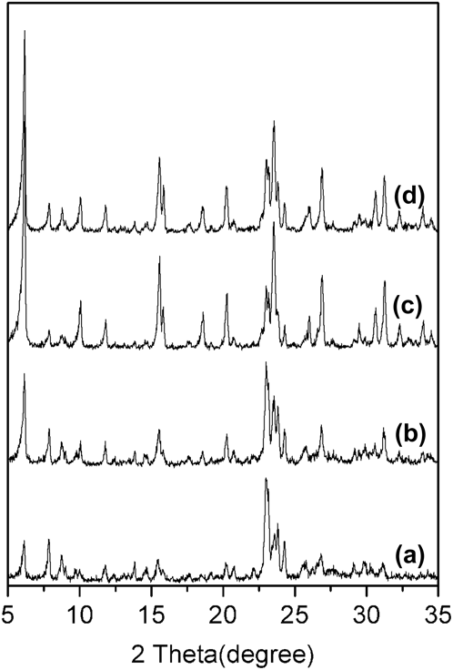
Depolymerization of the presynthesized zeolite crystals in basic medium is a key aspect to attain the aimed zeolite–zeolite composites.Reference Zheng, Zeng, Yi, Wang, Ma, Qin, Zhang, Sun and Li10,Reference Zheng, Zeng, Zhang, Wang, Ma, Zhang, Sun and Li11 The metastable ZSM-5 zeolite framework in alkaline solutions can provide partial nutrients for the growth of Y zeolite during the second-step synthesis. Figure 1 shows the XRD patterns of the as-synthesized MFI–FAU zeolite–zeolite composite with the different second-step crystallization time. The peaks at 6.16°, 10.08°, and 20.24° are the characteristic diffraction peaks of FAU zeolite phase,Reference Yee and Yaacob28 and the peaks at 7.90°, 8.75°, and 23.00° are the characteristic peaks of MFI zeolite phase.Reference Jin, Cui, Rui and Li29 The above-mentioned results indicate the co-existence of Y and ZSM-5 zeolite phases in the as-synthesized samples. It can be seen from Fig. 1 that prolonging hydrothermal treatment time resulted in the decreased characteristic diffraction peaks of ZSM-5 zeolite while the enhanced characteristic peaks of Y zeolite, suggesting that the preparation procedure of MFI–FAU is a process of MFI structure transferred into FAU structure.
XRD patterns of zeolite–zeolite composites MFI–FAU(t) prepared with the different crystallization time: (a) MFI–FAU(12); (b) MFI–FAU(15); (c) MFI–FAU(18); (d) MFI–FAU(21).

When the crystallization time was shorter than 12 h, the mass fraction of Y zeolite phase in the as-synthesized zeolite–zeolite composite is negligible because the time is not enough to provide solubilization of silicate to promote crystallization of Y zeolite due to the silicon species can only be obtained from the depolymerization of ZSM-5 zeolite crystals. The result also indicates that the growth of Y zeolite crystals may be lagged after the depolymerization of ZSM-5 zeolite. When the crystallization time was 12–21 h, zeolite–zeolite composites with different ratios of Y to ZSM-5 were obtained. Perhaps the degradation of ZSM-5 crystals by the synthesis solution is such as to provide enough solubilized silicon speciesReference Zheng, Zeng, Yi, Wang, Ma, Qin, Zhang, Sun and Li10,Reference Zheng, Zeng, Zhang, Wang, Ma, Zhang, Sun and Li11 to accelerate the growth of Y zeolite. However, when the crystallization time was further prolonged, such as over 30 h, a product abundant in Y zeolite commingled with P-type zeolite was obtained, and the characteristic peaks of ZSM-5 zeolite phase may completely disappear (not shown here). Extensive dissolution of ZSM-5 zeolite crystals makes the synthesis system to deviate from the crystallization field of the given zeolite Y.Reference Zheng, Zeng, Yi, Wang, Ma, Qin, Zhang, Sun and Li10,Reference Zheng, Zeng, Zhang, Wang, Ma, Zhang, Sun and Li11 As a consequence, zeolite–zeolite composites MFI–FAU are difficult to be obtained.
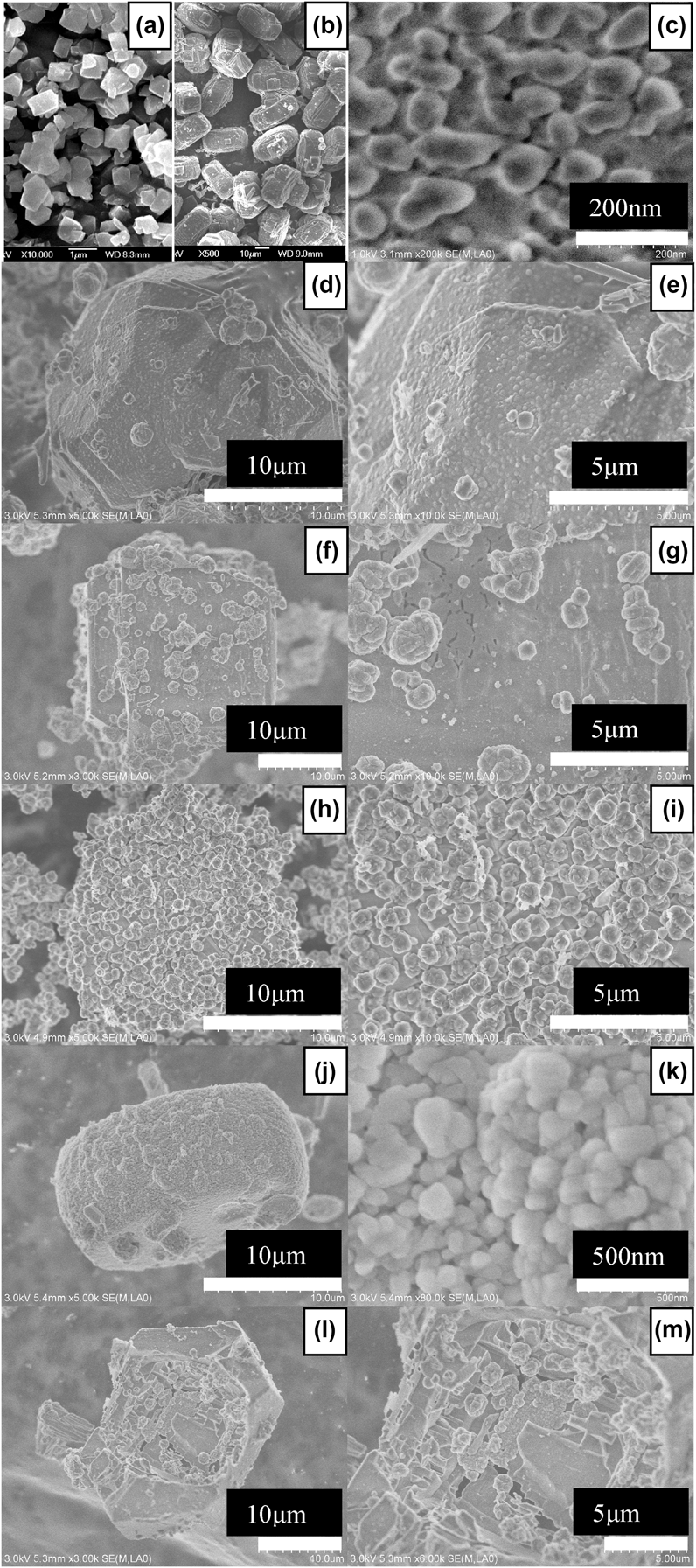
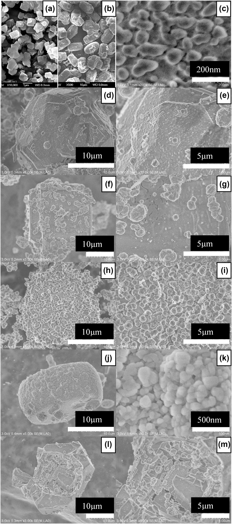
Crystal morphology of the zeolite–zeolite composite MFI–FAU(t) differs from those of Y and ZSM-5 zeolite crystals. As shown in Fig. 2, ZSM-5 and Y zeolite crystals show the block-like crystal particlesReference Teng, Wang, Chen, Liu and Wang14 and octahedralReference Zheng, Zeng, Yi, Wang, Ma, Qin, Zhang, Sun and Li10,Reference Zheng, Zeng, Zhang, Wang, Ma, Zhang, Sun and Li11,Reference Ren, Bai, Sun, Zhang and Fan13,Reference Jia, Sun, Ye, Zou, Gu, Huang, Niu and Zhao17 morphology, respectively. Either ZSM-5 or Y zeolite crystal displays a smooth external surface, and their sizes are about 10 μm × 10 μm × 30 μm and 1 μm, respectively. The seeds of Y zeolite in the dry powder display highly scattered nanosized particles with the size range from 10–70 nm [Fig. 2(c)]. It can be seen from Figs. 2(d)–2(k) that the composite MFI–FAU(t) samples have rougher surface because of the inlaid Y zeolite crystals on the external surface of ZSM-5 zeolite crystals. MFI–FAU(12) displays a rather coarse surface as shown in Figs. 2(d) and 2(e), the inlaid particles on MFI–FAU(12) still seem like the seeds of Y zeolite as shown in Fig. 2(c). Moreover, some faujasite crystals with a size of about 300–500 nm are clearly visible as shown in Fig. 2(e). It can be seen from Figs. 2(f)–2(i) that the external surfaces of MFI–FAU(15) and MFI–FAU(18) are decorated by polycrystalline aggregations, which are composed of about 1–2 μm flower-like crystals, and the flower-like crystals further consist of 100–300 nm faujasite crystals. Figure 2 also suggests that a longer hydrothermal treatment time leads to a thicker Y zeolites shells layer. Figures 2(j) and 2(k) exhibit that the ZSM-5 zeolite crystal in MFI–FAU(21) has been entirely covered by a polycrystalline shell composed of nanosized faujasite crystals with a size about 150–200 nm. The nanosized faujasite crystals in the zeolite–zeolite composite can be caused by the steric hindrance provoked by the concurrently growing crystals in the polycrystalline zeolite shells layer.Reference Zheng, Zeng, Zhang, Wang, Ma, Zhang, Sun and Li11,Reference Bouizi, Rouleau and Valtchev25,Reference Bouizi, Diaz, Rouleau and Valtchev26
SEM images: (a) pure Y zeolite; (b) pure ZSM-5 zeolite; (c) the as-synthesized seeds of Y zeolite; (d) and (e) MFI–FAU(12); (f) and (g) MFI–FAU(15); (h) and (i) MFI–FAU(18); (j) and (k) MFI–FAU(21); (l) and (m) MFI–FAU(18), which was crashed by 15 MPa pressure before tested by SEM.
Chemical composition of a given zeolite is an important characteristic, which defines its properties.Reference Zheng, Zeng, Zhang, Wang, Ma, Zhang, Sun and Li11 EDS analysis of zeolite–zeolite composites MFI–FAU(t) indicates that the SiO2/Al2O3 ratios of the flower-like crystals and the block-like crystal particles are 4.8–6.6 and 30–33, respectively, close to the 3.2 of Y zeolite and the 40 of ZSM-5 zeolites used in the experiments, respectively. The results reveal that the as-synthesized zeolite–zeolite composites are composed of ZSM-5 cores and Y zeolites shells. The EDS analysis also exhibits that the ZSM-5 zeolite phase in the composite has a decreased Si/Al ratio with the increased hydrothermal treatment time during the second-step synthesis. As shown in Fig. 3, the ratios of SiO2/Al2O3 of the ZSM-5 phase in the zeolite–zeolite composites MFI–FAU(12), MFI–FAU(15), MFI-FAU(18), and MFI–FAU(21) are 32, 33, 33, and 30, respectively, all lower than the 40 of the starting materials ZSM-5 zeolite. Moreover, the EDS analysis also suggests that the Y zeolite crystal in the zeolite–zeolite composites displays a relatively higher Si/Al ratio of about 4.8–6.6. The ratios of SiO2/Al2O3 of Y zeolites phase in MFI–FAU(12), MFI–FAU(15), MFI–FAU(18), and MFI–FAU(21) are 6.4, 6.2, 4.8, and 6.6, respectively. The aforementioned result strongly suggests that the silicon species have been transferred from the ZSM-5 zeolite cores to the Y zeolite shells.Reference Zheng, Zeng, Zhang, Wang, Ma, Zhang, Sun and Li11 The transforming process of silicon species from the ZSM-5 zeolite crystals to the Y zeolites crystals guarantees the formation of the target zeolite–zeolite composite samples. The extraction and transmission of silicon species during the second-step synthesis play an important role for the formation of MFI–FAU zeolite–zeolite composite.Reference Zheng, Zeng, Yi, Wang, Ma, Qin, Zhang, Sun and Li10 It is short of silicon species for the growth of Y zeolite crystals during the second-step hydrothermal crystallization, the silicon species needed for the growth of Y zeolite can only be obtained from the depolymerization of ZSM-5 zeolite.
EDS analysis of the as-synthesized zeolite–zeolite composites: (a) MFI–FAU(12); (b) MFI–FAU(15); (c) MFI–FAU(18); (d) MFI–FAU(21). The as-synthesized samples were crashed by 15 MPa pressure so as to discover its nature structure before the EDS analysis.

As shown in Figs. 2(l) and 2(m), a reverse growthReference Greer, Wheatley, Ashbrook, Morris and Zhou30,Reference Zeng, Bai, Zheng, Chen and Li31 of Y in ZSM-5 cores is also found in MFI–FAU(18) sample, which was crashed by 15 MPa pressure before tested by SEM, suggesting that the Y zeolite phase in MFI–FAU is also partially pregnant in ZSM-5 crystals. It is known that Al gradient affects and controls the Si extraction throughout the zeolite particles.Reference Groen, Zhu, Brouwer, Huynink, Kapteijn, Moulijn and Pérez-Ramírez32,Reference Groen, Bach, Ziese, van Donk, de Jong, Moulijn and Pérez-Ramírez33 In an alkaline solution, Si extraction from ZSM-5 zeolite crystals favorably occurs in the aluminum-poor bulk rather than the aluminum-rich external surface,Reference Groen, Zhu, Brouwer, Huynink, Kapteijn, Moulijn and Pérez-Ramírez32,Reference Groen, Bach, Ziese, van Donk, de Jong, Moulijn and Pérez-Ramírez33 due to a high framework, Al concentration prevents Si extraction. However, a low-Al concentration may lead to excessive extraction and formation of hollow zeolite crystals. During the second-step synthesis, a preferential dissolution of the aluminum-poor center results in the formation of hollow ZSM-5 crystals with a relatively preserved outer surface.Reference Zeng, Bai, Zheng, Chen and Li31–Reference Zheng, Zeng, Ma, Zhang, Sun and Li34 Under the direction of seeds of Y which are rather tinny as shown in Fig. 2(c), the extracted silicon species and the supplemented aluminum species, which diffuse from the synthesis solution through the ZSM-5 zeolite outer rim, promote the growth of Y zeolite crystals within the hollow ZSM-5 zeolite.Reference Zeng, Bai, Zheng, Chen and Li31 This allows us to propose a new formation mechanism of the zeolite–zeolite composite MFI–FAU and a new phase transformation mechanism from MFI structure to FAU structure. The formation mechanism of the zeolite–zeolite composite MFI–FAU(t) is different from that of overgrowthReference Okamoto and Osafune21,Reference Bouizi, Rouleau and Valtchev25,Reference Bouizi, Diaz, Rouleau and Valtchev26 or intergrowth,Reference Ohsuna, Terasaki, Nakagawa, Zones and Hiraga35 and is suggested in Scheme 1. Y zeolite nanoseeds are first adsorbed on the external surface of ZSM-5 zeolite crystal due to its higher surface area,Reference Zheng, Zeng, Ma, Zhang, Sun and Li34,Reference Dutta and Bronic36 which is a very important step for the formation of the zeolite–zeolite composites [Scheme 1. (a) → (b)]. Meanwhile, Si species are extracted from the framework of ZSM-5 zeolite by alkaline etching action of the synthesis solutionReference Groen, Moulijna and Pérez-Ramírez1,Reference Pérez-Ramírez, Christensen, Egeblad, Christensend and Groen2,Reference Yang, Tian, Chen, Li, Liu, Deng, Van Tendeloo and Su6,Reference Milina, Mitchell, Crivelli, Cooke and Pérez-Ramírez24 [Scheme 1. (b) → (c)]. Secondly, the nanoseeds gradually grow up because of the interaction between aluminum species from the synthesis solution and silicon species extracted from ZSM-5 zeolite crystals,Reference Zheng, Zeng, Zhang, Wang, Ma, Zhang, Sun and Li11 resulting in the formation of polycrystalline Y zeolite around ZSM-5 zeolite crystals, and ZSM-5 zeolite crystals are therefore embedded into the polycrystalline Y zeolite layersReference Okamoto and Osafune21 [Scheme 1. (c) → (d)]. Subsequently, the polycrystalline Y zeolite shells layer composed of small Y zeolite crystals becomes thicker and thicker along with the extracted process of silicon species from the ZSM-5 zeolite [Scheme 1. (d) → (e)]. With the extraction process of Si species, a hierarchical pore systemReference Groen, Moulijna and Pérez-Ramírez1,Reference Pérez-Ramírez, Christensen, Egeblad, Christensend and Groen2,Reference Yang, Tian, Chen, Li, Liu, Deng, Van Tendeloo and Su6,Reference Zheng, Zeng, Yi, Wang, Ma, Qin, Zhang, Sun and Li10,Reference Zheng, Zeng, Zhang, Wang, Ma, Zhang, Sun and Li11,Reference Milina, Mitchell, Crivelli, Cooke and Pérez-Ramírez24 is also introduced into the ZSM-5 zeolite crystal [Scheme 1. (b) → (e)]. Moreover, in an alkaline solution, Si-species extracted from ZSM-5 favorably occurs in the aluminum poor bulk rather than the aluminum-rich external surface,Reference Zeng, Bai, Zheng, Chen and Li31–Reference Groen, Bach, Ziese, van Donk, de Jong, Moulijn and Pérez-Ramírez33 which results in the formation of partial ZSM-5 hollow crystals. The supplemented aluminum species and highly scattered nanoseeds of Y zeolite diffuse from the synthesis solution through the ZSM-5 zeolite outer rim and promote the formation of Y zeolite crystals within the hollow ZSM-5 zeoliteReference Zeng, Bai, Zheng, Chen and Li31 [Scheme 1. (d) → (f)].
Schematic representation of the process for the formation of zeolite–zeolite composite MFI–FAU(t).
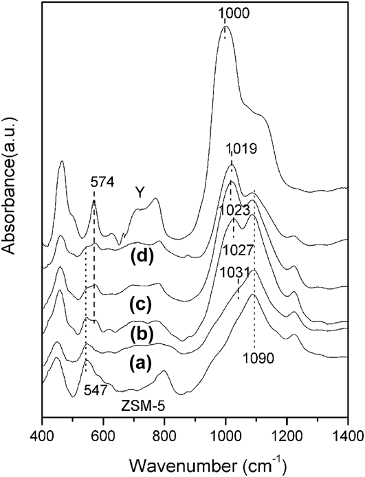
Figure 4 is the FT-IR spectra of the different samples. With a prolonged crystallization time, the band at 547 cm−1, which is attributed to the five member ring vibrations of ZSM-5 zeolite, is gradually weakened, while the band at 574 cm−1 attributed to the hexatomic ring vibrationsReference Kosanović, Havancsák, Subotić, Svetličić, Radić, Cziráki, Huhn, Buljan and Smrečki37 of Y zeolite crystals is gradually enhanced. The result implies that the framework of ZSM-5 zeolite is subjected to damaging along with formation of Y zeolite phase. That also suggests that the formation of the zeolite–zeolite composite is a gradual change process of MFI structure transformed into FAU structure.Reference Wang, Liu, Wang, Xie and Tang38 It can be seen from Fig. 1 that the mass fraction of Y zeolite phase in MFI–FAU(12) is negligible although the characteristic diffraction peaks of ZSM-5 zeolite have been dramatically decreased. It can be observed from Fig. 4 that the bands around 574 and 1031 cm−1, which respectively ascribed to the hexatomic ring vibrations and T-O-T antisymmetric stretching vibrations of Y zeolite crystals, are obviously observed in FT-IR spectra of MFI–FAU(12). The result suggests that the shorter crystallization time such as lower than 12 h, Y zeolite framework has practically been formed, and the negligible characteristic diffraction peaks of Y zeolite as shown in Fig. 1 can be therefore caused by the too small crystals to be detected by XRD. The vibration bands between 1000 and 1100 cm−1 are often used to identify the Si/Al ratio of the framework.Reference Morsli, Driole, Cacciaguerra, Arletti, Chiche, Hamidi, Bengueddach, Quignard and Di Renzo39 It can be seen from Fig. 4 that the band ascribed to the T-O-T antisymmetric stretching vibrations band of Y zeolite phase in the as-synthesized composite samples shifts from 1031 cm−1 of MFI–FAU(12), to 1027 cm−1 of MFI–FAU(15), 1023 cm−1 of MFI–FAU(18), and to the 1019 cm−1 of MFI–FAU(21), implying that the Si/Al ratio of the Y zeolite phase in the composite exhibits a decreased trend with the prolonged hydrothermal treatment time during the second-step synthesis. This is largely in agreement with the results observed by EDS as shown in Fig. 3.
FT-IR spectra of the different samples: (a) MFI–FAU(12); (b) MFI–FAU(15); (c) MFI–FAU(18); (d) MFI–FAU(21).
As shown in Fig. 5, the adsorption–desorption of nitrogen on Y or ZSM-5 zeolite is a type-I isotherm, indicating the presence of micropores only.Reference Zheng, Zeng, Yi, Wang, Ma, Qin, Zhang, Sun and Li10,Reference Zheng, Zeng, Zhang, Wang, Ma, Zhang, Sun and Li11 However, curves combining type-I and type-IV isotherms are observed for MFI–FAU(t) samples. Larger hysteresis loops occur after p/p 0 ≈ 0.45 in the adsorption–desorption isotherms of the zeolite–zeolite composite samples, indicating not only the presence of mesopores but also a broad pore size distribution.Reference Jin, Cui, Rui and Li29,Reference Chen, Lee, Zhang and Lu40 The mesopores created in the zeolite–zeolite composite can be ascribed to the silicon extractionReference Groen, Moulijna and Pérez-Ramírez1,Reference Pérez-Ramírez, Christensen, Egeblad, Christensend and Groen2,Reference Yang, Tian, Chen, Li, Liu, Deng, Van Tendeloo and Su6,Reference Zheng, Zeng, Yi, Wang, Ma, Qin, Zhang, Sun and Li10,Reference Milina, Mitchell, Crivelli, Cooke and Pérez-Ramírez24,Reference Jin, Cui, Rui and Li29 from ZSM-5 zeolite crystals by the alkaline synthesis solution and the polycrystalline accumulations of nanosized Y zeolite crystals in the shells. As shown in Fig. 5(inset), the pore size distribution of the MFI–FAU composites obtained from the adsorption branch of the isotherm illustrates the existence of a mesopore structure with pore sizes centering at about 10 nm. Moreover, significant increase in N2 adsorption is also observed from p/p 0 ≈ 0.8 for the as-synthesized samples. According to the SEM results mentioned above, zeolite–zeolite composite MFI–FAU(t) displays agglomerates of nanosized Y crystals. The sharp condensation in the range of p/p 0 ≈ 0.8 in N2 adsorption of MFI–FAU(18) and MFI–FAU(21) can therefore be mainly attributed to capillary condensationReference Bjøgen, Joensen, Holm, Olsbye, Lillerud and Svelle41 in open mesopores obtained by filling the interparticle spaces.Reference Simon-Masseron, Marques, Lopes, Ramô Ribeiro, Gener and Guisnet42 However, the BJH pore size distribution derived from the adsorption branch does not show a similar distribution in the corresponding pure Y or ZSM-5 as shown in Fig. 5 (inset).
N2 adsorption–desorption isotherms and the corresponding BJH pore size distribution curves (inset) of the as-synthesized zeolite–zeolite composites MFI–FAU(t) and the references pure Y and ZSM-5 zeolites.
Some N2 adsorption–desorption data are presented in Table I. MFI–FAU(18) has a BET surface area of 491 m2/g, lower than the 545 m2/g of the corresponding physical mixture with the similar Y/ZSM-5 ratio and similar chemical composition. Decreased Brunauer-Emmett-Teller (BET) surface area in the composites can be caused by the dissolution and partial amorphization of the starting ZSM-5 zeolite framework.Reference Zheng, Zeng, Yi, Wang, Ma, Qin, Zhang, Sun and Li10,Reference Zheng, Zeng, Zhang, Wang, Ma, Zhang, Sun and Li11 It can be inferred from Table I that a prolonged hydrothermal treatment time leads to an increased BET surface area in the composites. Obviously, the BET surface areas, microporous surface areas, and volume of the as-synthesized samples are decided by both of the dissolution of ZSM-5 and the growth of Y. The growth of Y zeolite crystals can offset the effect of the dissolution of ZSM-5 zeolite crystals on the microporous surface areas and volume as well as the BET surface areas in the composites. Table I also shows that the mesoporous areas and volumes in the composites largely depend on the crystallization time, the longer treatment time, the larger mesoporous areas or volumes.
Physical structural properties of samples.
a MFI + FAU is the corresponding physical mixture of sample MFI–FAU(18).
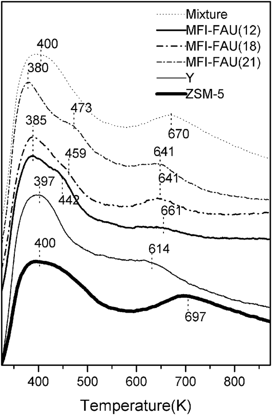
The zeolite–zeolite composite samples as well as the corresponding physical mixture, Y and ZSM-5 zeolites were investigated by NH3-TPD of ammonia experiments. As shown in Fig. 6, the TPD profile of pure Y zeolite displays two desorption peaks with maxima in the temperature regions at about 397 and 614 K; while ZSM-5 exhibits two desorption peaks at about 400 and 697 K. The TPD profile of zeolite–zeolite composite shows three desorption peaks with a distribution at 641–661, 442–473, and 380–385 K, which can be assigned to the desorption of NH3 from medium–strong and weak acid sites, respectively. It can be seen from Fig. 6 that the peak corresponding to the medium–strong acid sites in the curves of the TPD profiles shifts from 670 K of the corresponding physical mixture to the 641–661 K of the zeolite–zeolite composites, while the low-temperature desorption peak corresponding the weak acid sites shifts from 400 K of the physical mixture to the 380–385 K of the composite samples. The strength of the weak and the medium–strong acid sites in the composite samples is obviously weakened, which can be ascribed to the partial depolymerization of the framework of MFI zeolite phase in the zeolite–zeolite composites during the second-step synthesis. Desorption peak at about 442–473 K should be contributed to the formation of a new acid siteReference Zhang, Fan, Liu and Li20 resulted from the depolymerization of the ZSM-5 zeolite framework.Reference Zheng, Zeng, Yi, Wang, Ma, Qin, Zhang, Sun and Li10,Reference Zheng, Zeng, Zhang, Wang, Ma, Zhang, Sun and Li11 With an increased content of Y zeolite phase, the peak corresponding to ether the medium–strong acid or the weak acid shifts to the lower temperature. The peak corresponding to medium–strong acid sites shifts from 661 K of MFI–FAU(12) to 641 K of MFI–FAU(18) and MFI–FAU(21); while the peak related with weak acid sites shifts from 385 K of MFI–FAU(12) to the 380 K of MFI–FAU(21).
NH3-TPD curves of the as-synthesized zeolite–zeolite composites MFI–FAU(t), the pure Y, and ZSM-5 zeolite samples.

B. Catalytic tests
In the present study, catalytic cracking of isopropylbenzene was selected to investigate the catalytic performances of MFI–FAU(t) and compared with Y, ZSM-5, and the corresponding physical mixture MFI + FAU with the similar Si/Al and Y/ZSM-5 ratios to those of MFI–FAU(18). It can be seen from Fig. 7 that Y zeolite has a higher conversion of isopropylbenzene than ZSM-5 because of its higher medium–strong acid sites as shown in Fig. 6. The larger micropores channel in Y zeolite may attribute to a faster diffusion for the cracking products, which also contributes to enhancing the conversion of isopropylbenzene. Figure 7 also shows that the physical mixture MFI + FAU has a better catalytic performance than the single Y or ZSM-5 during the isopropylbenzene catalytic cracking, which can be ascribed to the synergistic effectReference Guo, Xiong, Huang and Li22,Reference Huang, Guo, Deng, Xue and Li23,Reference Dzikh, Lopes, Lemos and Ribeiro43,Reference Dzikh, Lopes, Lemos and Ribeiro44 of the different zeolite catalysts.
Catalytic cracking of isopropylbenzene over the zeolite–zeolite composite MFI–FAU(t), pure Y, pure ZSM-5, and the physical mixture MFI + FAU catalysts at 573 K.
It is well known that acid property of zeolite plays an important role in catalytic cracking performance. Obviously, MFI–FAU(t) zeolite–zeolite composites have different acid properties, catalytic activities, and stabilities. However, the catalytic activities and stabilities of the catalysts do not vary monotonously with the acid amounts and distributions. As shown in Fig. 7, it is difficult to observe the remarkable differences about the initial conversion of isopropylbenzene over the catalyst MFI–FAU(18) and the corresponding physical mixture MFI + FAU. However, as compared to MFI–FAU(18), the physical mixture MFI + FAU shows relatively lower stability with the prolonged reaction time. The conversion of isopropylbenzene over the physical mixture decreases from 98% at 0.1 h to about 50% at 4.5 h. While the conversion of isopropylbenzene over the zeolite–zeolite composite MFI–FAU(18) catalysts remains relatively stable. After 7 h, a 70% conversion of isopropylbenzene can still be obtained over the catalyst MFI–FAU(18). Severe diffusion limitationReference van Donk, Janssen, Bitter and de Jong4,Reference Su, Sanchez and Yang7,Reference Zheng, Zeng, Yi, Wang, Ma, Qin, Zhang, Sun and Li10,Reference Zheng, Zeng, Zhang, Wang, Ma, Zhang, Sun and Li11,Reference Groen, Zhu, Brouwer, Huynink, Kapteijn, Moulijn and Pérez-Ramírez32,Reference Groen, Bach, Ziese, van Donk, de Jong, Moulijn and Pérez-Ramírez33 in the physical mixture catalyst composed of purely microporous zeolites causes a quick deactivation due to carbon deposition; Moreover, MFI–FAU(21) with more mesopores gives the catalyst a higher catalytic activity and a higher stability than MFI–FAU(18) with relatively less mesopores, which confirms that the mesopores play an important role in isopropylbenzene catalytic cracking. Similar results were also observed by several groups.Reference Zhang, Qu, Wang, Zhang and Liu45–Reference Diao, Wang, Zhang and Liu47
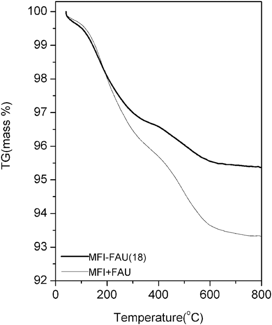
The amount of the carbonaceous deposits formed on MFI–FAU(t) and the corresponding physical catalysts MFI + FAU after approximately 7 h on stream were studied by TG characterizations. The TG curves as shown in Fig. 8 reveal for both catalysts, a substantial weight loss in the temperature range of 400–630 °C, that correspond to the burning-off of the coke deposits.Reference Martínez, Peris, Derewinski and Burkat-Dulak48 The weight loss in that range is 1.1% for MFI–FAU(18) and 1.7% for the corresponding physical mixture catalysts MFI + FAU reflecting a higher amount of carbonaceous deposits in the later. Coke formed much more rapidly in the purely microporous MFI + FAU reference catalyst than in the hierarchical zeolite–zeolite composite MFI–FAU(18) (12 mg/g in the composite catalyst and approximately 17 mg/g in the corresponding physical mixture catalyst) during the initial reaction period up to 7 h.
TG analyses of coked catalysts after being used for catalytic cracking of isopropylbenzene during approximately 7 h.
It is reasonable to assume that, therefore, the introduced hierarchical pore systemReference Groen, Moulijna and Pérez-Ramírez1,Reference Pérez-Ramírez, Christensen, Egeblad, Christensend and Groen2,Reference Yang, Tian, Chen, Li, Liu, Deng, Van Tendeloo and Su6,Reference Su, Sanchez and Yang7,Reference Zheng, Zeng, Yi, Wang, Ma, Qin, Zhang, Sun and Li10,Reference Zheng, Zeng, Zhang, Wang, Ma, Zhang, Sun and Li11,Reference Jin, Cui, Rui and Li29 may play a crucial role in the catalytic performances. The enhanced stabilities observed in the zeolite–zeolite composite catalysts can be ascribed to the introduced mesopore or macropore structure, which avails the faster diffusionReference Zheng, Zeng, Zhang, Wang, Ma, Zhang, Sun and Li11,Reference Groen, Zhu, Brouwer, Huynink, Kapteijn, Moulijn and Pérez-Ramírez32,Reference Groen, Bach, Ziese, van Donk, de Jong, Moulijn and Pérez-Ramírez33 of products from the active centers in its channel and depresses the carbon deposition as observed in TG experiment. The hierarchical pores system created in the zeolite–zeolite composites also gives the reactants easy access to the acid sites, especially the Brönsted-acid sites.Reference Diao, Wang, Zhang and Liu47,Reference Zheng, Zhang, Zhang, Ma and Li49 That also contributes to giving the catalyst a relatively high activity and stability.
The excellent catalytic performance of MFI–FAU during the catalytic cracking of isopropylbenzene can also be partially attributed to the special structure of the zeolites–zeolite composite. The transmission distance of the reactant between the two active components of Y and ZSM-5 is dramatically shortened as compared with the physical mixture of Y and ZSM-5 zeolite crystals. The special structure of ZSM-5 overgrown with Y (in most cases) guarantees a positive transmission way of reactant from the relatively larger micropore channels of Y zeolites (0.74 nm) to the relatively smaller micropore channels of ZSM-5 zeolite (0.54 nm) that attributes to affording a hierarchically catalyticReference Yang, Tian, Chen, Li, Liu, Deng, Van Tendeloo and Su6,Reference Na and Somorjai50–Reference Zhao, Qin, Zheng, Du, Sun, Ling, Zhang and Li54 cracking process for the relatively larger reactant molecular. Reactant can be first cracked over Y zeolite crystals and the precracked products can be recracked over ZSM-5 zeolite crystals with the relatively small pore channels. That contributes to enhancing the activity and stability of the zeolite–zeolite composite catalysts. However, the transmission distance and transmission way of the reactant in the purely microporous physical mixture MFI + FAU are random and uncertain. Composites MFI–FAU may have a potential application in the heavy oil cracking procedure because of the adjustable ratios of Y to ZSM-5 and the created hierarchical pores system, which may improve the properties of the cracking products. For example, the oil/olefin ratio in the products of heavy oil cracking can be tunable by using the zeolite–zeolite composites with the adjustable ratio of Y to ZSM-5 as a cracking catalyst.
IV. CONCLUSIONS
Zeolite–zeolite composites MFI–FAU composed of ZSM-5 and nanosized polycrystalline Y were successfully prepared. Besides overgrowing on the external surface, the postsynthesized Y zeolites crystals also displayed a partial reverse growth within the ZSM-5 crystals. The FAU/MFI ratio of the as-synthesized zeolite–zeolite composites can be adjusted by controlling the hydrothermal treatment time. A hierarchical pores system was introduced into the zeolite–zeolite composites because of the alkali-etched action on ZSM-5 zeolite crystals and polycrystalline accumulations of nanosized Y zeolites crystals. The created meso- and macropores structure gave the composite catalyst an excellent catalytic performance with the higher activities and higher stabilities as compared with the corresponding physical mixture composed of the purely microporous zeolites. The special composite structure guarantees a positive transmission way of reactant from the larger micropore channel of Y zeolites to the relatively smaller one of ZSM-5 zeolite. That attributes to affording a hierarchically catalytic cracking process for the relatively larger reactant.
ACKNOWLEDGMENTS
This work is supported by the Joint Funds of the National Natural Science Foundation of China–China Petroleum and Chemical Corporation (the State Key Program Grant No. U1463209); the National Natural Science Foundation of China (Grant Nos. 21371129; 21376157; 51272169).