Nomenclature
Abbreviations
- A
-
Energy (J)
-
 $\omega$
-
Angular velocity (rad/s)
- Iv
-
Mass moment of inertia
- mi
-
Mass (kg)
- m
-
Meter (m)
- J
-
Joule
- kg
-
Kilogram
- Gv
-
Weight (kg)
- Dv
-
Diameter (m)
- r
-
Radius (m)
- g
-
Gravitational acceleration
-
$\rho$
-
Density (kg/m3)
- MPa
-
Megapascal
- N
$\,\cdot\,$
m
-
Newton meter
- rpm
-
Revolutions per minute
- lb
-
Pound (0.45 kg)
- ft
-
Foot (0.30 m)
- BAK
-
Barrier Arresting Kit
- FAA
-
Federal Aviation Administration (United States)
- USAF
-
United States Air Force
- UDS
-
Aircraft Arresting System


1.0 Introduction
Ensuring the safe deceleration of fighter aircraft within runway limits during aborted take-offs or emergency landings is a critical operational requirement. Conventional aircraft braking systems may be insufficient under certain failure conditions or technical malfunctions. In such scenarios, aircraft arresting systems (AAS) are employed to safely stop the aircraft. These systems, also referred to as barrier systems, vary in configuration depending on the installation site and arresting method. Globally, approximately 2,000 AAS are operational across facilities in 64 countries [Reference Güngördü1].
Three primary types of AAS have been developed and deployed worldwide: barrier nets, arresting cables and engineered materials arresting systems (EMAS) (Fig. 1) [Reference Güngördü1–Reference Fedder and Hasberry3]. All three systems incorporate energy-absorbing units that dissipate the kinetic energy of the aircraft during deceleration. The force applied by these units is a critical parameter for evaluating the suitability of the barrier system, and the system must stop the aircraft within a predefined distance.
The net-type barrier system (Fig. 1(a)) captures the aircraft fuselage using a net, which is elevated to the required position by a lifting mechanism. The system also includes control and braking units depending on the barrier configuration. These barriers are typically installed at runway thresholds and are designed to stop aircraft within the overrun area [Reference Fedder and Hasberry3]. Energy absorption can be achieved using friction disc brakes, hydraulic systems leveraging fluid compressibility or other mechanisms that convert kinetic energy into controlled resistance. Globally, hydraulic systems are preferred for emergency applications due to their higher energy absorption capacity [Reference Licu and Rayo4, Reference Jones5].
In cable-type systems (Fig. 1(b)), the aircraft deploys a tailhook to engage a steel cable spanning the runway width. The cable is then tensioned and connected to hydraulic braking units at the runway edges. During deceleration, the tailhook pulls the cable, generating frictional resistance through the system to slow the aircraft [Reference Bachtel2].
EMAS (Fig. 1(c)) decelerate aircraft over soft, crushable surfaces at runway ends, allowing safe stops within distances shorter than 305 m (1,000 ft) [Reference Woods6]. These surfaces are specifically engineered with controlled strength and thickness to manage aircraft kinetic energy.
While net and cable systems are predominantly used for military fighter aircraft, EMAS is increasingly deployed at civilian airports lacking sufficient overrun areas. Despite differences in the interface between the aircraft and the arresting system, net and cable systems often employ similar braking mechanisms.
UDS systems: (a) Net barrier system, [Reference Fedder and Hasberry3] (b) arresting cable system, [Reference Fedder and Hasberry3] and (c) engineered materials arresting system [Reference Woods6].

When designing new barriers, North Atlantic Treaty Organization (NATO) standards define the testing requirements. MIL-STD-3036 specifies the tests for newly designed barrier systems, which are currently conducted exclusively at the Naval Air Warfare Center Aircraft Division Lakehurst in the United States. The standard prescribes a matrix of tests involving dead loads at varying speeds and weights, known as ‘dead-load tests’. High costs associated with these tests present significant challenges for barrier development and production continuity.
With the growing development of manned and unmanned military aircraft, all fighter-class aircraft require barrier systems. This study presents a fully domestic, novel AAS test unit capable of performing MIL-STD-3036 equivalent tests. The system calculates the kinetic energy corresponding to specified speed and weight combinations and transfers this energy via flywheels to the barrier, allowing dead-load tests to be conducted without conventional heavy infrastructure [7].
Flywheel systems have been extensively used in energy storage and various industrial applications due to their efficient kinetic energy storage capabilities. However, their application as a controlled energy input mechanism for AAS testing has not been sufficiently explored. Existing AAS validation approaches primarily rely on full-scale dead-load testing, which requires substantial infrastructure, high operational costs and limited testing flexibility. In this context, the proposed flywheel-based system introduces a novel approach that enables controlled, repeatable and cost-effective testing within a laboratory environment. This study addresses this gap by presenting the conceptual design and analytical modelling of the proposed system [Reference Bolund, Bernhoff and Leijon8].
In the current state of practice, AAS testing is predominantly performed using dead-load test methods conducted on long runways under full-scale operational conditions. Such test setups require extensive infrastructure, high operational cost and limited flexibility in experimental configuration. Existing literature primarily focuses on the evaluation and characterisation of arresting system performance within these established testing infrastructures.
In contrast, this study proposes a novel experimental test unit that enables laboratory-scale evaluation of AAS behaviour. The developed system utilises the energy storage capability of flywheels, which are adapted according to the required test conditions to replicate impact energy under controlled settings. This approach allows for a more flexible, repeatable and cost-effective testing environment compared to conventional full-scale runway-based tests.
The proposed test platform is intended to provide an alternative solution with significantly reduced infrastructure requirements, thereby supporting the qualification and preliminary validation of new AAS designs at an early development stage.
2.0 Methodology
2.1 Development of the test system for aircraft arresting systems
A novel AAS test unit was developed to provide an alternative to conventional testing methods and to comply with the MIL-STD-3036 standard. The system is designed to evaluate both serviced AAS units before deployment and newly designed AAS units to ensure certification and operational reliability. Figure 2 illustrates the general configuration of the developed test system, including the test unit and its main components.
(a) Developed AAS test unit, (b) aircraft arresting system and (c) flywheel and drum mechanism of the test system.

The test system operates by loading kinetic energy into one or more flywheels via electric servomotors, in accordance with the energy levels specified in MIL-STD-3036. The energy stored in the flywheels is subsequently transferred to the barrier through a nylon strap, which activates the arresting mechanism. The hydraulic system of the barrier engages during the test, replicating the aircraft entry conditions and producing braking forces to decelerate the simulated aircraft. Complete halting of the flywheel at the end of the strap is required for a successful test. If the flywheel does not stop, the test is considered unsuccessful, and the residual kinetic energy is calculated to quantify the energy not absorbed by the barrier.
In order to facilitate analytical modelling, several simplifying assumptions have been adopted in this study. Mechanical losses such as bearing friction, belt slip and aerodynamic drag are neglected in the initial analysis. Based on typical rotating machinery performance, these losses are generally estimated to remain within approximately 3–5% of the total system energy and are, therefore, considered to have a limited effect on the overall energy balance at this stage of design.
The assumption of approximately constant arresting force is consistent with the functional characteristics of AAS, which are designed to produce near-uniform deceleration during aircraft engagement.
2.2 Flywheel design and material selection
Critical design parameters for the flywheels included material selection, allowable stress limits, required flywheel diameter, rotational speed and mass necessary to store the specified kinetic energy. To store the required energy, two identical flywheels were designed, maximising diameter while minimising rotational speed for safety. The energy required for the flywheel system to store has been optimised based on materials available on the market for casting and manufacturable dimensions. Two flywheels have been used to ensure the system operates in a balanced manner. A dual-flywheel configuration was implemented to maintain rotational stability and minimise mechanical disorders during high-speed energy transfer. To eliminate the need for complex external synchronisation controls, both flywheels are mounted on a single rigid shaft, ensuring that they operate as a unified inertial mass.
In determining the flywheel rotation speed, industrial coupling limits and cost-effective flywheel materials were evaluated. The rotation speed was optimised based on the radial and tangential stresses generated on the material depending on the rotation speed. As environmental safety measures, it was planned that the bases on which the main shaft is supported would be at a certain depth from the ground and that the flywheels would be in an enclosed area where no personnel would be present during operation.
The flywheel material, GS20Mn5, was selected due to its high yield strength (460 MPa) and its compatibility with the casting and manufacturing infrastructure available in Türkiye. The design was optimised for a 3-m diameter scale, which aligns with local foundry capacities. To ensure operational safety, the maximum rotational speed was set at 600 rpm. At this speed, radial and tangential stresses remain well within the material’s elastic limits, providing a robust safety factor for repeated testing cycles [Reference Genta9, Reference Li and Palazzolo10].
Residual stresses resulting from casting and manufacturing processes have not been explicitly modelled, as the current study is limited to conceptual design and preliminary analytical evaluation. Accordingly, material properties are assumed based on standard values provided by material specifications.
Reference values for the flywheel design were determined as follows:
-
• Material: GS20Mn5
-
• Manufacturing method: Casting
-
• Diameter: 3 m
-
• Rotational speed: 600 rpm
-
• Required flywheel thickness: 0.24 m
The resulting angular velocity, moment of inertia, and stored energy were calculated as:
Angular velocity of the flywheel:
 \begin{align}\omega = \frac{{2.\pi .n}}{{60}} = 62,83\,\textrm{rad/s}\end{align}
Moment of inertia of the flywheel:
 \begin{align}I = \frac{{m.{r^2}}}{2} = 30.037,\!5\,\textrm{kg.m}^{2}\end{align}
Amount of energy stored in the flywheel:
 \begin{align}A = \frac{{I.{\omega ^2}}}{2} = 59.268.740\,\textrm{J}\end{align}
Maximum tangential and radial stresses were computed to ensure structural integrity:
 \begin{align}{\sigma _{tmax}} = \frac{{\rho {\omega ^2}}}{4}\left( {\left( {1 - \upsilon } \right)\!r_1^2 + \left( {3 + \upsilon } \right)\!r_2^2} \right) = 359,\!174\,\textrm{Mpa} \end{align}
has been calculated, and in addition, the maximum radial stress:
 \begin{align}{\sigma _{rmax}} = \rho {\omega ^2}\left( {\frac{{\left( {3 + \upsilon } \right)}}{8}} \right){\left( {{r_2} + {r_1}} \right)^2} = 179,\!59\,\textrm{Mpa}\end{align}
Casting was selected as the manufacturing method to produce the flywheel with the specified dimensions. In order for the flywheel material to withstand the calculated maximum stress value of 359.174 MPa, GS20Mn5 steel, with a yield strength of 460 MPa, was chosen. The kinetic energy values required to be stored, based on the weight and speed variations provided in the table of the MIL-STD-3036 standard, are presented in the tables.
Test matrix for a 366 m run-out distance in accordance with MIL-STD-3036

Table 1 Long description
A table with 10 rows and 10 columns. The columns are labeled No., Dead-load weight (kgf), and Dead-load arresting speed (m/s). The table presents data on dead-load weight and corresponding dead-load arresting speeds. Row 1: No. 1, Dead-load weight 8.617 kgf, Dead-load arresting speed 41, 51, 62, 72, 82, 87, 93, 98 m/s. Row 2: No. 2, Dead-load weight 11.338 kgf, Dead-load arresting speed 41, 51, 62, 62, 62, 72, 72, 72 m/s. Row 3: No. 3, Dead-load weight 13.152 kgf, Dead-load arresting speed 41, 51, 62, 72, 77, 82, 93, 98 m/s. Row 4: No. 4, Dead-load weight 15.873 kgf, Dead-load arresting speed 41, 51, 62, 62, 62, 72, 72, 72 m/s. Row 5: No. 5, Dead-load weight 17.687 kgf, Dead-load arresting speed 41, 51, 62, 72, 82, 87, 93, 98 m/s. Row 6: No. 6, Dead-load weight 21.315 kgf, Dead-load arresting speed 41, 51, 62, 72, 77, 82, 87, 93 m/s. Row 7: No. 7, Dead-load weight 26.303 kgf, Dead-load arresting speed 41, 51, 62, 67, 72, 77, 82, 87 m/s. Row 8: No. 8, Dead-load weight 31.292 kgf, Dead-load arresting speed 41, 51, 62, 67, 72, 77, 82, 87 m/s. Row 9: No. 9, Dead-load weight 34.013 kgf, Dead-load arresting speed 41, 51, 51, 62, 62, 72, 72, 72 m/s. Row 10: No. 10, Dead-load weight 38.548 kgf, Dead-load arresting speed 41, 46, 51, 57, 62, 67, 72, 77 m/s.
This corresponds to a factor of safety of approximately 1.28, which is acceptable for preliminary design purposes, while indicating potential for further refinement in future studies.
The weight and speed table specified in the relevant standard for the tests to be conducted is given in Table 1. This table presents the different dead-load weights to be used in the tests along with the corresponding entry speeds of these dead loads into the AAS [Reference Genta9].
This table presents the dead-load weights required for the tests and the corresponding entry speeds at which these loads must enter the AAS. For ten different dead-load weights, eight tests are planned for each case, resulting in a total of 80 tests. In accordance with the references specified in the standard, the required flywheel rotational speeds and the corresponding kinetic energy magnitudes obtained at these speeds – necessary for testing the AAS using defined dead-load speeds instead of aircraft of different weights – are illustrated graphically in Fig. 3.
Required flywheel rotational speed and absorbed energy for aircraft with dead-load weights of, respectively: (a) 8,617 kgf, (b) 11,338 kgf, (c) 13,152 kgf, (d) 15,873 kgf, (e) 17,687 kgf, (f) 21,315 kgf, (g) 26,303 kgf, (h) 31,192 kgf, (i) 34,013 kgf and (j) 38,548 kgf.

The braking systems integrated into AAS exhibit different responses depending on the aircraft’s speed. Therefore, the entry speed of the aircraft into the arresting system directly affects the arresting force acting on the aircraft during the braking process. During the dynamic phase, heavier aircraft decelerate less than lighter ones. As a result, a greater arresting force is applied to the aircraft hook at the same entry speeds. When the operating conditions exceed the capacity of the AAS, the arresting force generated by the system decreases, leading to unsuccessful arrestment. During the aircraft stopping process, both the speed and the weight of the aircraft directly influence the AAS in terms of motion dynamics. In order to determine this force, experimental aircraft arrestment tests were conducted during the early development stages of AAS using aircraft with different weights and speeds. Based on the results obtained from these experiments, empirical relationships were derived to estimate the forces acting on AAS [Reference Altan11].
Based on 110 experimental trials conducted with several dead-load weights and speed configurations, the stopping forces acting on AAS during engagement were measured as a function of both mass and impact velocity. The resulting dataset was processed using a curve-fitting approach to establish an empirical relationship between the governing parameters, from which Equation (6) was derived. The force acting on the aircraft hook (arresting system) is given by Sati et al. [Reference Sati, Kanaskar, Kajale and Mukherjee12]:
 \begin{align}F = 43.000.{\rm{tan}}\left( {\frac{V}{{150}}} \right)(1 + {\rm{tan}}\left( {\frac{{w - 50.000}}{{450.452}}} \right)\end{align}
This relationship is used to determine the arresting force. In this formula, F (pound) represents the force applied to the hook, v (knot) denotes the aircraft entry speed into the AAS and w (pound) indicates the aircraft weight. Within this scope, the forces acting on the hook (arresting system) of the AAS were calculated based on the dead-load speeds, and dead-load speed–hook force graphs were obtained for each weight value (Fig. 4).
Velocity–force characteristics for aircraft with dead-load weights of, respectively: (a) 8,617 kgf, (b) 11,338 kgf, (c) 13,152 kgf, (d) 15,873 kgf, (e) 17,687 kgf, (f) 21,315 kgf, (g) 26,303 kgf, (h) 31,192 kgf, (i) 34,013 kgf and (j) 38,548 kgf.

According to the values given in Table 2, which presents the tests to be conducted for the evaluation of AAS, calculations performed using Equation (6) revealed that the maximum force acting on the hook occurs at a dead load of 17,687 kgf and an entry speed of 98 m/s. This force value was calculated as 244,342 N according to Equation (6). By calculating the force applied by the AAS to the aircraft hook, it becomes possible to determine the aircraft stopping time and deceleration. Based on the operating principle of the AAS test unit, energy is stored by rotating a flywheel, and this energy is subsequently dissipated by the AAS. The nylon tape wound around the AAS is reeled in by the test system, and during this process, the force applied to the shaft of the test unit generates a braking torque.
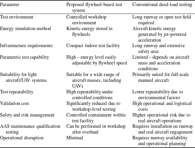
Comparison between the flywheel-based system and conventional dead-load testing

Table 2 Long description
A table comparing flywheel-based test system and conventional dead-load testing across various parameters. The table has 10 rows and 3 columns. Column headers are Parameter, Proposed flywheel-based test system, and Conventional dead-load testing. Row 1: Parameter, Proposed flywheel-based test system, Conventional dead-load testing. Row 2: Test environment, Controlled workshop environment, Long runway or open test field required. Row 3: Energy simulation method, Kinetic energy stored in flywheels, Aircraft kinetic energy generated by jet-powered acceleration. Row 4: Infrastructure requirements, Compact indoor test facility, Long runway and extensive safety area. Row 5: Parametric test capability, High energy level easily adjustable by flywheel speed, Limited depends on aircraft mass and acceleration conditions. Row 6: Suitability for light aircraft/UAV systems, Suitable for a wide range of aircraft masses, including UAVs, Primarily suited for full-scale manned aircraft. Row 7: Test repeatability, High repeatability under controlled conditions, Lower repeatability due to environmental factors. Row 8: Validation cost, Significantly reduced due to workshop-level testing, High operational and logistical costs. Row 9: Safety and risk management, Controlled containment within test facility, Higher operational risk due to real aircraft operations. Row 10: AAS maintenance qualification testing, Can be performed in workshop after overhaul, Requires installation on runway and real aircraft engagement. Row 11: Operational disruption, Minimal, Requires runway availability and operational planning.
The torque value is given as:
 \begin{align*} M = F.d{\rm{ }}\left( {N.m} \right) \end{align*}
[Reference Prabha and Raghavendra13]
The torque is determined by this formula. In this expression, F denotes the force in Newtons, d represents the perpendicular distance from the line of action of the force to the axis of rotation in meters and M indicates the torque in N·m. Based on the weight and speed configurations provided in the test matrix given in Table 1, the force values obtained were substituted into the torque equation, and the graphs illustrating the effect of dead-load weight and force on torque, as shown in the figures (Fig. 5), were obtained. In these graphs, the horizontal axis represents the force applied by the aircraft AAS to the test unit, while the vertical axis represents the corresponding torque value. A linear relationship between torque and force is clearly observed. Similarly, when the same calculations are performed for the remaining rows of the test matrix, the graphs in the figure are obtained.
As a result of the calculations, it was determined that, according to the data in the test matrix, the maximum torque acting on the test unit occurs at a dead load of 17,687 kgf and an entry speed of 98 m/s. This torque value was calculated as 249,688 N·m using the torque equation. AAS apply an approximately constant force to the aircraft hook during the arrestment process. This force causes a negative acceleration that brings the aircraft to a stop. In the test unit, this force generates a torque, and the torque acting on the rotating flywheel system tends to decelerate and stop the system. Accordingly, the applied torque produces a negative angular acceleration on the rotating system. The ratio of the net torque acting on the system to the moment of inertia is equal to the angular acceleration [Reference Li and Palazzolo10].
 \begin{align}\Sigma M = I\alpha \end{align}
When the angular acceleration is isolated from Equation (7), which expresses torque in terms of angular acceleration and moment of inertia, the following expression is obtained:
 \begin{align}\alpha = \frac{{\Sigma M}}{I}\end{align}
Using the torque values obtained from the previous calculations, the angular acceleration values were computed, and the results shown in Fig. 6 were obtained.
Force–moment characteristics for aircraft with dead-load weights of, respectively: (a) 8,617 kgf, (b) 11,338 kgf, (c) 13,152 kgf, (d) 15,873 kgf, (e) 17,687 kgf, (f) 21,315 kgf, (g) 26,303 kgf, (h) 31,192 kgf, (i) 34,013 kgf and (j) 38,548 kgf.

Moment–angular acceleration characteristics for aircraft with dead-load weights of, respectively: (a) 8,617 kgf, (b) 11,338 kgf, (c) 13,152 kgf, (d) 15,873 kgf, (e) 17,687 kgf, (f) 21,315 kgf, (g) 26,303 kgf, (h) 31,192 kgf, (i) 34,013 kgf and (j) 38,548 kgf.

As a result of these calculations, it was determined that the maximum angular acceleration acting on the test unit, according to the test matrix data, occurs at a dead load of 17,687 kgf and an entry speed of 98 m/s. This value was calculated as 8,31 rad/s2.
The study is in the design phase, and theoretical calculations and modeling have been performed. Since no experimental studies have been conducted, measurement-based error assessment has not been possible. In this analytical phase, secondary mechanical losses – including bearing friction, aerodynamic drag of the flywheels and potential strap slippage – are neglected to focus on primary energy transfer. These variables will be quantified during future high-fidelity experimental validation.
2.3 Safety and containment measures
Given the significant kinetic energy stored during operation, the system incorporates a subterranean containment strategy. The main shaft and flywheels are installed within a reinforced concrete pit located below the facility floor. This placement ensures that any potential component failure is safely contained within a restricted-access area. Real-time monitoring of rotational velocity is conducted using high-precision Hall effect sensors, which also serve as part of the automated emergency shut-off system.
2.4 Calculation of the stopping time of the aircraft arresting system test unit
AAS stops the rotation of the flywheels in the test unit by generating a negative angular acceleration. The magnitude of the angular acceleration acting on the system varies for different speeds and rotational rates, and as a result, the rotational motion of the test system comes to rest over different time intervals. The relationship between the negative angular acceleration acting on a rotating body and the angular velocity is expressed as follows:
 \begin{align}{\omega _2} = {\omega _1} - \alpha t\end{align}
In this expression, ω 1 represents the initial angular velocity, ω 2 the final angular velocity, α the angular acceleration and t the time. Since the complete stoppage of the flywheels in the test unit is targeted, the final angular velocity ω 2 is taken as zero. Rearranging the equation to solve for time yields:
 \begin{align}t = \frac{{{\omega _1}}}{\alpha }\end{align}
In this equation, t seconds, ω rad/s and α rad/s². Using this relationship, the stopping times of the test unit were calculated based on the rotational speeds defined in the test matrix and the angular acceleration values computed above, resulting in the values shown in Fig. 7. In this graph, the horizontal axis represents the angular acceleration, while the vertical axis represents the stopping time of the system. As the magnitude of the negative angular acceleration acting on the system increases, the stopping time decreases.
Angular acceleration–stopping time characteristics for aircraft with dead-load weights of, respectively: (a) 8,617 kgf, (b) 11,338 kgf, (c) 13,152 kgf, (d) 15,873 kgf, (e) 17,687 kgf, (f) 21,315 kgf, (g) 26,303 kgf, (h) 31,192 kgf, (i) 34,013 kgf and (j) 38,548 kgf.

As a result of the calculations, it was determined that the longest stopping time of the AAS test unit, according to the test matrix data, occurs at a dead load of 38,548 kgf and an entry speed of 41 m/s. This stopping time was calculated as 13.03 s.
2.5 Limitations and future roadmap
This study is currently limited to analytical validation and design optimisation. Future research will involve the construction of a scaled-down prototype to experimentally correlate the theoretical force-time histories. This roadmap includes the development of a measurement-based error assessment to account for the operational variabilities and mechanical losses.
3.0 Results
According to the operating conditions defined for the test system, the kinetic energy stored in a single flywheel at a rotational speed of 600 rpm was calculated as 66,335,000 J. This value represents the energy that can be stored by one flywheel used in the test system. Since two flywheels are employed in the system, a total energy of 132,670,000 J can be stored in the flywheels. It was observed that this value satisfies the maximum required energy of 118,537,479 J specified in the test matrix of the MIL-STD-3036 standard, which is taken as the reference for AAS tests.
In the study conducted to determine the forces acting on the aircraft hook in AAS test results, it was found that the AAS applies the maximum force to the test system at a configuration of 17,687 kgf dead load and 98 m/s entry speed. The magnitude of this force was calculated as 244,342 N.
For the same configuration of 17,687 kgf dead load and 98 m/s entry speed, this force was calculated to generate a torque of 249,688 N·m on the flywheels of the test system.
Based on the calculations performed using the values in the test matrix, the maximum angular acceleration was determined as 8.31 rad/s², occurring at the 17,687 kgf and 98 m/s configuration corresponding to the aforementioned torque value.
By calculating the test durations according to these angular acceleration values, it was determined that the longest test duration occurs at a configuration of 38,548 kgf dead load and 41 m/s entry speed, with a duration of 13.03 s.
As a result of this study, it becomes possible to establish a more economical test system that provides equivalent dynamic conditions for testing AAS, replacing conventional test setups that require high installation and operational costs – such as jet engines, runways, dead loads and dead-load carrier vehicles. Furthermore, performing tests on AAS after maintenance and prior to aircraft entry tests can significantly reduce risks associated with aircraft and pilot safety.
In addition, in the case of designing AAS operating on different principles using new technologies, or in studies addressing the requirements of alternative aerial platforms such as unmanned aerial vehicles, the test system developed in this thesis can be utilised for validation purposes. The proposed test system enables experimental investigations into the reliability, maintenance requirements, capacity and service life of newly designed arresting systems. Moreover, the expansion of testing capabilities – currently limited worldwide to a single facility in the United States – would become feasible, fostering a more competitive testing environment.
4.0 Conclusion
AAS are critical safety components for the operation of combat and training aircraft, and their development plays a key role in enhancing design flexibility for aircraft platforms. With the increasing development of fighter aircraft, training aircraft and unmanned aerial vehicles, the need for reliable and cost-effective ground support systems has become more pronounced.
One of the major challenges in the development and certification of AAS is the requirement for complex, high-cost testing infrastructures involving runways, jet engines, dead loads and carrier vehicles. In this study, a flywheel-based test unit capable of reproducing the required dynamic conditions defined in MIL-STD-3036 was designed and analytically validated.
The results demonstrate that the proposed test system is capable of safely meeting the maximum energy, force, torque, angular acceleration and stopping time requirements specified in the standard. By enabling laboratory-based testing under controlled conditions, the developed system offers a practical and economical alternative to conventional full-scale field tests.
In aircraft design, hook systems are adapted according to the force requirements specified in standards. The limits set by these standards affect aircraft design by adapting landing speed and weight. Since the needs of new aircraft designs will be within these limits, different platforms can be served by adapting the flywheel rotation speeds. Scaling will be done by adapting the flywheel rotation speeds according to the required energy amount.
Furthermore, the proposed test system provides a versatile platform for the validation of newly designed AAS operating under different principles, as well as for future aerial platforms such as unmanned aerial vehicles. The widespread adoption of such a test methodology has the potential to reduce certification costs, improve safety and increase global testing capacity beyond the currently limited facilities.
As in other rotating mechanical systems, several technical challenges are anticipated in the manufacturing and assembly of the proposed test rig. In particular, precise alignment of the shaft system is critical in configurations involving multiple shafts, as it directly affects both the efficiency of power transmission and the reliable operation of torque-transmitting couplings. Improper shaft alignment may lead to irregular system behaviour and undesirable dynamic responses.
Although it is expected that thermal loads will dissipate during the preparation period between successive tests of the AAS, the possibility of significant heat generation during experimental operation cannot be excluded. In such cases, the incorporation of an additional cooling system may be required to ensure safe and stable operation of the test setup.
Despite providing a useful baseline for the analysis of flywheel-based systems, the present study is subject to several limitations. The analysis is based on an idealised system representation in which effects such as structural damping variations, bearing friction nonlinearities and manufacturing tolerances are not explicitly modelled. In addition, dynamic phenomena including vibration-induced stresses, shaft misalignment and thermal expansion effects are not incorporated into the current formulation. These factors may result in deviations between the predicted and actual system behaviour, particularly under high-speed or long-duration operating conditions. Finally, the proposed model is validated within a limited experimental and operational range; therefore, its applicability outside this domain should be interpreted with caution. Future work will address these aspects to achieve a more comprehensive evaluation of flywheel system performance and durability.
Given that the flywheel is subjected to repeated cyclic loading during operation, fatigue performance – particularly high-cycle fatigue behaviour governed by S–N curve characteristics – constitutes a critical aspect of its structural integrity. This aspect was beyond the scope of the present study but will be addressed in future work to provide a comprehensive assessment of service life and durability.
Key contributions and benefits
-
• Cost-effective testing solution: Eliminates the need for high-cost infrastructure such as runways, jet engines and full-scale aircraft tests.
-
• Standard compliance: Successfully satisfies the maximum kinetic energy, force, torque, angular acceleration and stopping time requirements defined in MIL-STD-3036.
-
• Enhanced safety: Enables pre-flight validation of AAS after maintenance, reducing risks to aircraft and pilot safety.
-
• Scalability and flexibility: Allows testing of arresting systems for aircraft with different weights and entry speeds, including future platforms such as UAVs.
-
• Support for innovation: Provides a reliable experimental platform for validating newly developed AAS concepts operating with alternative technologies.
-
• Global testing capacity expansion: Offers the potential to decentralise AAS testing, currently limited to a single facility worldwide, and to promote a competitive testing environment.