1. Introduction
The Kelvin–Helmholtz (KH) instability has been ubiquitously observed in hydrodynamic fluids (Drazin Reference Drazin1970; Chandrasekhar Reference Chandrasekhar1981), plasmas (Horton, Tajima & Kamimura Reference Horton, Tajima and Kamimura1987), geophysical flows (van Haren & Gostiaux Reference van Haren and Gostiaux2010) and astrophysical situations (Foullon et al. Reference Foullon, Verwichte, Nakariakov, Nykyri and Farrugia2011). This instability occurs in the form of vortices at the interface between two flows due to either velocity shear or having sufficient relative velocity. The interactions between these KH vortices govern the transport processes like mixing and diffusion (Smyth & Moum Reference Smyth and Moum2012). The main objectives of this study are to explore the formation and evolution of KH vortices of a rotating dusty plasma and quantifying the mixing they generate using tracer particles simulation. The formation and evolution of these vortices depend on the shear and nature of the medium (here the viscoelasticity of the system). The KH instability for dust flows has also been investigated theoretically (d'Angelo & Song Reference d'Angelo and Song1990; Rawat & Rao Reference Rawat and Rao1993; Banerjee, Janaki & Chakrabarti Reference Banerjee, Janaki and Chakrabarti2012; Pandey, Vladimirov & Samarian Reference Pandey, Vladimirov and Samarian2012; Tiwari et al. Reference Tiwari, Dharodi, Das, Patel and Kaw2014b; Dolai, Prajapati & Chhajlani Reference Dolai, Prajapati and Chhajlani2016; Prajapati & Boro Reference Prajapati and Boro2021) and numerically (Ashwin & Ganesh Reference Ashwin and Ganesh2010; Tiwari et al. Reference Tiwari, Das, Kaw and Sen2012b,Reference Tiwari, Das, Angom, Patel and Kawa, Reference Tiwari, Dharodi, Das, Kaw and Sen2014a) as well as experimentally (Luo, D'Angelo & Merlino Reference Luo, D'Angelo and Merlino2001) for planar sheared flows. Rotating vortex flows have been studied considerably (Klindworth et al. Reference Klindworth, Melzer, Piel and Schweigert2000; Konopka et al. Reference Konopka, Samsonov, Ivlev, Goree, Steinberg and Morfill2000; Schablinski et al. Reference Schablinski, Block, Carstensen, Greiner and Piel2014; Choudhary et al. Reference Choudhary, Bergert, Mitic and Thoma2020), but to our knowledge, no prior studies have explicitly examined the KH instability for such flows, except Dharodi, Kumar Tiwari & Das (Reference Dharodi, Kumar Tiwari and Das2014) and Dharodi (Reference Dharodi2020). Dharodi et al. (Reference Dharodi, Kumar Tiwari and Das2014) numerically studied smooth rotating flows to avoid KH destabilization and also considered single-circulation sharp rotating flows where KH instability arises in a homogeneous medium. Dharodi (Reference Dharodi2020) explored sharp rotating sheared flows in a heterogeneous medium, where heterogeneity of the medium results in spiral density arms around the vortex along with KH destabilization, unlike the homogeneous medium which favours KH destabilization only.
A dusty plasma can exist in a strong coupling state quite easily because of highly charged dust particles, which is called a strongly coupled dusty plasma (SCDP). Here, the SCDP has been modelled under the formalism of a generalized hydrodynamic (GHD) fluid model (Kaw & Sen Reference Kaw and Sen1998). This model treats the SCDP as a viscoelastic (VE) fluid and characterizes its VE effects through the ratio ${\eta /\tau _m}$ . In other words, here, the effect of viscoelasticity on KH vortices is observed by varying this ratio. The coupling parameters $\eta$
 and $\tau _m$
 are the shear viscosity and the Maxwell relaxation time, respectively. The ratio ${\eta /\tau _m}$
 is stated in terms of Coulomb coupling parameter $\varGamma$
 by the relation ${\eta /\tau _m}={{{p_d}{\varGamma }}/\rho _d}$
 (Das & Kaw Reference Das and Kaw2014; Avinash & Sen Reference Avinash and Sen2015). Here, ${\rho _d}$
 and $p_d$
 denote the mass density and pressure of the dust fluid, respectively. We consider the incompressible limit of the GHD model which in addition to the evolution of hydrodynamic KH instability also supports transverse shear (TS) waves that propagate at phase velocity $\sqrt {\eta /\tau _m}$
 (Kaw & Sen Reference Kaw and Sen1998; Dharodi et al. Reference Dharodi, Kumar Tiwari and Das2014, Reference Dharodi, Das, Patel and Kaw2016). These propagating shear waves have the same symmetry as that of their source structure, until there is no boundary effect or no interaction with other waves or obstacles like vortices. Since our interest is in KH instability of rotating SCDPs, we consider the specific cases of sharp vorticity patches: (i) single-circulation and (ii) multi-circulation vorticity shell profiles. The single-circulation case has already been somewhat discussed in Das, Dharodi & Tiwari (Reference Das, Dharodi and Tiwari2014) and Dharodi et al. (Reference Dharodi, Kumar Tiwari and Das2014); in the present paper we explore it in more detail. We observe the KH instability at each circular interface between two relative rotating flows in the form of small vortices along with a pair of ingoing and outgoing wavefronts of TS waves. The interactions between interacting KH vortices and TS waves help the VE fluid in better mixing than standard hydrodynamic fluids where only interactions between the KH vortices take place. To substantiate this observation, passive tracers are dispersed throughout the medium.
In the context of fluid mechanics, tracer transport has been studied extensively for flow visualization (Douady, Couder & Brachet Reference Douady, Couder and Brachet1991; Fessler, Kulick & Eaton Reference Fessler, Kulick and Eaton1994) with the help of theoretical (Balkovsky, Falkovich & Fouxon Reference Balkovsky, Falkovich and Fouxon2001; Zaichik, Simonin & Alipchenkov Reference Zaichik, Simonin and Alipchenkov2003; Falkovich & Pumir Reference Falkovich and Pumir2004; Bec et al. Reference Bec, Biferale, Boffetta, Celani, Cencini, Lanotte, Musacchio and Toschi2006), computational (Squires & Eaton Reference Squires and Eaton1991; Boivin, Simonin & Squires Reference Boivin, Simonin and Squires1998; Reade & Collins Reference Reade and Collins2000; Zhou, Wexler & Wang Reference Zhou, Wexler and Wang2001; Yeung Reference Yeung2001, Reference Yeung2002; Ishihara & Kaneda Reference Ishihara and Kaneda2002; Collins & Keswani Reference Collins and Keswani2004; Biferale et al. Reference Biferale, Boffetta, Celani, Devenish, Lanotte and Toschi2004, Reference Biferale, Boffetta, Celani, Lanotte and Toschi2005; Chun et al. Reference Chun, Koch, Rani, Ahluwalia and Collins2005; Cencini et al. Reference Cencini, Bec, Biferale, Boffetta, Celani, Lanotte, Musacchio and Toschi2006) and experimental (Ott & Mann Reference Ott and Mann2000; La Porta et al. Reference La Porta, Voth, Crawford, Alexander and Bodenschatz2001; Mordant et al. Reference Mordant, Metz, Michel and Pinton2001; Voth et al. Reference Voth, La Porta, Crawford, Alexander and Bodenschatz2002; Sawford et al. Reference Sawford, Yeung, Borgas, Vedula, La Porta, Crawford and Bodenschatz2003) approaches. This technique is also used in complex fluids (polymers, colloids and biological materials) (Mason et al. Reference Mason, Ganesan, van Zanten, Wirtz and Kuo1997; Waigh Reference Waigh2005). An analysis of the separation of the particle trajectories with a two-dimensional hydrodynamic fluid was also carried out by Falkovich, Gawedzki & Vergassola (Reference Falkovich, Gawedzki and Vergassola2001). In dusty plasma, Schwabe et al. (Reference Schwabe, Zhdanov, Räth, Graves, Thomas and Morfill2014) observed the vortex movements by adding some microparticles around the void. Here, we consider two kinds of point-like tracer particles: (i) non-inertial and (ii) inertial tracer particles. The tracer dynamics is simulated using a one-way coupled Lagrangian point-particle approach (Riley & Patterson Reference Riley and Patterson1974; McLaughlin Reference McLaughlin1989) which means the tracers are affected by the fluid flow, but not vice versa. In the case of multi-circulation vortex profiles, at intermediate time range, a complete picture of a turbulent flow is observed which has a collection of small KH vortices and waves. When the system is left for a very long time, it ultimately settles down to a single vortex faster than in a hydrodynamic fluid. It is observed that the relaxation rate of such a turbulent medium increases with increasing coupling strength.
This paper is organized as follows. In § 2, the GHD model especially developed for the study of SCDPs is extended to include the transport of passive Lagrangian tracers. In the incompressible limit, this extended model is referred to as the incompressible generalized hydrodynamic tracer transport (i-GHTT) model. Section 3 presents the numerical procedure in order to solve the set of equations of the i-GHTT model. In § 4, we numerically explore the evolution of different types of sharp rotating vorticities in VE fluids and quantify the mixing they generate using tracer particles simulations. Finally, § 5 contains the discussion and the conclusions.
2. The GHTT model
A dusty plasma can be prepared or found as a SCDP rather easily because of high charge on the micrometre-sized dust particles. Below the crystallization limit ($\varGamma _c \approx 170$ ; Ikezi Reference Ikezi1986), a SCDP behaves like a VE fluid which favours both the incompressible TS modes and the compressible longitudinal modes. To study such a SCDP, the GHD fluid model is found to be quite suitable which takes into account both types of modes. To scrutinize the effect of transverse modes and to abate the possible pairing with the longitudinal modes, we consider the incompressible limit of GHD (i-GHD) model. Thus, the i-GHD model represents incompressible SCDPs which support transverse modes only. The momentum and continuity equations for the i-GHD model of a homogeneous SCDP can be written as

and

respectively. Here, ${\rho _d}= {n_d}{m_d}$ is the mass density of the dust fluid, $n_d$
 is the number density which is normalized by its respective equilibrium value $n_{d0}$
 and $m_d$
 is the mass of a dust particle. The scalar potential $\phi _d$
 in the dusty plasma system is normalized by ${{K_B}{T_i}}/{e}$
 . The parameters $e$
 , $T_i$
 and $K_B$
 are the electronic charge, ion temperature and Boltzmann constant, respectively. The charge fluctuation over each dust grain has been ignored. The time and length are normalized by the inverse of dust plasma frequency $\omega ^{-1}_{pd}=({4{\rm \pi} (Z_de)^{2}n_{d0}}/{m_{d0}})^{-1/2}$
 and plasma Debye length $\lambda _{d}=({K_B T_i}/{4{{\rm \pi} } {Z_d}{n_{d0}}{e^2}})^{1/2}$
 , respectively. In the incompressible limit the Poisson equation has been replaced by the quasi-neutrality condition. The dust fluid velocity $\boldsymbol {v}_d$
 is normalized by ${\lambda _d}{\omega _{pd}}$
 . The term ${\tau _{m}}({\boldsymbol {v}_d}\boldsymbol {\cdot }\boldsymbol {\nabla })$
 in the generalized momentum equation is responsible for introducing the collective behaviour in the medium. When this term becomes zero ($\tau _m=0$
 ), the momentum equation becomes the Navier–Stokes equation. In other words, the GHD model turns into a standard hydrodynamic fluid model. Moreover, the presence of this term conserves the Gallilean invariance (Tiwari et al. Reference Tiwari, Das, Kaw and Sen2012c). It is noticed that apart from the incompressible dusty plasma medium, the reduced set of equations can also be applied to other correlated many-body systems, for example, electron–ion plasmas (Das & Kaw Reference Das and Kaw2014), ultracold plasmas and high-energy-density plasmas (Diaw & Murillo Reference Diaw and Murillo2015).
In our earlier paper (Dharodi et al. Reference Dharodi, Kumar Tiwari and Das2014), we proposed an idea of extending the GHD model by including passive tracer particles with an interest in estimating the diffusion in a medium. In order to accomplish this, we consider two kinds of point-like tracer particles: (i) non-inertial tracers and (ii) inertial tracers. The non-inertial tracers follow the flow exactly, while the velocity of the inertial tracers differs from the flow velocity due to viscous drag force (Sapsis & Haller Reference Sapsis and Haller2010). The tracer particle dynamics is simulated using a one-way coupled Lagrangian point-particle approach. The one-way coupled particle approach means the tracers do not affect the fluid motion; in other words, the tracers are passive. We also neglect any kind of interaction between particles and gravity effect on their dynamics. We further assume that the inertial tracer particles have density $\rho _p$ , different from the density $\rho _d$
 of the fluid. Under these assumptions, the particles are transported in the flow according to the following equations:


where ${\boldsymbol {r}_{pi}}$ and $\boldsymbol {v}_{pi}$
 are the position and velocity of the $i$
 th particle, respectively, and ${\boldsymbol {v}_d}({\boldsymbol {r}_{pi}})$
 is the dust fluid velocity at the particle position ${\boldsymbol {r}_{pi}}$
 , which is obtained by solving the set of (3.3) and (3.4). These equations are a simplified approximation of the Maxey–Riley equations (Maxey & Riley Reference Maxey and Riley1983). Although the neglected effects might have significant impacts in real flows, these could be incorporated into a future study because, even after neglecting them, (2.3) describes a complex enough system and it is worth studying to set the foundation for future research. The particle time scale $\tau _s$
 denotes the response time of the particles and is known as Stokes time (Guha Reference Guha2008).
Although the particles are assumed as point particles, they do have finite mass and therefore finite inertia. The ratio of a particle time scale to a fluid time scale is known as the Stokes number (St). The effect of particle inertia is often given by using $St$ or $\tau _s$
 . Depending on the value of St or $\tau _s$
 or inertia: for low value, the particles are predicted to follow the fluid flow passively like fluid particles, while at very high value the particles almost remain unaffected by the medium fluctuations. Between these two limits, when the particle and fluid time scales are comparable, the particles respond in a fast and strong manner to the fluctuations.
The non-inertial tracers follow the fluid flow exactly and can be considered as attached to the fluid surface. They are characterized by their position ${\boldsymbol {r}_{pi}}$ and velocity ${\boldsymbol {v}_{pi}} = {\boldsymbol {v}_d}({\boldsymbol {r}_{pi}})$
 that is the dust fluid velocity at their position. Their equation of motion corresponds to the limit $\tau _s\rightarrow$
 0 in the set of (2.3) and (2.4) and becomes

Thus, here, the set of (2.1)–(2.4) represents the VE model for inertial tracer particles while the set of (2.1)–(2.2) and (2.5) represents that for non-inertial tracer particles. Both sets of equations are referred to as the i-GHT2 or i-GHTT model henceforth in the article. It should be noted that in the i-GHTT model, with an interest to include both the compressible longitudinal and incompressible transverse modes one can just replace the i-GHD model (set of (2.1)–(2.2)) with the complete GHD model (set of (5)–(7) in Kaw & Sen (Reference Kaw and Sen1998)), say the GHTT model.
2.1. Transport properties
To quantify the average diffusion of tracer particles, the ensemble-averaged mean square displacement (MSD) of tracers is measured which is associated with the mixing of the fluid (Jeon et al. Reference Jeon, Leijnse, Oddershede and Metzler2013). The MSD is defined as

Here, $r_j(0)$ is the initial position of the $j$
 th particle at $t=0$
 , $r_j(t)$
 is the position at time $t$
 and $N$
 is the total number of tracers in the ensemble. The slope of MSD versus time is proportional to the diffusion coefficient of tracer particles which in turn is supposed to measure the mixing performance of the carrier fluid. Thus, the mixing performance of the carrier fluid can be quantified through the time–MSD slope, a larger slope meaning the carrier fluid mixes better.
3. Simulation methodology
For the numerical simulations, first we need to express the model (2.1) as per requirements of simulation software LCPFCT (Boris et al. Reference Boris, Landsberg, Oran and Gardner1993). To fulfil these requirements, we split equation (2.1) into the following two coupled equations:


For two-dimensional studies, all the variables are functions of $x$ and $y$
 only. The newly introduced quantity ${\boldsymbol {\psi }}(x,y)$
 on the right-hand side of (3.1) represents the strain induced in the elastic medium by the time-varying velocity fields. Next, the gradient terms are eliminated by taking the curl of (3.1) which yields an equation for the evolution of the vorticity field ${\boldsymbol {\xi }}=\boldsymbol {\nabla }\times {\boldsymbol {v}_d}$
 with $z$
 component only, i.e. ${{\xi }_z}=\nabla \times {\boldsymbol {v}_d}(x,y)$
 . So the coupled set of (3.1)–(3.2) has been recast in the following form:


Here, ${\xi }_z$ is normalized with dust plasma frequency. The LCPFCT software is based on a finite difference method and has been used to solve the coupled set of (3.3) and (3.4). Taking the curl of relation ${\xi _z}=\boldsymbol {\nabla }\times {\boldsymbol {v}_d}(x,y)$
 and using the incompressible condition given by (2.2), i.e. $\boldsymbol {\nabla }\boldsymbol {\cdot } \boldsymbol {v}_d(x,y)= 0$
 , we get

This velocity–vorticity relation is used to update the fluid velocity at each time step using FISHPACK (Swarztrauber, Sweet & Adams Reference Swarztrauber, Sweet and Adams1999). The validation of our numerical code has been done in our earlier papers (Dharodi et al. Reference Dharodi, Kumar Tiwari and Das2014; Dharodi Reference Dharodi2020).
In further details of the simulation procedure in advancing the tracer particles with flow, we have the dust fluid velocity for each particle at the respective position at each time step. This dust velocity is used in particle momentum (2.3). Equations (2.3) and (2.4) are numerically integrated together to find the new position and velocity at the end of each time step. This integration is based on the first-order Runge–Kutta method. The particle velocity $\boldsymbol {v}_p$ is calculated by interpolating the velocity defined on nearby grid points, based on a first-order Lagrangian interpolation scheme. The particles are advanced with fluid time step.
4. Numerical results and discussion
The prime objectives of this section are to numerically explore the evolution of different types of sharp rotating vorticity flows shown in figure 2 and to quantify the mixing they generate using the tracer particle simulations. In figure 2, it should be noted that each interface has some perturbations (each common interface has different colour from that of two adjacent fluid flows) in order to break the radial symmetry with rotation and to hasten the KH instability. For each type of flow, the simulations are performed for varying coupling strength of VE fluid which is usually measured as the ratio ${\eta /\tau _m}$ . All the simulations are performed with periodic boundary conditions in both the $x$
 and $y$
 directions in the simulation box.
4.1. The KH instability of rotating SCDPs
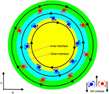
Since our interest is in KH instability of rotating SCDPs, we consider the specific cases of sharp vorticity patches: (i) single-circulation and (ii) multi-circulation vorticity shell profiles. Before proceeding with the direct assessment of the evolution of KH instability through the numerical results, it is useful to understand the process of formation of these vortices for sharp rotating flows through the schematic picture illustrated in figure 1. In this figure, multi-circulation vorticity profile has three different flows: core fluid rotates clockwise (yellow), inner shell rotates anticlockwise (cyan) and outer shell rotates clockwise (green). Each rotating flow is separated by a sharp interface; the fluid on either side rotates in counter directions. These counter-rotating flows create a region of high shear at each of the interfaces which immediately evolve into small co-rotating (like-sign) KH vortices. The direction of rotation of these vortices depends on the net relative rotation of alternate flows. At the inner interface, the core fluid (yellow) rotates clockwise while the inner-shell fluid (cyan) rotates anticlockwise, resulting in the KH vortices having anticlockwise rotation (blue-coloured vortices with blue curved arrows). Similarly, at the outer interface, the inner-shell fluid (cyan) rotates anticlockwise while the outer-shell fluid (green) rotates clockwise, resulting in clockwise-rotating KH vortices (red-coloured vortices with red curved arrows). In the case of further evolution, transport processes like merging and convection become important. When two co-rotating (like-sign) vortices are brought sufficiently close to each other, they start to rotate around one another and eventually merge to form a single vortex,while in convection the counter-rotating (unlike-sign) vortices propagate together as a single structure (dipole) to convect the fluid.
Formation of KH vortices at the circular sharp interfaces of core–shell flow regions (without any corresponding scale). The black circles with arrows in the flow regions indicate the direction of rotation. At the inner interface, the KH votices rotate anticlockwise (blue-coloured vortices with blue curved arrows), while at the outer interface they rotate clockwise (red-coloured vortices with red curved arrows).

Thus far, these appraisals are particularly true for an inviscid hydrodynamic fluid where no source term exists. Whereas an incompressible VE fluid, besides KH instability, would also support the TS waves that propagate through the medium at phase velocity $v_p= \sqrt {\eta /\tau _m}$ . Since TS waves have the same symmetry as that of their source structure, the TS waves emitted from each circular interface should be cylindrical in shape (Dharodi Reference Dharodi2020; Dharodi et al. Reference Dharodi, Kumar Tiwari and Das2014).
4.1.1. Evolution of single-circulation sharp-vorticity vortex
The velocity profile for the single-circulation sharp-vorticity vortex is given as follows:

The vorticity corresponding to the above velocity profile is given as

Here $|r|= {\sqrt {{({(x-x_c)/a})}^2+{({(y-y_c)/b})}^2}}$ , $a$
 and $b$
 are the major and minor axes, respectively, and $x_c$
 and $y_c$
 are the $x$
 and $y$
 coordinates of the centre of the vorticity profile. The vorticity will have a clockwise rotation if amplitude ${\phi _0}>0$
 , or have a anticlockwise rotation if ${\phi _0}<0$
 and have no rotation if ${\phi _0}=0$
 . We consider that the clockwise-rotating vorticity profile has circular symmetry with parameters $a=b=1$
 , amplitude ${\phi _0}=1$
 and sharp cutoff at radial distance $|r|=6$
 units away from the centre of the vortex $(0,0)$
 . This vorticity profile (yellow colour) is shown in figure 2(a) which has a circular interface with surrounding stagnant fluid at $t=0$
 . The simulation region is a square box of length 12${\rm \pi}$
 units.
Initial rotating sharp vorticity profiles at $t = 0$ to study the KH instability. The colour scale corresponding to a particular vorticity profile has been given in the following respective figure which shows its evolution. The simulation region is a square box of length 12${\rm \pi}$
 units for all these systems.

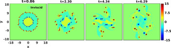
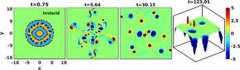
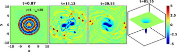
Figure 3 shows the time evolution of the vorticity profile given in figure 2(a) in the inviscid hydrodynamic fluid. The sharpness of the clockwise-rotating vorticity profile generates a strong rotational sheared flow. This sheared flow results in creation of small co-rotating (anticlockwise) KH vortices (dark-blue-coloured vortices) at the vorticity interface $|r|=6$ . These like-sign vortices start merging as rotation progresses that leads the fluid to evolve into an anisotropic isolated structure. In figure 4, where ${\eta }=5$
 and ${\tau _m}=20$
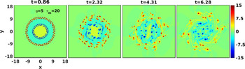
 , once the vortex begins to rotate, we observe a pair of ingoing and outgoing cylindrical shear waves from the interface along with these small like-sign KH vortices. During the evolution, it is observed that both the waves carry the like-sign vortices which interact with themselves in order to merge and also interplay with these waves as well. The fluid within the inner region ($|r| \leqslant 6$
 ) favours mixing due to the ingoing waves, while the stationary fluid in the outer region ($|r| \geqslant 6$
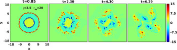
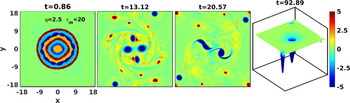
 ) becomes mixed due to the outgoing waves. Thus, the TS waves assist the process of fluid mixing by convecting it inside and outside the vortex structure. Unlike the inviscid case, here, the KH vortices are confined to the radial emitted waves. Since the wavefronts are cylindrical in shape, the interplay between waves and vortices leads the evolution of the VE fluid towards an isotropic structure. In figure 5, we have simulated another case of VE fluid which has less coupling strength ($\eta /\tau _m=0.125$
 ) with ${\eta }=2.5$
 and ${\tau _m}=20$
 . Unlike figure 4, since the TS waves are not strong enough to dominate over the KH instability, there is less confinement of KH vortices to the waves. This is evident from figure 5 where the evolution of the medium towards an isotropic structure and the mixing process are much slower in comparison with figure 4.
An inviscid hydrodynamic fluid. The time evolution of a sharp clockwise-rotating vorticity which has a circular interface with surrounding stagnant fluid. The sharpness of the vorticity profile generates small KH vortices at the interface that results in a anisotropic isolated structure.

Viscoelastic fluid with coupling parameters ${\eta }=5$ and ${\tau _m}=20$
 . The time evolution of a sharp rotating vorticity which has a circular interface with surrounding stagnant fluid. The sharpness of the vorticity profile generates small KH vortices at the interface along with a pair of ingoing and outgoing wavefronts of TS waves that assist in fluid mixing by convecting it inside and outside the vortex structure.

The time evolution of a sharp rotating vorticity in VE fluid with coupling parameters ${\eta }=2.5$ and ${\tau _m}=20$
 . Due to less coupling strength, the evolution of the medium towards an isotropic structure and the mixing process are much slower in comparison with figure 4.

In conclusion, as a result of greater coupling strength or stronger TS wave, the medium evolution attempts to realize radial symmetry and shows better mixing. The mixing is found to be minimal in inviscid fluid.
The single-circulation sharp profile carries single types of anticlockwise-rotating KH vortices across its only interface. While a multi-circulation profile with two or more interfaces produces clockwise as well as anticlockwise KH vortices. Thus, in the multi-circulation case, apart from merging between like-sign vortices, the propagation of unlike-sign vortices as a dipolar structure also becomes important which can assist in increasing the spatial domain of mixing fluids.
4.1.2. Multi-circulation vorticity shell profile
Here, we first consider the simplest case of multiple shells of vorticity having two flows: inner core flow and a outer shell flow, both flows having reversal circulation. The velocity profile for this configuration is given as follows:

The vorticity corresponding to the above velocity profile is given as

With the parameter $\phi _0=1$ , we consider both flows to rotate with equal rotation rates and in opposite directions (figure 2b). Figure 6 shows the evolution of this vorticity profile for an inviscid fluid. At the inner interface, the KH vortices rotate anticlockwise (blue-coloured vortices), while at the outer interface they rotate clockwise (red-coloured vortices). As time goes on, merging between like-sign vortices takes place at both interfaces, and simultaneously growing closeness between both interfaces due to the radial gradient in vorticity resulting in interactions between the counter-rotating (red–blue) vortices as well. These counter-rotating vortices result in the formation of propagating dipolar structures which help to convect the fluid across a wider domain than the single interface (which only favours the merging process).
An inviscid hydrodynamic fluid. Evolution of vorticity having two circular sharp flows, inner core and outer shell flows have reversal circulation, in time generates small KH vortices at each interface that results in an anisotropic isolated structure.

In figure 7, we observe that a pair of ingoing and outgoing wavefronts emanates from each of the two sharp interfaces of the vortex structure along with KH vortices (see the first panel). It is observed that both wavefronts at the inner interface carry the blue-coloured (rotating anticlockwise) vortices, while at the outer interface they carry red-coloured (rotating clockwise) vortices. During the emission of these shear waves, like-sign vortices interact with themselves in order to merge. The stagnant fluid in the outermost region ($|r| \geqslant 10$ ) undergoes mixing due to the outgoing wave from the outermost interface at 10, while the innermost vortex region undergoes mixing due to the ingoing wave emanating from the sharp interface located at 5. Interestingly, the vortex region confined within the two sharp interfaces ($5 <|r|\leqslant 10$
 ) undergoes mixing due to the ingoing wave from the outermost interface and the outgoing wave from the innermost interface. This region is probably a convection-dominating region due to the higher possibility of formation of propagating dipolar structures. As a result of multiple interaction processes, the mixing becomes fast and efficient compared with the cases discussed so far. Next, we consider another VE fluid in figure 8 having lower coupling strength, i.e. ${\eta }=2.5, {\tau _m}=20, v_p=0.35$
 . It is observed that at each time step the spatial confinement of this medium is lower than in figure 7. Moreover, the comparison manifests that the mixing and evolution symmetry of a medium are proportional to the coupling strength of that medium as observed for earlier cases.
Viscoelastic fluid with coupling parameters $\eta =5$ and $\tau _m=20$
 . The time evolution of vorticity having two circular sharp interfaces, inner core and outer shell have reversal circulation, generates small KH vortices at each interface along with a pair of ingoing and outgoing TS wavefronts that results in fluid mixing by convecting it inside and outside the vortex structure.

Viscoelastic fluid with coupling parameters ${\eta }=2.5$ and ${\tau _m}=20$
 . The time evolution of vorticity having two circular sharp interfaces, both having reversal circulation. Due to the lower coupling strength, the spatial confinement of this medium is lower than in figure 7.

Next, in order to make a better comparative numerical analysis of the mixing rate, we consider a more complex scenario of multiple circulations (each consecutive one having a reversal in its circulation) having the following velocity flow profile:

The vorticity corresponding to the above velocity profile is given as

For the parameter $\phi _0=1$ , the initial vorticity profile is shown in figure 2(c). The complexity of this motion of multi-circulation structure is evident from figure 9 for inviscid fluid. In the initial time period, the vortices of KH instability develop across the interface of each shell. At intermediate time range, this evolution provides a complete picture of a turbulent flow throughout the entire system which is a collection of several small symmetric and non-symmetric vortices. The transport phenomena like merging between two co-rotating vortices, convection due to the evolution of dipolar (two counter-rotating) vortices, collision between these dipolar vortices and also the formation and evolution of tripolar structures become more frequent than for the cases discussed above.
Figure 10 presents the evolution of the same initial profile (figure 9) of vorticity for VE fluid with coupling parameters ${\eta }=5$
 , ${\tau _m}=20$
 . From the comparative observations between figures 9 and 10, it is interesting to notice that the presence of TS waves leads to the relaxing of the turbulent medium to a single vortex faster than in inviscid fluid. In figure 11 (${\eta }=2.5, {\tau _m}=20, v_p=0.35$
 ), since the TS waves are weaker than in figure 10, the less spatial confinement of the turbulent medium results in a slower merging process, due to which the relaxation time of the medium becomes longer.
An inviscid hydrodynamic fluid. The time evolution of multi-circulation vorticity profile, each consecutive one having a reversal in its circulation, generates small KH vortices at each interface. This evolution provides a complete picture of a turbulent flow which is a collection of various kind of vortices, and exhibits transport properties like convection and merging.

The time evolution of multi-circulation vorticity profile in VE fluid with ${\eta }=5$ and ${\tau _m}=20$
 . The strong interaction between KH vortices and TS waves results in relaxing of the medium into a single vortex faster than for inviscid fluid.

The time evolution of multi-circulation vorticity profile in VE fluid with ${\eta }=2.5$ and ${\tau _m}=20$
 . Since the TS waves are weaker than in figure 10, the relaxation time of the medium becomes longer.

A comparison of figures 10 and 11 clearly displays these observations.
4.2. Transport of tracer particles
In § 2 we have stated that tracer particles with very low inertia follow the flow passively, while particles with very high inertia will remain almost unaffected by the medium fluctuations. Between these two limits particles show the strongest response to the medium fluctuations. Simulations are performed for all three types of inertial particles: very low ($\tau _s=0.05$ ), intermediate ($\tau _s=1$
 ) and very high ($\tau _s=50$
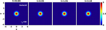
 ) inertia. To observe the exclusive effect of inertia, we transport these particles through a similar smooth rotating vorticity vortex in an inviscid fluid. An inviscid fluid has no source term which favours the emission of TS waves or dissipative term like viscosity. Also, we choose a smooth rotating vorticity vortex which does not satisfy the KH destabilization condition anywhere in the vorticity patch. The equation of such smooth rotating vorticity is given as

The evolution of the same structure given by (4.7) for ${a_c}=1.0$ , ${\varOmega _0}=5$
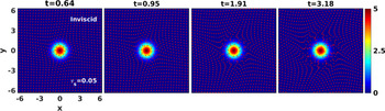
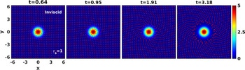
 in an inviscid fluid is shown in figures 12, 13 and 14. From these figures it is clear that the rotating vortex keeps rotating without any change. Now, in order to see the response of tracer particles, initially $(t=0)$
 , we distribute 900 inertial particles (shown by red dots) homogeneously throughout the domain. From figure 12, it is clear that low-inertia particles ($\tau _s=0.05$
 ) follow the dynamics along the rotating vortex, and the particles with higher inertia ($\tau _s= 50$
 ; figure 13) show negligible response to the vorticity gradient. In comparison with previous cases (figures 12 and 13), figure 14 shows that the particles with intermediate value of $\tau _s=1$
 encounter a significant outward push. This is because the particle and fluid time scales are comparable which results in the particles experiencing a notable centrifugal force due to vorticity gradient. Since the inertial particles are pushed away from regions where the flow is strong enough, these particles accumulate in strain-dominated regions. Thus, particles tend to leave regions of high vorticity and cluster into regions of high strain (Ravichandran, Deepu & Govindarajan Reference Ravichandran, Deepu and Govindarajan2017). Note that we have simulated a range of intermediate-inertia particles, and observed the same effect with varying outward push.
An inviscid hydrodynamic fluid carries tracer particles shown as red dots. The low-inertia tracers ($\tau _s=0.05$ ) follow the dynamics along the smooth rotating vortex.

An inviscid hydrodynamic fluid carries tracer particles shown as red dots. The high-inertia tracers ($\tau _s=50$ ) show negligible response to the rotating vortex.

An inviscid hydrodynamic fluid carries tracer particles shown by red dots. Smooth rotating vorticity vortex with tracers having intermediate inertia, i.e $\tau _s=1$ , showing strong response to the vorticity gradient. The particles are pushed away where the flow is strong enough and accumulate in a strain-dominated region.

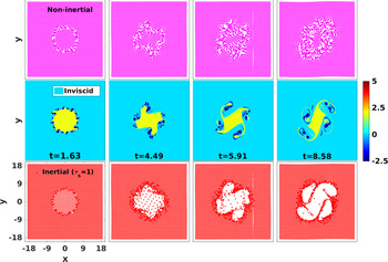
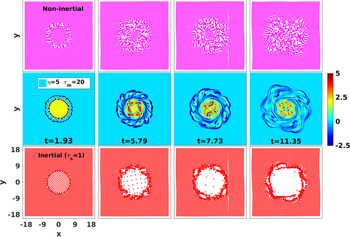
With the identification of intermediate-inertia particles and understanding of their evolution, next we compare the evolution of intermediate-inertia particles (typically, $\tau _s=1$ ) with non-inertial particles for the inviscid hydrodynamic and VE ($\eta =5$
 , $\tau _m=20$
 ) fluids in figures 15 and 16, respectively. For this, we choose a sharp rotating vorticity profile which is given by (4.2). The middle rows in figures 15 and 16 represent the time evolution of this profile for inviscid and VE fluids, respectively. As the sharp vortex starts to rotate, it produces larger strain (deformation) in the medium along the interface that results in the formation of KH instability. The evolution of this rotor has already been discussed in § 4.1 for inviscid fluid in figure 3 and for VE fluid in figure 4. Initially $(t=0)$
 , here, we distribute 3600 tracer particles homogeneously throughout these fluids. In both figures 15 and 16, the first and third rows visualize the distribution of non-inertial particles (shown by magenta dots) and inertial particles (shown by red dots), respectively, advected by the respective fluid flow shown in the middle row. The accumulation of non-inertial particles is observed in rotation-dominated regions over the vortex structures, while the inertial particles accumulate in strain-dominated regions along the interfaces. This accumulation process leads to the spatial inhomogeneous distribution of particles. This inhomogeneous distribution of the particles is known as clustering or preferential concentration. Clustering is well studied in the case of inertial particles (Maxey Reference Maxey1987; Squires & Eaton Reference Squires and Eaton1991; Fessler et al. Reference Fessler, Kulick and Eaton1994; Balkovsky et al. Reference Balkovsky, Falkovich and Fouxon2001; Falkovich, Fouxon & Stepanov Reference Falkovich, Fouxon and Stepanov2002; Goto & Vassilicos Reference Goto and Vassilicos2006; Petersen, Baker & Coletti Reference Petersen, Baker and Coletti2019; Oka & Goto Reference Oka and Goto2021), and several studies are available for non-inertial particles (Drótos et al. Reference Drótos, Monroy, Hernández-García and López2019).
An inviscid hydrodynamic fluid advecting tracer particles. First and third rows show the temporal and spatial distribution of non-inertial particles (shown by magenta dots) and inertial particles ($\tau _s=1$ , shown by red dots), respectively, corresponding to the sharp vorticity profile evolution shown in the second row.

Viscoelastic fluid with coupling parameters ${\eta }=5$ and ${\tau _m}=20$
 advecting tracer particles. First and third rows show the spatiotemporal distribution of non-inertial particles (shown by magenta dots) and inertial particles ($\tau _s=1$
 , shown by red dots), respectively, corresponding to the sharp vorticity profile evolution given in the second row.

In real flows the tracer particles always have some inertial value, so we compute the ensemble-averaged MSD of intermediate-inertia particles to analyse the diffusion of particles in the carrier VE fluid. This diffusion of particles is associated with the mixing of the fluid. For this, we advect the inertial particles having $\tau _s=1$ using the sharp rotating flows discussed above: inviscid fluid in figure 3/figure 15, VE fluid with $\eta =5$
 , $\tau _m=20$
 in figure 4/figure 16 and another VE fluid with $\eta =2.5$
 , $\tau _m=20$
 in figure 5. Initially ($t=0$
 ), we disperse 3600 tracer particles homogeneously in these fluids. Figure 17(a) compares the ensemble-averaged MSD values of inertial particles of $\tau _s=1$
 for all three types of fluids. The evolution of MSD occurs in three stages. Initially (here, $0\geqslant t\approx 1$
 ), inertial particles do not respond until their time scale (here, $\tau _s=1$
 ) is less than the fluid time scale or the Stokes number (St) is less than unity. During the second stage, the particles start to respond to the flow ($1\geqslant t\leqslant 3.8$
 ), and the slopes grow at almost the same rate for all fluids. In the final stage ($t\geqslant 3.8$
 ), the slope shows a larger value for a higher coupling strength and it is minimal for inviscid fluid. The slope of MSD versus time is proportional to the diffusion coefficient of the tracer particles. Thus, a larger time–MSD slope means the carrier fluid shows a better mixing performance. Thus, this result is found consistent with our earlier observations made from the comparative analysis of pictorial evolution of vorticities in figures 3, 4 and 5. In order to substantiate these observations we further compute the MSD of tracers with $\tau _s=0.5$
 (figure 17b) for all three flows under the same flow conditions. From the plot, again the diffusion of particles increases with coupling strength. It should be noted that the MSD has been calculated up to time before hitting the flow to the boundaries.
The MSD as function of time for tracing particles. The sharp rotating vorticity advecting the particles with (a) $\tau _s=1$ and (b) $\tau _s=0.5$
 . At later time, the MSD is proportional to the coupling strength.

In the present work, although we have undertaken the simplest tracer model and preliminary investigation of tracer distribution (cluster formation) and their transport property (MSD), it is worth attempting as a foundation for future study.
5. Summary and conclusion
In this paper, we numerically explore the KH instability for a two-dimensional rotating SCDP under the formalism of the GHTT fluid model. This model treats the SCDP as a VE fluid. Here, we consider the specific cases of vorticity with abrupt radial changes, in particular: single-circulation and multi-circulation vorticity shell profiles. We observe the KH instability in the form of small vortices at each interface along with a pair of ingoing and outgoing wavefronts of TS waves. The interactions between KH vortices and with TS waves govern the mixing which has been quantified using a passive tracer particle simulation. The advection of tracers with the flow has been noticed. Some main observations are as follows.
(i) The interplay between the TS waves and interacting KH vortices results in better mixing of VE fluids than standard hydrodynamic fluids where only the interaction between KH vortices happens.
(ii) By adjusting the coupling strength parameter (ratio $\eta /\tau _m$
 ) which usually represents the strength of viscoelasticity of the medium, one can control the evolution of KH instability that results in control over the transport properties like mixing and diffusion.
(iii) The GHD model especially developed for the study of SCDPs is extended to include the transport of passive Lagrangian inertial and non-inertial tracer particles. This extended model is referred to as the GHTT model.
(iv) We observe that the diffusion of intermediate-inertia tracer particles in VE fluids is proportional to the coupling strength. It is least for an inviscid fluid.
(v) From the multi-circulation vortex profiles, we found that the relaxation rate of a turbulent medium increases with increasing coupling strength.

The particle tracking model appears to be a suitable diagnostic for understanding the associated mixing in a fluid through the diffusion process, and nonlinear dust fluid dynamics through the clustering of a tracers. In the present paper, we just discuss the preliminary simulations for tracers which are based on first-order schemes. To advance the tracers we use a first-order Runge–Kutta scheme, and for the velocity the first-order interpolation scheme. Further improvisations of this model would be to include higher-order schemes, finite-size tracers, other forces, e.g. gravity, interparticle interactions, feedback from tracers to carrier fluid, etc. These improvisations would be extremely fruitful which are left to future work. An experimental research effort is required in order to validate this numerical work. We believe our results can inspire future experiments. Some experiments, in order to create rotating vortex flows in dusty plasmas with external rotating electric fields and/or magnetic fields, have been performed (Danielson & Surko Reference Danielson and Surko2006; Nosenko et al. Reference Nosenko, Ivlev, Zhdanov, Fink and Morfill2009; Wörner et al. Reference Wörner, Nosenko, Ivlev, Zhdanov, Thomas, Morfill, Kroll, Schablinski and Block2011; Karasev et al. Reference Karasev, Dzlieva, Pavlov, Novikov and Maiorov2017). Keeping in view the present study, experimentalists will have to delimit the externally driving/rotating forces in order to produce radially confined sharp rotation flows in the medium.
Acknowledgements
Editor Edward Thomas, Jr. thanks the referees for their advice in evaluating this article.
Declaration of interests
The authors report no conflict of interest.