I. INTRODUCTION
The increase in fuel demand and the consequently atmospheric pollution growth has induced lower permissible sulfur content in the environmental regulations. Industrially to reach the maximum content of 10 ppm of sulfur on diesel fuels, a catalytic process with high hydrogen pressure is required,Reference Song1 being this hydrotreating process expensive and of severe conditions. Sulfur removal becomes more complicated due to the high refractory sulfur content of some crude oils such as benzothiophenes and alkyldibenzothiophenes,Reference Song1 and even more difficult using the same catalyst used since World War I, which normally consists of molybdenum and tungsten sulfides, promoted with elements like nickel or cobalt over alumina as support.Reference Chianelli, Berhault and Torres2
Nowadays, commercial unsupported catalysts such as NEBULA meet these regulations, but with high costsReference Mendoza-Nieto, Robles-Méndez and Klimova3; since this catalyst is a trimetallic (NiMoW), it has high density, low surface area, and high cost. In consequence, many of the new research is focused on the development of cheaper catalysts with high surface areas and low and well-dispersed metal loadings. An attractive alternative is the use of the SiO2-based high surface area mesoporous materials, which offers more than 2-fold the surface area of commercial alumina and allows the possibility to disperse highly reactive sites. Due to the mesoporous structure of these supports, active sites will be available even for refractory sulfur-containing molecules from fuels during the reaction and in higher concentration per volume than alumina catalyst could offer, and without the high cost that unsupported catalyst presents since there is only a fraction of metal content. In this context, despite the difficulties in obtaining highly dispersed catalysts, the most common and simple method is the incipient impregnation.Reference Vandillen, Terorde, Lensveld, Geus and Debjong4,Reference Munnik, de Jongh and de Jong5 Although the implementation is simple, the phenomenon involved is complex since redistribution of active phase occurs during drying owing to the limited support–metal interaction, and this migration is even more important as the surface area increases. Vandillen et al.Reference Vandillen, Terorde, Lensveld, Geus and Debjong4 studied the viscosity effect of the chelating agent in the impregnation method during drying and found a delay between the drying of different aqueous chelated metal complexes over MCM-41 as support. This well-ordered mesoporous silica has received more attention due to the characteristics that possess, like high thermal stability and high porosity, similar materials such as SBA-15 and KIT-6 have been studied as supports for a different type of catalyst. The main challenge to the use of mesoporous SiO2 materials is the low dispersion obtained of active species, due to the lack of acidity on the surface. A way to remedy the lack of acidity is the use of dopants to improve the adherence of the active phase on the SiO2 surface, some of the most used elements for this purpose are P, B, Al, Ti, F, Zn, La, V, Ga, and Mg. In addition to the good dispersion of the active phase and large surface area, it is necessary to attain a special configuration of the active species loaded on the catalyst.Reference Chianelli, Berhault and Torres2 In the hydrodesulfurization field, it is accepted that MoS2 forms a hexagonal microstructure surrounded by Ni atoms located on the rim and edgesReference Shimizu, Hiroshima, Honma, Mochizuki and Yamada6,Reference Coulier7 (CoMoS or NiMoS model), which allows higher activities. Under normal conditions, sulfidation of the Ni promoter begins at room temperature while the molybdenum precursor begins at 75 °C; this leads the formation of isolated bulk NiSx crystals, then when temperature reaches 75 °C, Mo starts to react, thus only a fraction of Ni is available to form the NiMoS highly active phase.Reference Vogelaar8 One way to overcome this problem is to employ chelating agents, and these molecules contain two or more potential electron-pair donor atomsReference Vandillen, Terorde, Lensveld, Geus and Debjong4 that can act as a ligandReference Shimizu, Hiroshima, Honma, Mochizuki and Yamada6,Reference Repo, Warchoł, Bhatnagar, Mudhoo and Sillanpää9–Reference Li, Li, Chu, Liu and Nie12 (Lewis base) which attaches itself to a metal ion (Lewis acid), through a Lewis acid–base reaction. Rana et al.Reference Rana, Ramirez, Gutierrezalejandre, Ancheyta, Cedeno and Maity13 studied the effect of EDTA as a chelating agent using the pH of 9 to form a stable complex with cobalt, and then probe the delay of sulfidation by the thermoprogrammed sulfidation pattern. Huadong Wu et al.Reference Wu, Duan, Zhao, Qi, Li, Liu, Jiang, Liu, Wei and Zhang14 tested a NiMo catalyst over KIT-6 using different concentrations of citric acid (CA) to tune sulfidation, trying to increase dispersion degree, and the results shown the higher formation of NiMoS phase for higher content of CA. Mazoyer et al.Reference Mazoyer, Geantet, Diehl, Loridant and Lacroix15 also studied chelating agents and compared the effect of diA-EDTA (diammonium salt of ethylenediaminetetraacetate) calcined or uncalcined and found out a decrease in the formation of CoMoO4 which is not a good promoter for CoMoS-type structure formation, demonstrating thus that diA-EDTA promotes the CoMoS phase. The work of Al-Dalama and StanislausReference Al-Dalama and Stanislaus16 shown through thermoprogrammed reduction (TPR) patterns for calcined and uncalcined Ni/SiO2–Al2O3 that the effect of EDTA is clear and consists on the formation of Ni[EDTA]2− complex, which is more stable than Ni(NO3)2, which causes a better-sulfided catalyst. In the present work, the influence of chelating agents in the drying step and in sulfidation is studied, and the agents used were citric acidReference Eduardo, Vargas and Heredia17–Reference Fan, Xiao, Shi, Liu, Qian, Wang, Gong and Bao20 and ethylenediaminetetraacetic acid (EDTA),Reference Vandillen, Terorde, Lensveld, Geus and Debjong4,Reference Fujikawa, Kimura, Kiriyama and Hagiwara21,Reference Escobar, Barrera, de los Reyes, Toledo, Santes and Colín22 which are the most used. Based on the functional group that polyacrylic acidReference Soni, Rana, Sinha, Bhaumik, Nandi, Kumar and Dhar24 have, this polymer could be a good polymeric chelating agent since one molecule of a proper polymer can act as a trap for several nickel atoms (depending on the molecule length) and also increase viscosity avoiding thus redispersion of the active phase, then a highly dispersed and active supported catalyst can be obtained; in the work of Roma-Luciow et al.,Reference Roma-Luciow, Sarraf and Morcellet23 the stability constants of the complex between PAA and different ions such as nickel and cobalt were determined.
Therefore, three chelating agents were used in the synthesis of surface-modified NiMo catalysts (16 wt% of metal loadings) supported on KIT-6 modified with alumina, with different heat treatments or activation methods and their performance in the HDS of a model molecule such as DBT was studied. The effect of the chelating agent in the sulfidation of Ni can be seen as a restraint in sulfidation kinetics, leading to the higher availability of Ni for the NiMoS phase formation during the Mo sulfidation.
II. EXPERIMENTAL SECTION
A. Support synthesis and surface modification
Mesoporous silica (KIT-6) was prepared following the modified methodology of Soni et al.Reference Roma-Luciow, Sarraf and Morcellet23 using a triblock copolymer (pluronic P 123 from Sigma-Aldrich, St. Louis, Missouri) as the structure directing agent. On a typical synthesis, Pluronic (4 mmol/L) is dissolved in a mixture of distilled water (47 mol/L) and hydrochloric acid (465 mmol/L, J. T. Baker, Mexico City, Mexico; 36.5–38%), later butanol (315 mmol/L, Sigma-Aldrich 99.8%) is added under constant stirring at 35 °C. After 1 h, tetraethyl orthosilicate (240 mmol/L TEOS, Sigma-Aldrich 98%) was added dropwise under continuous stirring for 2 h at 35 °C. The solution was then transferred to a Teflon autoclave heated at 120 °C for 24 h. Finally, the solid was filtered, washed with a mixture of ethanol (HYCEL, Mexico City, Mexico; 96%) and hydrochloric acid and dried, followed by calcination at 550 °C to remove the template. The surface of the support was modified by pore volume impregnation with an ultrasonic probe to obtain KIT-6 with 10% atom of aluminum, employing a solution containing aluminum tri-sec-butoxide (aluminum tri-sec-butoxide, Aldrich 97%) (0.45 g aluminum tri-sec-butoxide/g of support) and 2-propanol followed by drying at 60 °C, and calcination at 550 °C.
B. Catalyst preparation
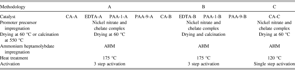
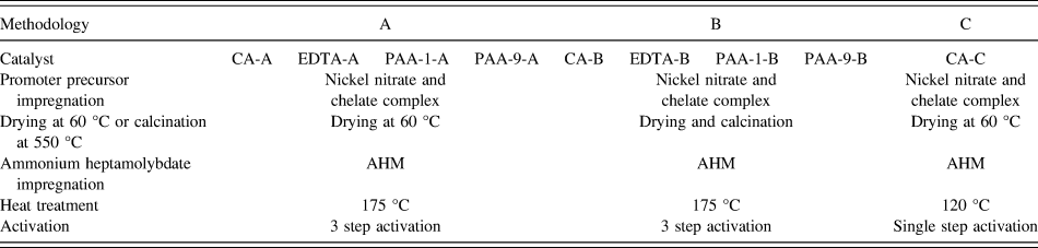
The chelating agents used were citric acid (Fisher, Waltham, Massachusetts; 99.7% CA), ethylenediaminetetraacetic acid disodium salt dihydrate (J. T. Baker 99.5% EDTA), and two polymeric chelating agents based on polyacrylic acid. The polymeric materials were synthesized to obtain molecular weights of 1000 g/mol (PAA-1), and 9000 g/mol (PAA-9). The catalysts were synthesized by consecutive pore volume impregnations; for all catalysts, the impregnations were made as follows: Nickel nitrate > chelating agent > ammonium heptamolybdate (NNi > Ch > AHM). After chelating agent was added, the Ni-chelating agent complex was formed with a stoichiometric proportion of ammonium hydroxide (Sigma-Aldrich, 28–30%) and nickel nitrate (Ni(NO3)2·6H2O Acros Organics, 99%),Reference Rana, Ramirez, Gutierrezalejandre, Ancheyta, Cedeno and Maity13,Reference Soni, Rana, Sinha, Bhaumik, Nandi, Kumar and Dhar24,Reference Chaberek and Martell25 and pH measurements were not possible to make because of the nature of pore volume impregnation. Subsequently, ammonium heptamolybdate [(NH4)6MoO24·4H2O, Sigma-Aldrich 81–83% MoO3 basis] was impregnated in the necessary amount to obtain a 16% wt of metals with a ratio of Ni/Ni + Mo = 0.50. Methodology A consists in the impregnation of nickel and complex formation, followed by drying, then the AHM addition and drying at 175 °C, and finally a three-step activation; in these materials, the purpose is to maintain the chelating agent until activation to obtain a greater proportion of the NiMoS phase. Methodology B consists on the impregnation in the following order NNi > Ch > drying and calcination > AHM, and calcination was carried out to eliminate the chelating agent to determine the effect of viscosity in the drying step to avoid redispersion of metals; at last, the three-step activation was performed. In methodology C, the impregnation order was as follows: NNi > Ch > AHM and drying at 120 °C; then for these materials, the activation was changed to a traditional single step activation to compare the effect on the activity of this stage between the two sulfidations. The three-step activation (methodology A and methodology B) consists of a sulforeductive atmosphere of H2S/H2 (total gas flow of 45 mL/min, 15% of H2S) starting at 25 °C for 3 h and later an abrupt change of temperature to 300 °C (100 °C/min heating rate) for 3 h; passing that time, the atmosphere was changed to H2/N2(total gas flow of 50 mL/min, 10% of H2) with an increasing temperature of 4°/min until 400 °C for 2 h. The single-step activation (Methodology C) consists in a sulforeductive atmosphere with an increasing ramp of 4 °C/min until 400 °C for 4 h (total gas flow of 67 mL/min, 15% H2S). After activation, all powders were kept in a sealed bottle under a nitrogen atmosphere to avoid oxidation. The conditions of catalysts synthesis is summarized in Table I
Summary of the condition in catalysts synthesis.
.
C. Materials characterization
The catalyst powders (after sulfidation) were characterized by the BET method from nitrogen physisorption measurements performed in a NOVA Quantachrome 4200 series (Anton Paar, Graz, Austria). Prior to the analysis, the powder was outgassed at 300 °C for 4 h. Thermogravimetric analysis was performed on a TA instrument (New Castle, Delaware) under a nitrogen atmosphere, and X-ray diffractograms were obtained using a PanalyticalXpert’PRO diffractometer (Anton Paar, Graz, Austria) operated at 40 kV and 35 mA, with radiation of Cu Kα, λ = 1.541874 Å; from 10 to 80° using a step size of 0.05° (2θ) and 100 s as the count time per step. High-resolution transmission electron micrographs (HRTEM) and energy dispersive X-ray elemental analyses were obtained using a field emission TEM JEOL-JEM2200 (JEOL, Tokyo, Japan); prior to the analysis, the materials were ultrasonically dispersed in isopropanol, and then a drop from the solution was applied on a copper–carbon grid.
D. Catalytic hydrodesulphurization activity test
The catalytic performance was carried out in a 1 L batch reactor from Parr (Moline, Illinois). The initial concentration of sulfur in DBT (dibenzothiophene, 98% Acros Organics) on 150 mL of decalin (decahydronaphthalene, mixture of cis + trans, Sigma-Aldrich 98%) as a solvent was 4250 ppm. A sample of 0.5 g of the catalyst was transferred to the reactor, then the reaction was carried out at 350 °C and a hydrogen pressure of 3.4 MPa. The samples were taken every 30 min by 5 h. The collected samples were analyzed by gas chromatography on Perkin Elmer equipment Claurus 500 (Waltham, Massachusetts) of 12 ft long and diameter of 1/8 in packed column OV-17, and the sulfur concentration was determined with an FID detector. The rate constant was calculated with the L–H (Langmuir–Hinshelwood) equation assuming a pseudo-zero-order reaction.
III. RESULTS
A. Textural analysis
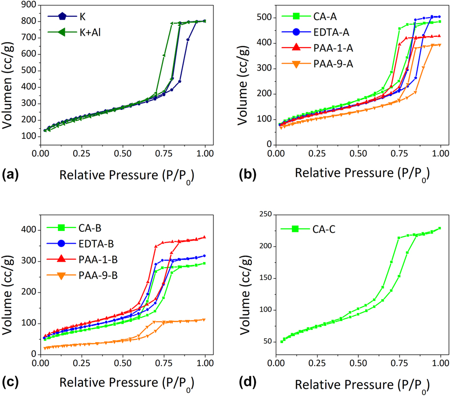
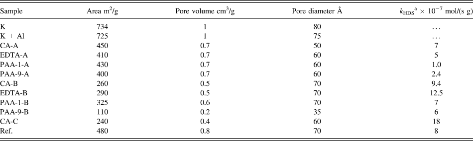
The nitrogen physisorption isotherms from the supports (K and K + Al representing the mesoporous silica with and without alumina surface modification, respectively) and catalysts are presented in Fig. 1. In Fig. 1 (a) are shown the samples K and K + Al, according to IUPAC classification,Reference Peña, Valencia and Klimova26 materials present a type IV isotherm characteristic of porous materials, and H1 hysteresis loop distinctive for pores of cylindrical body the same type of isotherm and hysteresis as the obtain in the work of Jo, Kim and Ryoo,Reference Thommes, Kaneko, Neimark, Olivier, Rodriguez-Reinoso, Rouquerol and Sing27 the structure remains despite the addition of alumina and high-temperature calcination, pure mesoporous silica has 734 m2/g of superficial area, pore volume of 1 cm3/g and 80 Å of pore diameter, and after the addition of alumina the textural properties were maintained 725 m2/g, 1 cm3/g, and 75 Å of surface area, pore volume and pore diameter, respectively.
BET isotherm for the (a) support with and without modification, (b) catalyst for methodology A, (c) methodology B, (d) and methodology C.
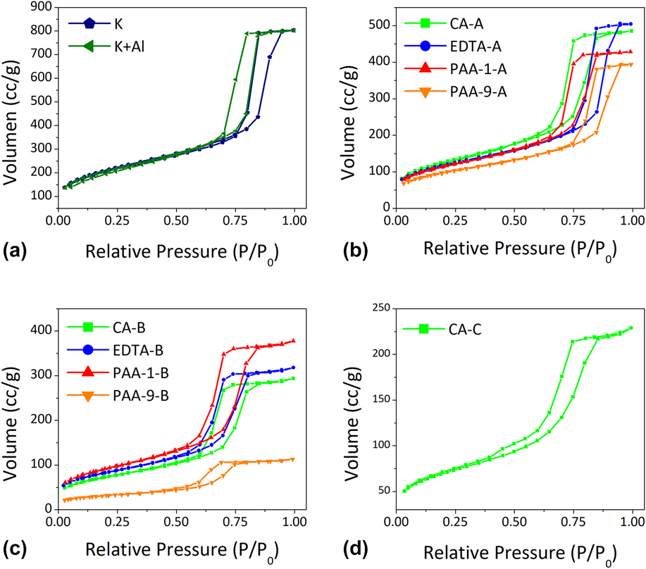
As can be seen in Fig. 1(b), the catalyst from methodology A presented a type IV isotherm and an H1 hysteresis loop typical of porous materials and cylindrical pore shape. After the addition of metals and activation, the textural properties decreased notably, and the values obtained are presented in Table II. Catalysts prepared with methodology A after three-step activation shown a decrease in surface area as the chelating agent molecular weight increased, and high carbon residues are left after activation, the obtained surface areas of the samples were around 400 m2/g, pore volumes of 0.7 cm3/g, and pore diameter of 70 Å. Figure 1(c) shows the isotherms for catalyst synthesized with methodology B, which was calcined before the addition of AHM and using three-step activation. This material presented lower textural properties than that obtained for A methodology materials. The surface area difference could be attributed to the calcination step, and the surface areas obtained are between 100 and 300 m2/g. Finally, the sample in Fig. 1(d) shows the catalyst synthesized with C methodology, which consists in no calcination and a slow heating rate. The resulting catalyst presented 240 m2/g, 0.4 cm3/g, and 60 Å, to superficial area, pore volume, and diameter, respectively. To explain the difference in the surface area, two aspects are considered: first is related to the sintering of the oxide during calcination and second to the molecular weight of the polymeric chelating agent; the latter is validated since all catalysts prepared with citric acid (considerably lower molecular weight) presented the highest surface areas from the series with or without calcination, and a similar trend for pore volume and pore diameter is observed. In general, when a calcination stage is not included (methodology A), the textural properties remain close regardless of the type of the chelating agent used, except when the molecular weight rises considerably.
Textural and catalytic properties of support and catalysts.
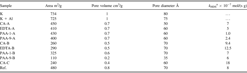
a Determined at DBT conversion of 5%.
B. X-ray diffraction
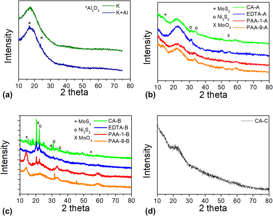
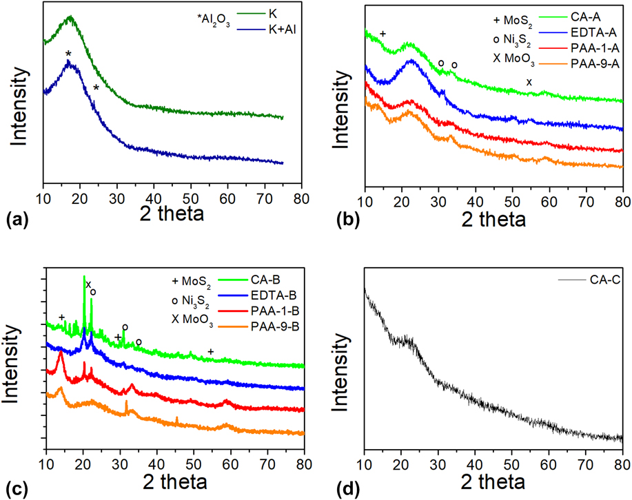
Representative diffraction patterns from the supports and catalysts are shown in Fig. 2. In both supports, a wide signal between 14° and 35° typically attributed to the amorphous silica can be observed, while a small signal at 22° could be attributed to Al2O3 (00-031-0026) from the K + Al pattern [Fig. 2(a)]. Moreover, the catalysts show signals [Fig. 2(b)] at 14, 29, 60° that correspond to the planes (002), (100), (110) from MoS2 phase (00-087-2416), respectively. The calculated crystal stack using (002) MoS2 plane and Scherrer equation and using an interplanar distance of 6.17 Å are 3, 4, 7.5, 7 nm for CA-B, EDTA-B, PAA-1, and PAA-9-B, respectively. The signals at 23, 28, 40° that could be attributed to Ni3S2 phase (00-002-0772) also be observed. In general, the higher molecular weight chelating agent (PAA-9) showed a lower degree of crystallinity, which can be attributed to the high carbon content remaining on the surface after activation step. Finally, the signal at 20° could be related to MoO3 (00-021-0569), which is more intense as the molecular weight of the chelating agent decreases. This can be explained because the metals are more susceptible to contact with oxygen in the materials synthesized with chelating agents of smaller molecules; moreover, this is not observed in the catalyst obtained by chelation with PAA-9. To the CA-C catalyst, the pattern obtained [Fig. 2(c)] shows only a wide peak at 22° from amorphous silica, with no evidence of another crystalline phase, or probably, too small crystals are formed, which do not show a significant signal for this characterization technique. Due to the lack of signals related to MoS2 slabs, the calculation of crystal stacks was not possible.
X-Ray patterns of the (a) KIT-6 with and without Al modification, (b) catalyst with chelating agents synthesized with methodology A, (c) catalyst with chelating agent and methodology B, and (d) catalyst with chelating agent and methodology C.
C. Transmission electron microscopy
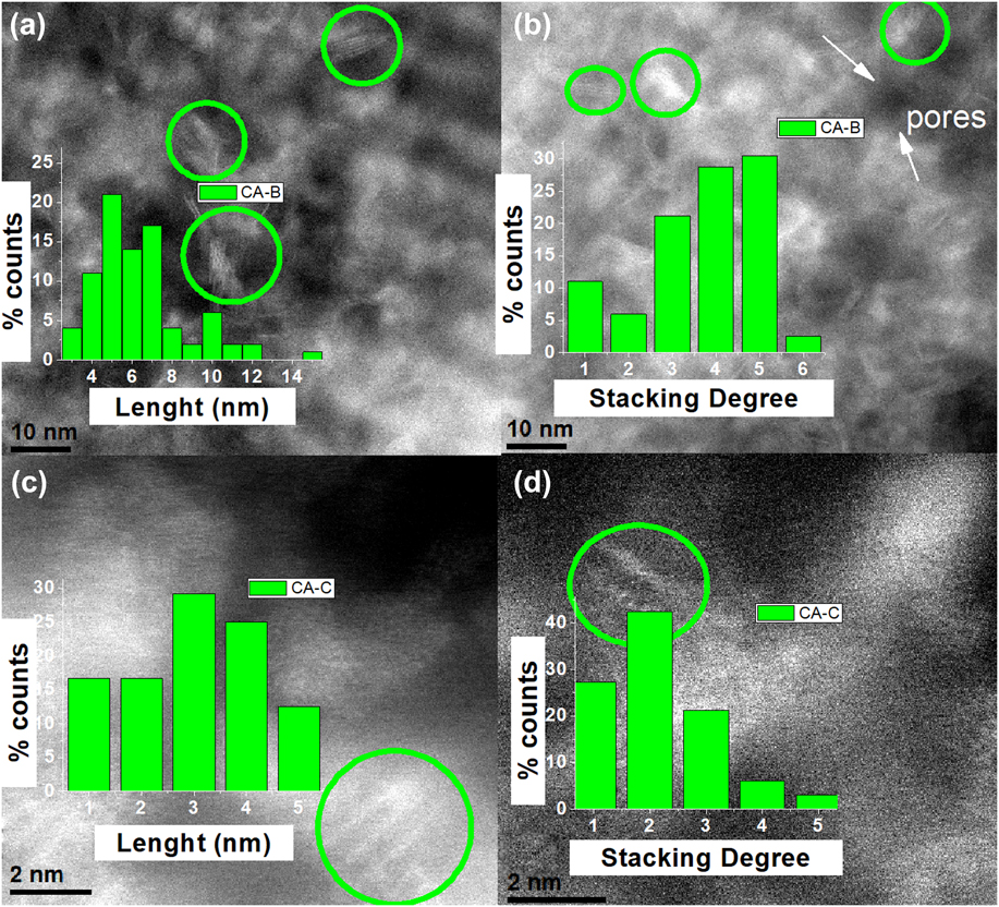
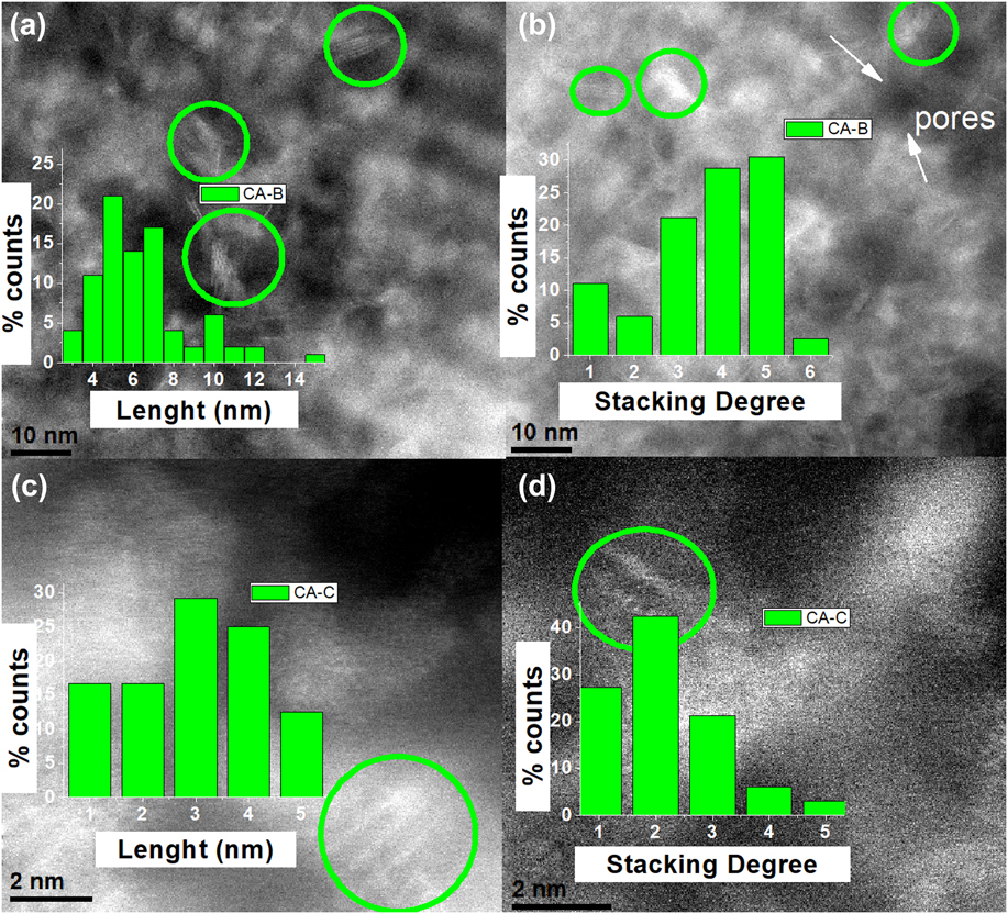
Representatives HR-TEM images of materials synthesized using chelating agents are presented in Fig. 3. In brief, all materials presented the typical morphology of fringes of the MoS2 structure, also the porous structure with a diameter ranging from 7 to 10 nm of the KIT-6, corresponding with the obtained by physisorption analysis. The stacking index and length of the MoS2 crystallites were calculated counting randomly more than 500 particles from different zones of each catalyst. The CA-catalysts and the three-step activation prepared catalysts present average size crystals of 6.4 nm, as shown in Fig. 3(a), and average crystal stacking of 3.7 sulfur slabs [Fig. 3(b)]. The same catalysts synthesized with single step activation show smaller crystals and less stacked, as can be seen in Fig. 3(c) average crystallite length of 3 nm and average stacking of 2.15 sulfur slabs in Fig. 3(d). Therefore, the use of several stages during activation could be allowing greater NiMoS2 crystal growth than when a single activation stage during the preparation of the catalysts was used. It is widely reported that in each stage of thermal treatment, there is a nucleation and growth crystal period that is promoted by the activation in stages.
HRTEM images of catalysts with citric acid as a chelating agent with (a) and (b) methodology B, and (c) and (d) and methodology C.
D. Catalytic hydrodesulphurization activity test
The results of the catalytic HDS evaluation are summarized in Table II. The value of the reaction rate constant was calculated with the L–H (Langmuir–Hinshelwood) equation assuming a pseudo-zero-order reaction. To be able to evaluate the chelating agent effect, a reference material was synthesized according to the methodology A without a chelating agent.
The catalysts synthesized with no calcination and three-step activation have the lowest catalytic performance with a reaction rate constant of 7, 5, 1, and 2.4 × 10⁻⁷ mol/(s g) for CA-A, EDTA-A, PAA-1-A, PAA-9-A, respectively. Meanwhile, when the chelating agent was eliminated before the activation, the reaction rate constant increased significantly up to 12.5 × 10⁻⁷ mol/(s g) for the EDTA-B catalyst and to 9.4, 7, and 6 × 10⁻⁷ mol/(s g) for CA-B, PAA-1-B, and PAA-9-B, respectively. Thus, the increase in molecular weight of the chelating agent reduced the catalytic performance of the materials obtained. In the same way, using a calcination stage had a positive effect on the catalytic activity shown by the materials.
On the other hand, the use of chelating agents by methodology C clearly allows us to overcome the catalytic activity of the materials compared with the reference catalyst rate constant of 8 × 10⁻⁷ mol/(s g). Moreover, the catalyst CA-C showed the best performance in the HDS of DBT shows an activity [18 × 10−7 mol/(s g)] 2.3 times higher than the reference, with 8 × 10⁻⁷ mol/(s g), even when the reference catalyst has better textural properties than the catalyst prepared with chelating agents (480 m2/g, 0.8 cm3/g, and 70 Å, of surface area, pore volume and pore size, respectively).
E. Thermogravimetric analysis
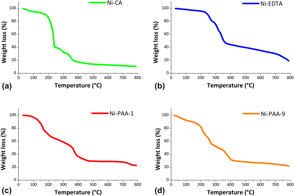
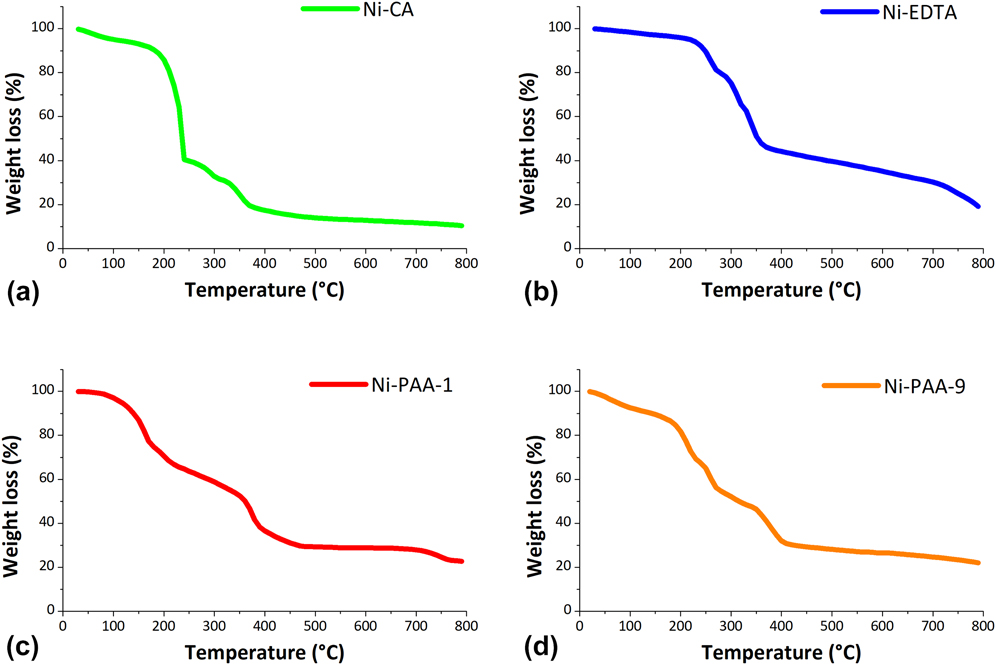
To understand the effect of the chelating agent on the activity of the materials, a TGA analysis was carried out to the complex of the Ni-chelating agent under inert atmosphere (N2). The Ni-chelate complex shows similar weight losses. For all samples, the first weight loss in the plots concerns to the absorbed water on the samples; however, as the temperature increases, the thermal stability of the molecules depends on the chemistry and molecular mass. For citric acid [the smallest molecule; Fig. 4 (a)], the higher weight loss occurs at 250 °C, followed by the nickel nitrate degradation [Fig. 4(b)]. EDTA has a higher molecular weight than the CA and first occurs the elimination of carboxylic acid around of 250 °C, around 300 °C then amine groups are eliminated, finally weight loss at 350 °C approximately the nitrate from nickel precursor was removed. Respect to the polymeric agent [Figs. 4(c) and (d)], a similar behavior same as the EDTA was observed, carboxylic acids are eliminated at beginning, then the main chain from the polymer, finally, the remaining material is a mixture of nickel oxide and carbon, this residue is constant in all of the Ni-complex, except for EDTA that also have sodium from the EDTA salt.
TGA of the complex Ni-chelating agent on nitrogen atmosphere (a) Ni and citric acid complex, (b) Ni and EDTA complex, (c) Ni and PAA-1 complex, (d) Ni and PAA-9 complex.
IV. DISCUSSION
Considering the results obtained in this research work, different mechanisms are proposed. In the first mechanism, the chelating agent is considering as a viscosity modifier; usually, the precursor is added in aqueous solution into the support, and, subsequently, the water is removed with temperature treatment. This leads to the metal precursor displacement and migration of the pores, decreasing the surface area of the mesoporous silica. When a chelating agent is added, an increase of viscosity is observed upon solvent evaporation, which slows down the metal migration; thus, a better-dispersed catalyst is obtained.Reference Vandillen, Terorde, Lensveld, Geus and Debjong4,Reference Al-Dalama and Stanislaus16 Comparing the reaction rate constants of the catalysts with chelating agents and calcination step [k = 9.4, 12.5, 7, 6 × 10⁻⁷ mol/(s g)] to the reference catalyst without chelating agent and no calcination [k = 8 × 10⁻⁷ mol/(s g)], the effect of the viscosity on the better dispersion of the catalyst and consequently higher catalytic activity can be appreciated. The catalysts from polymeric chelating agents have a smaller reaction rate constant, which could be associated with a greater carbon residue after the calcination. The viscosity increase leads to the enhancement of the reaction rate constant from 8 to 9.4 and 12.5 × 10⁻⁷ mol/(s g) for CA-B and EDTA-B, respectively.
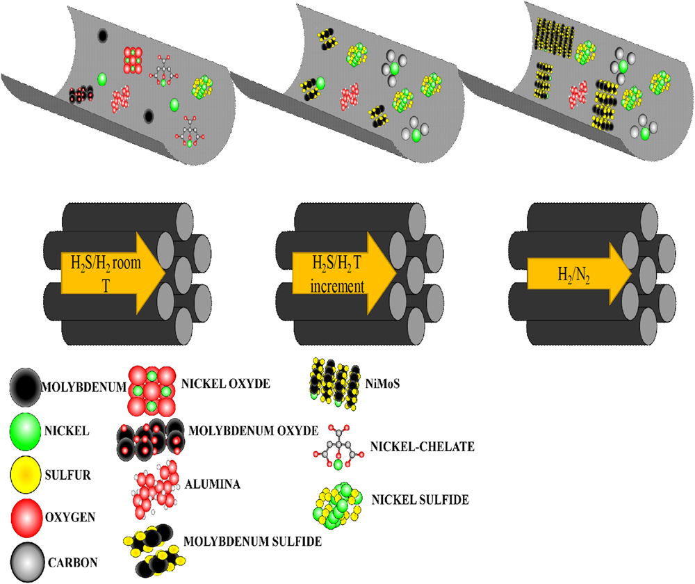
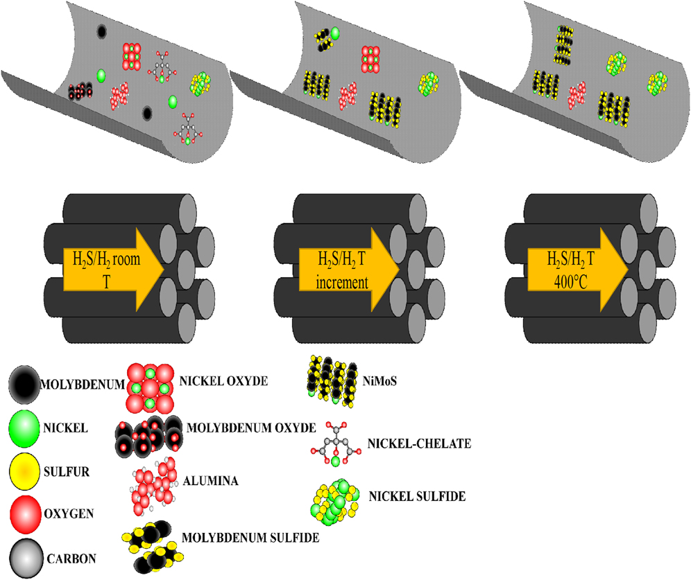
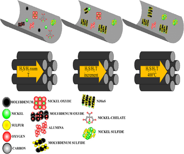
On the other hand, the other two proposed mechanisms (Figs. 5 and 6 to second and third mechanisms, respectively) consider that the chelating agent acts as a nickel trap. Consequently, the order in which sulfidation takes place was changed; thereby, at standard conditions (without chelating agent), nickel sulfidation occurs at room temperature and molybdenum sulfidation occurs between 75 and 225 °C.Reference Coulier7 In the presence of the chelating agent, the order is altered, and nickel sulfidation starts at 250 °C and finishes at 300 °C. After molybdenum sulfidation, this allows a greater NiMoS phase formation and less bulk nickel sulfide. It is widely known that the catalytic activity in HDS is attributed to the NiMoS phase; then, this mechanism allows us to explain the greater constant of reaction speed obtained in the presence of chelating agents.
Mechanism of three-step activation of the catalyst with a chelating agent.

Mechanism of single step activation of the catalyst with a chelating agent.
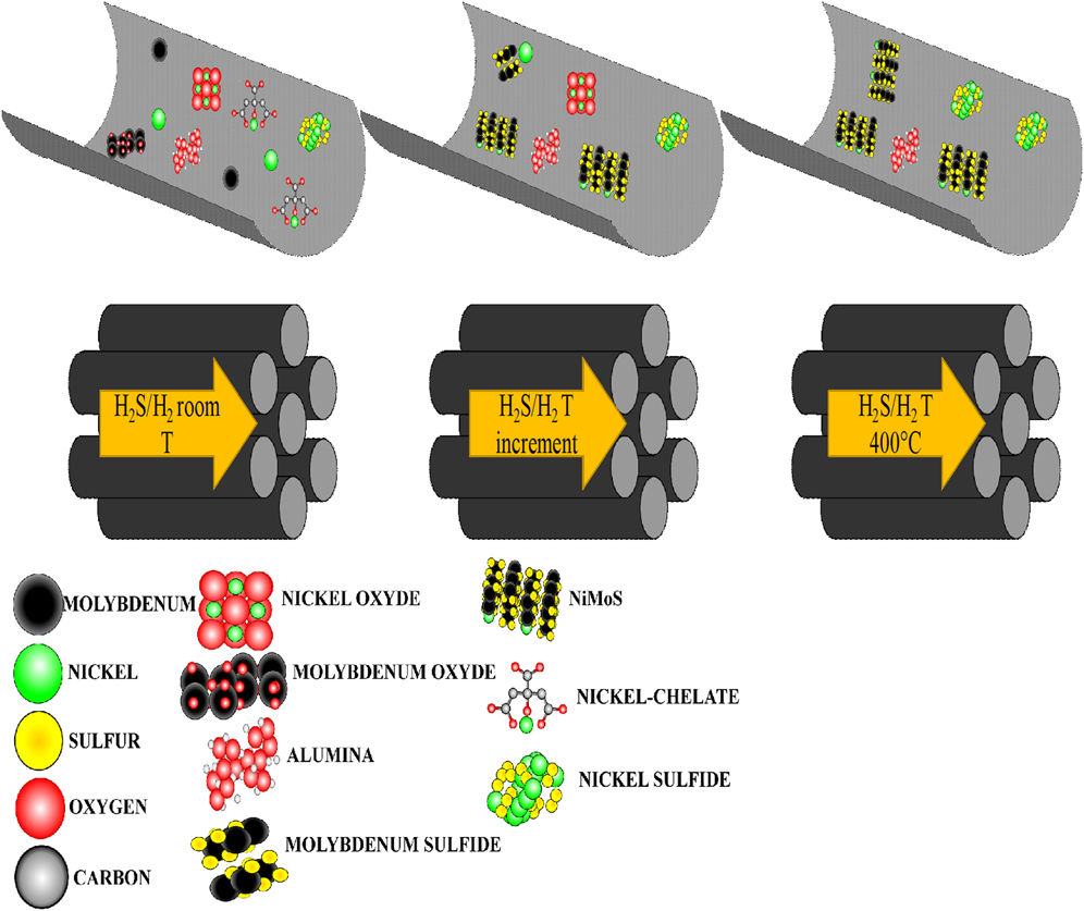
Figure 5 schematizes the mechanism of chelation in a three-step activation. Into the rectangle are represented the different molecules involved in the sulfidation, and the figure represents the support with a magnification of the pores inside, in which are located molecules such as nickel oxide, molybdenum oxide, and nickel–chelate complex. The sulforeductive atmosphere transforms the oxide into monometallic sulfides (nickel sulfide and molybdenum sulfide). At room temperature, the composition inside pores, it is almost oxides and nickel–chelate complex, then an abrupt temperature change occurs (300 °C). This could cause coking in the complex, and when temperature rises at 400 °C, the atmosphere (H2/N2) is no longer suitable to obtain sulfides. This leads to a catalyst with a mixture of MoS2, NiSx phases, and nickel surrounded by carbon, with a low catalytic performance.
The third mechanism (Fig. 6) implicates the single step activation, which has a slow temperature ramp that allows molybdenum start sulfide,Reference Jo, Kim and Ryoo28 and when most of molybdenum form MoS2, then the gradual decomposition of the Ni-Chelate complex begin (start sulfidation at 250 °C and ends at 300 °C)Reference Vogelaar8,Reference Ramírez and Sánchez-Minero29 which permits the liberating of nickel atoms and permitting to decorate the rim and edges of the already formed MoS2 (sulfidation starts at 75 °C and ends at 225 °C),Reference Coulier7,Reference Trejo, Rana and Ancheyta30 obtaining a majority of NiMoS active phasesReference Badoga, Mouli, Soni, Dalai and Adjaye31 and thus a very active catalyst with a rate constant of 18 × 10−7 mol/(s g).
V. CONCLUSIONS
In the present work, a series of NiMo catalysts supported on KIT-6 with 10% atom content of aluminum with three different chelating agents were prepared. The chelating agent (only for CA and EDTA) increases the HDS activity slowing down the displacement of nickel on the support surface during the drying step in the synthesis of the catalyst, allowing thus a better dispersion of the metals over the entire surface. Additionally, the chelating agents improve the sulfidation, changing the order in which they react, first allowing the formation of MoS2 and then releasing the nickel to form the NiMoS phase, which is highly HDS active. According to results on the HDS performance of catalysts prepared by different activation methods and different chelating agents, chelating agents aid to have a highly dispersed active phase for NiMoS-based catalysts prepared by impregnation; however, it is important to design a sulfidation methodology for every cheating agent used.
ACKNOWLEDGMENTS
The authors gratefully acknowledge the Mexican Council of Science and Technology (CONACYT) and to the Energy Department (SENER) for supporting this work through the projects CONACYT-SENER-Hidrocarburos No. 120135. In addition, the authors acknowledge the excellent work of Carlos Elias Ornelas Gutierrez from NanoTech CIMAV for technical support for TEM images.