

Introduction
Autonomous vehicle guidance to perform farming operations such as planting, maintenance and harvesting in cultures such as vegetable, vineyard, horticulture, can be achieved from many kinds of sensors which can locate some crops, either in absolute mode with GPS devices or in relative mode using sensors like LiDAR or camera devices. Research works about automatic guidance for agricultural vehicles were achieved (Keicher and Seufert, Reference Keicher and Seufert2000) and (Ming et al., Reference Ming, Kenji, Katsuhiro and Shinya2008). Robotic technology, with the use of different sensors such as GPS, cameras or lasers to detect and locate weeds could reduce dependency on herbicides, improving sustainability and reducing environmental impact. Various automatic systems have demonstrated the potential of this technology in the field, for various crops. An essential aspect of automatic guidance is the ability to identify the pathway between the crop rows. GPS and machine vision fused together, and also with others technologies, are the trend for agricultural vehicle guidance systems. As most crops are cultivated in rows, an important step towards this long-term goal is the development of a row-recognition system, which allows a robot to accurately follow a row of plants. However, losses of GPS signal, as example if the vehicle penetrates in an environment with many trees, prevent to perform autonomous tasks with accuracy. In many applications, acceleration data given by an Inertial Measurement Unit (IMU) are used, to correct GPS signals, during a short time (Takai et al., Reference Takai, Barawid, Ishii and Noguchi2014). For different crops, like for example citrus groves, the tree canopy frequently could block the satellite signals to the GPS receiver. In this case, perception relative sensors, such as LiDAR or camera devices, embedded on a tractor, can be employed, to detect and follow crop rows (Subramanian et al., Reference Subramanian, Burks and Arroyo2006). Among relative perception sensors, Time of Flight cameras or LiDAR 3D, such as the celebrated Velodyne (Haselick et al., Reference Haselick, Arends, Lang and Paulus2012), could be embedded on vehicles, to get 3D information, in agricultural fields, in order to obtain crop information. However to get information of a set of crops, to realize a crop row tracking operation, a simple LiDAR 2D associated or not with a camera, is sufficient for this task. Both LiDAR sensor and vision systems used separately or in fusion mode, permit to achieve many crop row tracking tasks, for sugar beet (Åstrand and Baerveldt, Reference Åstrand and Baerveldt2002), cotton crops (Billingssley and Schoenfisch, Reference Billingssley and Schoenfisch1995) or rice rows (Choi et al., Reference Choi, Han, Han, Park, Kim and Kim2015). Finding guidance information such as known crop row spacing is a solution for achieving accurate control of the vehicle (Han et al., Reference Han, Zhang, Ni and Reid2003). In the application presented in this paper, a LiDAR device, a IMU sensor and a color camera, were used in a fusion mode, to get the natural object positions, in real time, in a culture. Sensors were embedded on a light mobile robot. Soil perturbations affected the autonomous navigation in cultures. In a first stage, IMU data permitted to correct position of LiDAR points detected in robot environment. Then a fusion method was applied between these corrected points and a color camera, in order to identify and classify each point. Using a color database corresponding to two pixels classes (class crop and others (grass, leaf, soil), identification with the Support Vector Machine (SVM) classic algorithm (Hyeran and Seong-Whan, 2002), permitted to eliminate the noise and to only keep the points which belonged to crops. From these points, one method was applied to get the geometric data of the crop row. Two methods were tested and compared, Hough and Least Square (LS) technique in order to choose the most adapted for crop row tracking tasks. Finally automatic control/command operations were applied to follow crop rows, after setting a lateral distance between the vehicle and the crop row. Fusion applications between a LiDAR and a color camera, was used in various applications, for detecting tree trunks (Shalal et al., Reference Shalal, Low, McCarthy and Hancock2013), or for autonomous vehicle guidance in cultures (Garcia-Alegre et al., Reference Garcia-Alegre, Martin, Garcia-Alegre and Guinea Diaz2011), using tractors. The fusion method improves the recognition of outdoor objects with the combination of the rich and colorful representation provided by images with the planar data given by LiDAR devices. The aim was to develop a system able to track crop rows, with accuracy, working in different fields, in various working conditions: soil perturbations, different speeds, various vegetation levels.
Materials and methods
Mobile robot and sensors
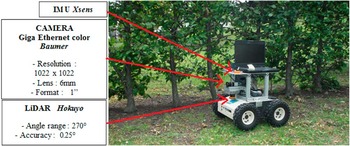
The light mobile robot used in the experimentations is presented in Figure 1. Three sensors were embedded on this vehicle: a GigaEthernet Camera, with a resolution of 1022×1022 pixels (Baumer VLG 40 C), a LiDAR device (Hokuyo UTM-30LX) and an IMU (Xsens).
Mobile robot with color Camera, LiDAR and IMU

Crop row tracking operation principle
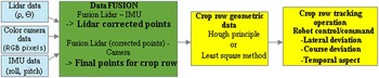
The chart below (Figure 2) shows the various stages carried out to realize the crop row tracking task. First, LiDAR device enabled to obtain 3D points in the environment. These ones were corrected using data given by IMU device. All the geometric points situated outside a desired region, were eliminated. Then a second fusion operation between corrected LiDAR data and color Camera information enabled to get the desired color points, corresponding to objects that must be tracked by robot. For vineyard, the aim was to detect trunk points and to eliminate the green ones corresponding to grass and leaf. One method like LS technique or Hough method was then applied to obtain at the end, the line geometric information used for crop row tracking operation. Finally, the robot control algorithm was launched, using the line information, the desired lateral deviation and taking into account also the robot angular deviation, the temporal aspect, and the variable spacing between natural objects in crop rows.
Crop row tracking operation

Fusion LiDAR/IMU
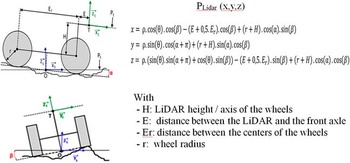
LiDAR device enabled to obtain 3D points in the environment. These ones were corrected using pitch and roll angular data given by IMU device. Figure 3 presents the robot model, with different geometric parameters in order to compute the point coordinates PLidar(x,y,z), taking into account LiDAR and IMU data, respectively (ρ, ϴ) and (roll (α), pitch (β)). Points outside the desired search place, particularly points situated under a height limit (corresponding to grass height eg 0.1 m) were eliminated.
Robot model – Fusion LiDAR/IMU

Fusion Camera/LiDAR
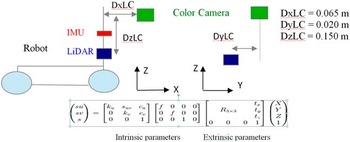
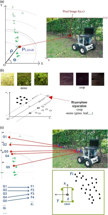
The Camera calibration and the information about relative position of both sensors embedded on robot, permitted to get intrinsic and extrinsic parameters of the LiDAR-Camera system, in order to realize the fusion between both sensors (Figure 4).
Calibration Camera/LiDAR

For each corrected LiDAR point PLidar , put by fusion on image (Figure 5, a), a window (10×10 pixels) was considered around each one, in order to identify each point, taking into account the color of all pixels inside the window. Two pixel classes were considered: crop (trunk, branch) and noise (leaf, grass, soil,…). (Figure 5, b) presents some color samples for both selected color classes for the application. A SVM method was used to achieve this color discrimination (hyperplane to separate both classes), in order to classify and identify pixels on images, detected with LiDAR device, during vehicle navigation. For each PLidar point (called Gi in Figure 5, c), if the pixel number inside the window which belonged to crop class was superior to a desired threshold (fixed to 20), then the PLidar point Gi was kept (final point Fj), for obtaining, in the next stage, the geometric parameters of the crop line. Otherwise, PLidar point was eliminated.
Fusion Camera/LiDAR

Crop row detection method
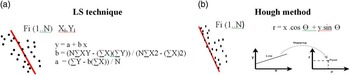
Two methods were tested to obtain, from the final points (Fi) obtained by fusion methods, the crop row geometric information used for tracking operation (Figure 6): the LS technique with the crop line computation presented in (a) and the Hough method (Duda and Hart, Reference Duda and Hart1972) (b). Hough method consisted of working in (r,Ɵ) space in which a point characterizes a line, and to increment a matrix accumulator, considering all points Fi, and with variations of both variables r [rmin;rmax] and Ɵ [Ɵmin;Ɵmax]. The maximum value of the matrix corresponded to the desired crop line.
Crop row detection

Robot control for crop row tracking
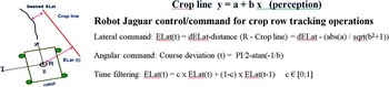
The robot control algorithm was launched, using the line information (y=a+bx), the desired lateral deviation (dELat) and taking into account also the robot angular deviation and the temporal aspect (Figure 7), in order to avoid high robot movements during navigation.
Robot control for crop row tracking

Results
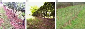
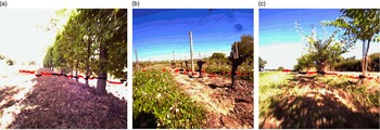
Experimentations were achieved in three different crops (Figure 8), particularly vineyard environment, in order to study the capability of the developed fusion method, to realize crop row tracking operations, with accuracy, working with various robot speeds between 1 and 3 m s−1, various vegetation levels and ground perturbations such as holes, bumps or mud.
Test fields for crop row tracking operations

Fusion method to detect crop points
Figure 9 presents results images with LiDAR points put on images, in order to discriminate color pixels (crop and no crop). Black and red color points are, respectively, the crop points that are tracked by vehicle and noise points corresponding to either points which have not crop color or points outside the desired place where the user is looking for tracking points.
Fusion results

A lot of noise points corresponding to soil, grass or leaf were detected by LiDAR device. The colorimetric discrimination enabled to eliminate these objects, to keep only, finally, crop elements (set of points characterized by geometric position in 3D environment).
Comparison between LS technique and Hough method for navigation
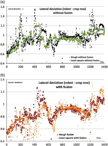
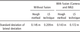
A study was carried out to compare two methods to get, from crop points, the crop line geometric parameters which must be tracked by vehicle. The standard deviation differences, between both methods, in lateral deviation values, presented in Figure 10 and Table 1 (manual navigations, working without (a) or with (b) fusion mode with camera, near a crop line), showed that Hough method was less sensitive to noise, gave more stable information and permitted to get less oscillation, in the robot navigation than LS technique.
Experimental data for comparison between LS technique and Hough method

Statistical data for comparison between LS technique and Hough method

Hough method with fusion (LiDAR, IMU and Camera) was the most stable, to detect and follow crop rows, particularly in a noise environment. Anyway, Hough method is much slower (processing time) than LS technique so for high speed applications, with a few noise points detected by LiDAR device in crop environment, it could be better to use this last one.
Autonomous navigation results
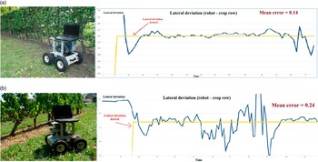
Figure 11 present crop row autonomous tracking result examples, without (a) and with (b) soil perturbations (vines). In these tests, Hough method was carried out, the fusion with IMU and Camera was used, the control/command speed was 1 m s-1 and the navigation distance was 50 m. The c coefficient for temporal filtering was 0.8. The desired lateral deviation value (dELat) was 1.5 m.
-
For all tests carried out, the mean error for lateral deviation between robot and crop row, varied in the rang [0.1-0.2 m] and [0.2-0.3 m] respectively for soil without and with perturbations such as vines. Figure 12 presents crop row autonomous tracking result examples, without (a) and with (b) soil perturbations (vines), working with a speed of 1.5 m/s. As example, the difference between mean absolute error for two robot speeds 1 m s−1 and 1.5 m s−1, was about 0.06 m and 0.11 m, respectively for tests without and with soil perturbations, working in the same crops, modifying only speed value. For many tests, mean error for lateral deviation was about 0.25 m and 0.4 m, respectively for soils without and with perturbations.
Crop row tracking on soil without and with perturbations

Speed influence on crop row tracking accuracy

Conclusions
The results obtained working with a light mobile robot in different navigation conditions, in various crops, showed the robustness of developed fusion method, for realizing stable autonomous navigation for crop row tracking, particularly in the vineyards, with many perturbation and speeds up to 2 m s−1. Hough method enabled to obtain a better ground truth at less oscillation in navigation than LS technique because it permits to detect the exterior points of trees. The mean lateral error between desired and obtained trajectory varied between 0.1 and 0.4 m, depending of speed and soil perturbations. Over than 2 m s−1, the robot could not navigate with stability, particularly in vineyards environment.
This developed system, with three aspects (perception/fusion/control) will be carried on heavier vehicles or other mobile robot less sensitive to soil perturbations, to be able to work with high speeds over than 2 m s−1. In parallel to these crop row tracking works, a study was carried out about the robot traversability in crop rows, which consisted, in a first stage to detect and locate some obstacles in front of vehicle (grass, leaf, branches in front of vehicles) during navigation, and in a second stage, to avoid or cross these ones, at reduced speed, taking into account their physical characteristics (object type, size). Traversability works will be applied in crop row tracking tasks to complete and optimize these operations, using a light robot or a tractor.