
1. Introduction
The deformation and breakup of droplets accelerated by a shock wave is a typical phenomenon of a high-speed interfacial flow, which plays an important role in aerospace and national defense industries, such as evaluation of raindrop damage on supersonic aircraft, spray combustion in internal combustion engines and rocket engines, and high-speed delivery of bulk chemical weapons (Eggers & Villermaux Reference Eggers and Villermaux2008; Villermaux & Bossa Reference Villermaux and Bossa2009; Lefebvre & McDonell Reference Lefebvre and McDonell2017). In these applications the droplets usually attach onto the solid wall due to the hydrodynamic impact and adhesion, and the wall effect on the high-speed flow makes the aerobreakup dynamics of wall-attached droplets much more complex than the free spherical droplets (Baumgarten Reference Baumgarten2006; Shen et al. Reference Shen, Li, Liu, Si, Liu, Tang and Fan2019). Therefore, it is of great application value to study the shock induced aerobreakup of liquid droplets attached on the wall.
The aerobreakup of a free spherical droplet in an air stream has been widely studied for decades (Simpkins & Bales Reference Simpkins and Bales1972; Gelfand Reference Gelfand1996). The pioneering work of Hinze (Reference Hinze1955) has pointed out that the Weber number is the essential parameter that determines the droplet aerobreakup dynamics. He also studied the effect of droplet viscosity on aerobreakup, and found that the droplet viscosity will inhibit the rate of droplet deformation. Further studies carried out by other researchers have found more abundant fragmentation modes of droplet aerobreakup. A widely recognized way to divide the droplet aerobreakup modes has been proposed (Pilch & Erdman Reference Pilch and Erdman1987; Guildenbecher, López-Rivera & Sojka Reference Guildenbecher, López-Rivera and Sojka2009), where the aerobreakup modes are divided into five different categories as the Weber number of the droplet gradually increases, i.e. the bag breakup, the bag and stamen breakup, the sheet thinning breakup, the wave crest stripping breakup and the catastrophic breakup. The Ohnesorge number was found to affect the critical Weber number between different aerobreakup modes. However, there still remains conflicts on the existence of the catastrophic breakup mode. With the development of experimental technology, more details on the evolution dynamics of a liquid droplet can be obtained. Theofanous (Reference Theofanous2011) reclassified the droplet breakup modes into two types. At a low Weber number, the deformation of the droplet is dominated by the Rayleigh–Taylor (R–T) instability, thus, the aerobreakup of the droplet is defined as the Rayleigh–Taylor piercing (RTP) mode. At a high Weber number, as the surrounding high-speed airflow brings in a strong shear effect and Kelvin–Helmholtz (K–H) instability on the droplet surface, the peeling off of liquid mist occurs at the equatorial edge of the droplet. This kind of droplet breakup corresponds to the shear-induced entrainment (SIE) mode.
For the case of the RTP mode that occurs at a low Weber number, the droplet is compressed in the airflow due to the pressure difference between the windward and leeward side. After the droplet flattens into the disk profile, the centre of the droplet expands backward to form a bag-like structure due to the high pressure at the stagnation point on the windward side. As the bag increases, it will eventually break into a large number of child droplets. When increasing the Weber number of the droplets, the droplets will undergo bag and stamen breakup, in which a liquid column protrusion occurs in the middle of the bag (Pilch & Erdman Reference Pilch and Erdman1987; Wierzba Reference Wierzba1990; Guildenbecher et al. Reference Guildenbecher, López-Rivera and Sojka2009). The physical mechanisms of droplet aerobreakup in the RTP mode has been studied in detail. Two typical dynamic models to describe the droplet breakup are proposed, including the Taylor analogy break (TAB) model (O'Rourke & Amsden Reference O'Rourke and Amsden1987) and the drop deformation breakup (DDB) model (Ibrahim, Yang & Przekwas Reference Ibrahim, Yang and Przekwas1993). The TAB model approximates the droplet as a damped elastic system that vibrates under the external aerodynamic force, the average diameter of sub-droplets after breakup can be obtained by using the conservation of energy. The DDB model assumes that the rate of change of the total energy of the system equals the sum of the power of the aerodynamic force and the viscous force in the droplet deformation process, which is able to predict the deformation shape of the droplet at the moment of breaking under different Weber numbers. Jackiw & Ashgriz (Reference Jackiw and Ashgriz2021) further provided a mathematical description of the aerobreakup process, which is able to predict the droplet breakup morphology and the size of the child droplets after breakup. Kulkarni & Sojka (Reference Kulkarni and Sojka2014) theoretically deduced the deformation rate on the transverse width of the bag and the thickness of the flattened droplets. Zhao et al. (Reference Zhao, Liu, Li and Xu2010) proposed the R–T wavenumber to predict the droplet breakup mode, and found that the wavenumber increases with the increase of Weber number. The critical wavenumber predicted by theory agreed well with the experimental results.
For the case of SIE mode that occurs at a high Weber number, the shear stress plays a more significant role on droplet breakup. As the droplet gradually flattens, the surface wave appears close to the droplet equators due to the effect of the surrounding airflow. Child droplets are peeled off continuously near the droplet equators, which finally lead to the formation of liquid mist. The occurrence of droplet stripping is attributed to the development of K–H instability that is caused by the velocity difference across the interface (Theofanous & Li Reference Theofanous and Li2008; Guildenbecher et al. Reference Guildenbecher, López-Rivera and Sojka2009). The model based on the R–T and K–H instability theory (RT–KH model) is developed to describe the droplet dynamics in the SIE mode (Reitz Reference Reitz1987). The RT–KH model considers the perturbation growth on the surface of the droplet, and indicates that the diameter of the child droplets is proportional to the most unstable wavelength of K–H instability. Interface morphologies of droplet aerobreakup in the SIE mode are also studied by researchers. Harper, Grube & Chang (Reference Harper, Grube and Chang1972) analysed the growth of the R–T instability that is induced by acceleration on the surface of the liquid droplet. Based on the shadowgraphy method, Joseph, Belanger & Beavers (Reference Joseph, Belanger and Beavers1999); Joseph, Beavers & Funada (Reference Joseph, Beavers and Funada2002) took a series of breakup images with high resolution and measured the wavelength of the R–T instability at the droplet windward surface. The experimental results were found to agree well with the theoretical prediction of the RT–KH model. Recently, full three-dimensional numerical simulations were carried out to reveal the physical mechanism of droplet aerobreakup in the SIE mode. Meng & Colonius (Reference Meng and Colonius2018) extracted the dominate mode of circumferential R–T instability through Fourier decomposition on the azimuthal perturbations. Dorschner et al. (Reference Dorschner, Biasiori-Poulanges, Schmidmayer, El-Rabii and Colonius2020) pointed out that the time of primary breakup is related to the Weber number but the time interval between the secondary and third breakups is independent of the Weber number. Nykteri & Gavaises (Reference Nykteri and Gavaises2021) showed that the symmetrical recirculation zone near the droplet equator is the main reason for the flattening of the droplet profile in the early stage of deformation. The vorticity field and pressure field of the droplet explained the appearance and evolution of surface structure, demonstrating that pressure is the primary inducement for the formation of droplet protrusion (Meng & Colonius Reference Meng and Colonius2015).
The aerodynamic deformation and aerobreakup of droplets under a non-uniform flow field always exist in real situations, which get more attentions by researchers in recent years. Theofanous et al. (Reference Theofanous, Li, Dinh and Chang2007) considered the coupling breakup of two tandem droplets, in which the rear droplet deforms in the wake stream of the front droplet. They also studied the droplet breakup in a non-uniform flow that is produced by the obstacles in front of the droplet, the existence of the obstacle changed the breakup morphology and the critical Weber number of the droplet aerobreakup. Furthermore, Wang et al. (Reference Wang, Hopfes, Giglmaier and Adams2021) experimentally investigated the droplets breakup with a tandem arrangement over a wide range of Weber numbers and droplets distances. A phase diagram was plotted to identify the breakup pattern. Xu, Wang & Che (Reference Xu, Wang and Che2020) utilized the shear layer of the air jet to investigate the influence of a strong shear on droplet breakup and divided different regimes in the regime map of droplet breakup. Soni et al. (Reference Soni, Kirar, Kolhe and Sahu2020) conducted an experimental investigation on the deformation and breakup of droplets in an oblique continuous airflow. The results indicated that the transition from cross-flow to oblique flow leads to a significant decrease of the critical Weber number for bag breakup. Kirar et al. (Reference Kirar, Soni, Kolhe and Sahu2022) studied the droplet deformation in swirl flow experimentally. They found that the swirl flow could promote the development of R–T instability and enhance the stretching process during droplet deformation. The aerobreakup of droplets is directly related to the atomization efficiency in real applications, and the droplet size distribution (DSD) has been studied by researchers in recent years. Jackiw & Ashgriz (Reference Jackiw and Ashgriz2022) considered three different droplet breakup mechanisms and gave a reasonable prediction of the DSD after droplet breakup. More recently, the in-line holography technique has been employed to analyse the DSD, either in the cross-flow (Ade, Chandrala & Sahu Reference Ade, Chandrala and Sahu2023a) or in the swirl air stream (Ade et al. Reference Ade, Kirar, Chandrala and Sahu2023b). An analytical model was also developed, which predicted the experimental results under different Weber numbers.
Aerobreakup of wall-attached droplets is another typical kind of non-uniform flow as the velocity boundary layer exists close to the solid wall. Previous researches on the aerodynamic evolution of wall-attached droplets mainly focused on the low Weber number situation, in which the droplet deforms and migrates without break up (Schmucker, Osterhout & White Reference Schmucker, Osterhout and White2012; Hooshanginejad & Lee Reference Hooshanginejad and Lee2017). The effects of wall temperature, roughness and gravity on the deformation of wall-attached droplets were also studied in detail (Roisman et al. Reference Roisman, Criscione, Tropea, Mandal and Amirfazli2015; White & Schmucker Reference White and Schmucker2021; Hooshanginejad & Lee Reference Hooshanginejad and Lee2022). Up to now, a systematical study on the deformation and breakup of a wall-attached droplet under a high-speed airflow with a large droplet Weber number is still missing. For a high-speed air stream, the velocity boundary layer would exist close to the solid wall, and the effect of the boundary layer on the droplet evolution remains to be studied. Moreover, a clear presentation of the three-dimensional morphology in the whole process of droplet evolution is desired. All these limitations motivate our work.
In this work we depict the dynamic process of a wall-attached liquid droplet under a high-speed air stream. The air stream is generated by an initial shock wave with a certain Mach number 1.2. Droplets with different wettabilities on a solid wall (hydrophobic, hemispherical and hydrophilic) are studied by high-speed imaging captured from three different perspectives. Through the qualitative and quantitative comparison of the breakup process of the spherical droplet and the wall-attached droplets, the effect of the wall on the breakup of the droplet is investigated. The mechanism on the formation of the special structure of wall-attached droplets is studied. The effect of the solid wall on the perturbation growth of R–T and K–H instabilities is also discussed. This paper is organized as follows. Section 2 shows the experimental set-up, including the droplet generation method, the layout of experiment devices and initial conditions of the experiments. Section 3 shows the details of shock wave-droplet interaction dynamics and the morphology of the aerobreakup of the wall-attached droplet from multiple perspectives. Section 4 gives the evolution process and the physical mechanism of special structures on the surface of the wall-attached droplet. The analysis of R–T and K–H surface instabilities is shown in § 5. The conclusions of the study are provided in § 6.
2. Experimental methods
Our experiments consider the deformation and breakup of water droplets in an air environment. The density and dynamical viscosity of the water droplets are  $\rho _l=997\,{\rm kg}\,{\rm m}^{-3}$ and
 $\mu _l=0.001\,{\rm Pa}\,{\rm s}$, and the density and dynamical viscosity of the air behind the shock wave are
 $\rho _g=1.59\,{\rm kg}\,{\rm m}^{-3}$ and
 $\mu _g=0.000018\,{\rm Pa}\,{\rm s}$, respectively. The water–air surface tension is
 $\sigma _l=72\, {\rm mN}\,{\rm m}^{-1}$. The key point of the experiment is to generate the wall-attached droplets with controllable contact angle
 $\theta$, as shown in figure 1(a). The wettability of the solid wall can be modified by coating a thin film with different materials on the wall surface. For example, we utilize the Glaco reagents to realize the hydrophilic surface with
 $\theta >90^{\circ }$. The value of
 $\theta$ can be adjusted through changing the concentration of the Glaco reagents. Similarly, the LSJN728-1 reagents with different concentrations are used to realize the hydrophobic surface with
 $\theta <90^{\circ }$. The hemispherical droplet is realized through pasting a Teflon tape on the test platform. In order to compare the evolutions of wall-attached droplets with the full spherical droplet, we also generate the full spherical droplet in an air environment. For the convenience of analysis, we fix the wall-attached droplets with different wettabilities at a certain equivalent radius of
 $R_0=1.335\, {\rm mm}$, as shown in figure 1(a). It is notable that the real volume
 $V$ and height
 $H$ of the droplet would decrease with the decrease of contact angle, as shown by the sub-graphs (iv), (v) and (vi) in figure 1(a). For the wall-attached droplets with certain contact angle
 $\theta$ and equivalent radius
 $R_0$, geometrical analysis can be used to calculate the height
 $H$ of a droplet, which is
 \begin{equation} H=R_0\left( 1-\cos \theta \right). \end{equation}
(a) Initial condition of wall-attached water droplets, where  $\theta$ denotes the contact angle between the droplet and solid wall,
 $R_0$ denotes the radius of the equivalent spherical droplet and
 $H$ refers to the height of the wall-attached droplet. The sub-graphs (i), (ii) and (iii) show the sketches of the wall-attached droplets with different wettabilities, and (iv), (v) and (vi) show the initial states in experiments. (b) Experimental measurements and theoretical predictions of (2.1) on the height of wall-attached droplets under different contact angles.

Figure 1(b) gives the comparison on the height of wall-attached droplets between (2.1) and the experimental results, showing a good agreement between them. Moreover, as the height of droplets is much smaller than the capillary length ( ${\approx }2.7\,{\rm mm}$ for water), the gravity effect can be ignored in our study.
In order to generate a stable planar shock wave with a certain Mach number, a shock tube facility with open ending is utilized in our experiments. The experimental arrangement of the shock tube facility is shown in figure 2(a). The shock tube is constituted by four main parts, including the driver section (with a certain length of 1.9 m), the driven section (with a certain length of 1.0 m), the transform section (with a certain length of 1.0 m) and the test section (with a certain length of 0.4 m). The open-ending configuration of the shock tube is able to avoid the second impact of the reflected shock wave on the droplet. For the test section, observation windows with transparent glasses are installed on all sides to ensure the observation of experimental results from multiple perspectives. The operating condition of the shock tube is given by the X-T diagram, as shown in figure 2(b), in which IS represents the incident shock wave, RW represents the rarefaction wave, RRW represents the reflected rarefaction wave,  $X_0$ represents the position where the droplets are placed and
 $\Delta T$ represents the effective test time before the reflected rarefaction wave reaches the droplet. By calculating the time difference of wave propagation, the maximal duration of time for experiments is about
 $\Delta T=14$ ms, which is much longer than the droplet deformation time (
 $\sim$1 ms). Figure 2(c) shows the sketch of the test platform where the droplet is placed. The platform is connected to a supporting beam at the tube exit, and the droplet is settled some distance away from the leading edge of the platform. The evolution of the droplet is visualized from three different perspectives: the side view, the oblique front view and the back view. The shock wave and the post-wave air stream flow along the
 $Y$ direction, the direction perpendicular to the wall is the
 $Z$ direction, and the direction from the side view is the
 $X$ direction. The whole process of our experiment is introduced as follows. Firstly, a plastic diaphragm is placed between the driver and driven sections, and the water droplet is formed on the surface of the platform in the test section. A pipette gun is used to control the droplet with a precise volume. Then, the air is injected into the driver section continuously through an air compressor. As the pressure difference between the driver and driven section exceeds the critical value to maintain a complete diaphragm, the diaphragm bursts suddenly with the formation of an incident shock wave. The incident shock wave and the post-wave air stream propagate downstream and interact with the droplet. The evolutions of the shock wave and the wall-attached droplets are captured at the test section.
Experimental arrangement of the shock tube facility. (a) Sketch of the shock tube system. (b) The X-T diagram on the propagation of waves inside the shock tube, where IS denotes the incident shock wave, RW denotes the rarefaction wave, RRW denotes the reflected rarefaction wave at the opening end,  $X_0$ denotes the position where the droplets are placed and
 $\Delta T$ measures the effective time of duration in experiments. (c) Sketch of the platform for flow visualization from different directions.

In our experiments two typical methods were used to capture the dynamics of the shock wave and droplet aerobreakup, i.e. high-speed schlieren and high-speed photography. The high-speed schlieren method is able to capture the propagation of the shock wave and the interaction between the shock wave and the wall-attached droplet. A detailed introduction of the schlieren method and typical experimental results are given in § 3.1. The high-speed photography method is used to depict the deformation and breakup process of droplets, such as the growth of perturbation on the interface of droplets. In high-speed photography the frame rate of the camera (Phantom V2012) is set to  $10^5$ fps. The light source (SLG-150 V) is illuminated from the top of the droplet (
 $Z$ direction). It is notable that in previous studies the droplet deformation and breakup are usually recorded under a backlight light path (Luc & Hazem Reference Luc and Hazem2019; Poplavski et al. Reference Poplavski, Minakov, Shebeleva and Boyko2020). The backlight arrangement can capture the droplet profile clearly, which enables the investigation on droplet movement and the quantitative measurement of the R–T and K–H perturbation waves. However, it fails to show the fine structures on the droplet surface due to the light scattering across the droplets. Laser-induced fluorescence (LIF) was utilized to capture the details on the droplet windward and backward surfaces, which confirmed the piercing of R–T waves on the droplet and also captured the groove structure on the droplet surface (Theofanous & Li Reference Theofanous and Li2008; Theofanous et al. Reference Theofanous, Mitkin, Ng, Chang, Deng and Sushchikh2012). The LIF results from the oblique front direction revealed the growth circumferential wave on the windward side. For the top illumination arrangement in our experiment, the diffuse reflection of light from the platform is able to light the whole droplet surface. Therefore, the microstructures on the droplet surface can be captured clearly, leading to a similar effect to the results obtained from LIF.
In the aerodynamics of droplet deformation, the inertial force, viscous force and surface tension force are the main factors that influence the evolution characteristics of the liquid droplet. The Reynolds number ( $Re$) and Weber number (
 $We$) are defined to measure the relative importance between these forces, i.e.
 \begin{equation} \left. \begin{aligned} & Re=\frac{\rho _gU_gD_0}{\mu _g},\\ & We=\frac{\rho _gU_{g}^{2}D_0}{\sigma _l}, \end{aligned} \right\} \end{equation}
where  $D_0$ (=2
 $R_0$) refers to the equivalent diameter of the droplet and
 $U_g$ is the flow velocity of the post-wave air stream. A one-dimensional gas dynamics equation can be used to determine the value of
 $U_g$, which is
 \begin{equation} U_g=\frac{2\gamma _1}{\gamma _1+1}\left( M_s-\frac{1}{M_s} \right), \end{equation}
where  $\gamma _1$ is the gas adiabatic coefficient and
 $M_s$ denotes the shock wave Mach number. The adiabatic coefficient of air is
 $\gamma _1=1.4$, and
 $M_s$ can be calculated through high-speed schlieren. It can be clearly seen that an increase of
 $M_s$ can increase the Weber number and the Reynolds number of droplet evolution. Previous studies (Schmucker et al. Reference Schmucker, Osterhout and White2012; Hooshanginejad & Lee Reference Hooshanginejad and Lee2017) have indicated that if the value of
 $We$ is relatively small (e.g.
 $We\sim O(10)$ or less, corresponding to
 $M_s < 1.05$), the aerodynamic force is unable to overcome the surface tension of the wall-attached droplet. Therefore, the droplets would undergo migration and deformation without interface breakup. The increase of
 $We$ gradually leads to the aerobreakup and atomization of wall-attached droplets. As the value of
 $We$ ranges in the order of
 $10^2 \sim 10^3$, the aerobreakup mode of the droplet would be located between the RTP and SIE modes (Guildenbecher et al. Reference Guildenbecher, López-Rivera and Sojka2009; Theofanous Reference Theofanous2011), indicating that both the R–T instability and K–H instability play a significant role on droplet deformation and breakup. As the Weber number further increases to relatively large values (e.g.
 $We\sim O(10^4)$ or more), the K–H instability dominates the droplet aerobreakup, and the droplets atomize to sub-droplets very fast due to the strong shear effect of the airflow. In this work the value of
 $M_s$ is selected as 1.2. According to (2.3),
 $U_g=103.88\,\textrm {m}\,\textrm {s}^{-1}$ can be obtained, and the Weber number and the Reynolds number can be calculated to be
 $We=641$ and
 $Re=25\,053$, respectively. In this situation, the evolution of droplets is dominated by the R–T and K–H instabilities jointly, and the viscous force only plays a negligible role at
 $Re \sim 10^5$. We choose the equivalent droplet diameter
 $D_0$ as the characteristic length. The characteristic time is chosen as
 $({U_g}/{D_0})\sqrt {{\rho _g}/{\rho _l}}$, which is the same with the situations of a spherical droplet considered previously (Theofanous Reference Theofanous2011; Meng & Colonius Reference Meng and Colonius2018). Therefore, the evolutions of wall-attached droplets with different wettabilities have the same characteristic time. The dimensionless time
 $t^*$ can be calculated by
 \begin{equation} t^*=t \boldsymbol{\cdot} \frac{U_g}{D_0}\sqrt{\frac{\rho _g}{\rho _l}}, \end{equation}
where  $t$ is the dimensional time.
Table 1 summarizes the initial geometrical and flow parameters of different cases in our experiments. We mainly consider the wall-attached droplets with five different contact angles. The results are also compared with the spherical droplet case quantitatively under a similar value of Weber number.
Parameters corresponding to the initial conditions for different cases, where  $\theta$ denotes the degree of contact angle,
 $V$ denotes the volume of the droplet,
 $H$ denotes the height of the droplet and
 $W$ denotes the lateral width of the droplet.

3. Aerobreakup process of wall-attached droplets
3.1. Shock wave-droplet interaction dynamics
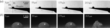
In the aerobreakup process of a wall-attached droplet induced by a shock wave, the droplet first interacts with the shock wave and then deforms and breaks up in the post-wave air stream. The results obtained from the high-speed schlieren method are shown in figure 3(a), in which the evolution of a hemispherical droplet at different dimensional time is considered. In the experiments the zero time instant ( $t=0\,\mathrm {\mu }\textrm {s}$) is chosen at the moment when the shock wave contacts the front edge of the droplet. The Mach number of the shock wave can be calculated according to the displacement distance of the shock wave in two adjacent images, which is
 $M_s=1.2$ in figure 3(a). It can be seen that after the incident shock wave impacts the wall-attached droplet, the reflected shock wave appears from the windward side of the droplet (see the sub-graph
 $t=3\, \mathrm {\mu }\textrm {s}$). After the shock passes through the droplet (
 $t=53\, \mathrm {\mu }\textrm {s}$), the overall shape of the droplet does not change immediately, suggesting that the impacting and diffraction of the shock wave on the droplet only have a negligible effect on the deformation of the droplet. Due to the high acoustic impedance of the liquid, the transmitted shock wave that enters inside the droplet is very weak compared with the initial shock wave, thus, it also plays an insignificant role on the deformation of droplet, especially at low Mach number (Meng & Colonius Reference Meng and Colonius2018). The constant high-speed airflow behind the shock wave gradually leads to the deformation and breakup of the wall-attached droplet (see the sub-graphs at
 $t=173\, \mathrm {\mu }\textrm {s}$ and
 $213\, \mathrm {\mu }\textrm {s}$). As the droplet
 $We$ is relatively high (
 $We=641$), the shear effect of airflow can stretch the interface to the ligament, which finally disintegrates to liquid mist. Figure 3(b) shows the droplet morphologies captured through high-speed photography. It is notable that the droplet shows almost no deformation when the shock wave passes by. Therefore, we mainly focus on the droplet evolution in the post-wave air stream in the later stage. As the results obtained from the schlieren method can not offer more details of interface perturbations on the droplet, we use the high-speed photography method to capture the interface evolution during droplet breakup.
Comparison of high-speed schlieren and photography results at the same time. (a) Aerobreakup process of hemispherical droplet captured by high-speed schlieren, in which IS denotes the incident shock wave and RS denotes the reflected shock wave. (b) Aerobreakup process of hemispherical droplet captured by high-speed photography.

3.2. Morphology of wall-attached droplets
The morphologies of the droplet during the deformation and aerobreakup process in the post-wave air stream are studied in this section. In order to obtain the fine structures and perturbation growth on the droplet surface we capture the droplet evolution from three perspectives by high-speed photography. The situations of wall-attached droplets with different wettabilities are shown in figures 4–6. The results will be further compared with the case of a spherical droplet, under the same values of dimensionless parameters (see figures 7 and 8).
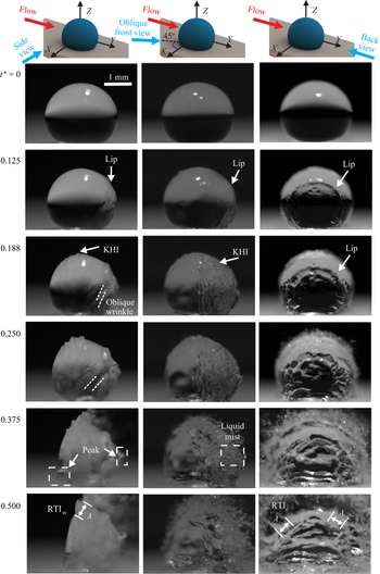
Figure 4 shows the deformation process of a hydrophobic droplet from three perspectives, in which the left, the middle and the right columns denote the pictures taken from the side view, the oblique front view and the back view, respectively. The evolution of the droplet on each side is also given in supplementary movie 1 available at https://doi.org/10.1017/jfm.2023.612. For the convenience of analysis, we non-dimensionlized the time and reselect the dimensionless zero time instant as the moment when the droplet undergoes visible deformation. With the advancing of dimensionless time ( $t^*=0.125$), obvious perturbation on the droplet surface can be observed, especially at the leeward side of the droplet. Specifically, the annular ‘lip’ structure appears on the leeward side, which can be seen clearly from the back view. It is notable that the ‘lip’ structure also occurs for a free spherical droplet (Luc & Hazem Reference Luc and Hazem2019). However, it is the first time that the ‘lip’ structure can be observed from the back view. The results obtained from the back view enable us to study the morphological evolution of the ‘lip’ and also the circumferential instability of the droplet. A quantitative analysis on the ‘lip’ structure will be carried out in § 4 in detail. At
 $t^*=0.188$, perturbation waves that are caused by the K–H instability appear close to the droplet equator. The K–H instability is caused by a tangential velocity difference on both sides of the gas–liquid surface. The velocity difference leads to a strong shear force on the surface. On the leeward side of the droplet, obvious wrinkles also begin to appear. At
 $t^*=0.25$, the K–H instability and the leeward wrinkles keep growing. Due to the effect of the solid wall, the overall structures of the wrinkles are oblique. The wrinkle development of the wall-attached droplet is totally different from that of a spherical droplet, where the wrinkle structures invariably maintain a vertical position. At
 $t^*=0.375$, liquid mist occurs at the droplet equator with child droplets separating from the main droplet, due to the continuous growth of the K–H instability. From the back view, the circumferential perturbation waves keep growing. Different from the breakup of a spherical droplet where the windward and leeward sides of the droplet both become straight and smooth (Hsiang & Faeth Reference Hsiang and Faeth1992), the windward and leeward sides of the hydrophobic wall-attached droplet both show a ‘peak’ structure. The reason for the occurrence of the ‘peak’ structure will be discussed later. At the later stage of droplet breakup (
 $t^*=0.5$), the ‘peak’ structure on the windward side contacts with the solid wall. As the droplet surface accelerates continuously in the air stream, the R–T instability on the windward side (RTI
 $_w$) of the droplet surface is fully developed, and the perturbation wavelength
 $\lambda$ can be observed clearly. Actually, the R–T instability is three dimensional, as shown by the results from the oblique front view and the back view. The R–T instability for the circumferential direction (RTI
 $_c$) fully develops with fingering breakup patterns on the equator of the droplet.
Deformation process of a hydrophobic droplet captured from three views. From the left to right columns are the results taken from the side view, the oblique front view and the back view, respectively. The dimensionless time is marked on the left. The contact angle is  $\theta =140^{\circ }$. Here KHI denotes the K–H instability, RTI
 $_w$ denotes the R–T instability of the windward side, RTI
 $_c$ denotes the R–T instability of the circumference direction and
 $\lambda$ denotes the wavelength of perturbation.

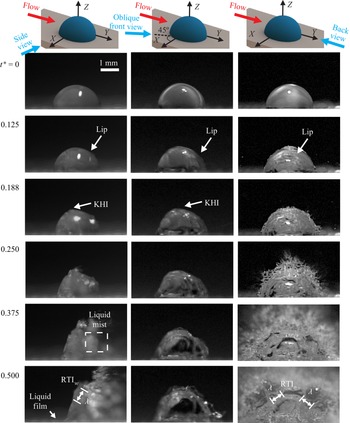
The deformation process of a hemispherical droplet with contact angle  $\theta =90^{\circ }$ is shown in figure 5 (also in supplementary movie 2). From the left column to the right columns are the results captured from the side view, the oblique front view and the back view, respectively. As the hemispherical droplet can be regarded as half of the spherical droplet, the experimental comparison between the hemispherical droplet and the spherical droplet will be further given in figure 7. Here we mainly focus on the morphological evolution of the hemispherical droplets. The hemispherical droplet and hydrophobic droplets are found to show similar morphologies in the early stage of deformation, including the occurrence of the ‘lip’ structure at the droplet leeward side (
 $t^*=0.125$), the growth of the K–H instability on the droplet equator (
 $t^*=0.188$) and the formation of liquid mist (
 $t^*=0.25$). However, from
 $t^*=0.375$, the evolution of the hemispherical droplet shows a remarkable difference with that of the hydrophobic droplet. Specifically, the hemispherical droplet does not have the ‘peak’ structure that exists at the windward side of the hydrophobic droplet. Instead, a thin liquid film appears at the tail of the hemispherical droplet on the solid wall, which is closely related to the boundary layer near the solid wall. At a later stage of deformation, the child droplets are peeled off from the main droplet. Moreover, obvious perturbation waves caused by RTI
 $_w$ and RTI
 $_c$ can be observed, as shown by the results from the side view and back view, respectively.
Deformation process of a hemispherical droplet captured from three views. From the left to right columns are the results taken from the side view, the oblique front view and the back view, respectively. The dimensionless time is marked on the left. The contact angle is  $\theta =90^{\circ }$. Here KHI denotes the K–H instability, RTI
 $_w$ denotes the R–T instability of the windward side, RTI
 $_c$ denotes the R–T instability of the circumference direction and
 $\lambda$ denotes the wavelength of perturbation.

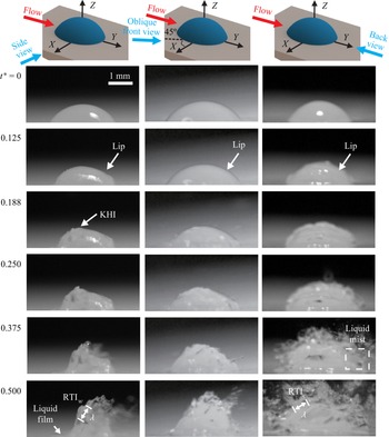
The deformation and breakup of a hydrophilic droplet are shown in figure 6 (also in supplementary movie 3), where the left, the middle and the right columns denote the pictures taken from the side view, the oblique front view and the back view, respectively. The shape of the hydrophilic droplet is like a cap with a much smaller height  $H$ compared with the hemispherical and hydrophobic droplets. Therefore, the relative ratio between the boundary layer thickness and the height of the droplet becomes larger, suggesting a more significant influence of boundary layer effect on the droplet evolution. It can be found that the morphological evolution of the hydrophilic droplet shows little difference with those of the hydrophobic and hemispheric droplets as
 $t^* \le 0.25$, which includes the occurrence of the ‘lip’ structure, the growth of the K–H instability and the formation of liquid mist. At the later stage of droplet deformation (e.g.
 $t^*=0.375$ and 0.5), the hydrophilic droplets also leave a liquid film on the droplet tail due to the boundary effect of the solid wall, which is similar to the evolution of the hemispherical droplet. Perturbation waves caused by RTI
 $_w$ and RTI
 $_c$ can be observed from the side and back views, respectively.
Deformation process of a hydrophilic droplet captured from three views. From the left to right columns are the results taken from the side view, the oblique front view and the back view, respectively. The dimensionless time is marked on the left. The contact angle is  $\theta =65^{\circ }$. Here KHI denotes the K–H instability, RTI
 $_w$ denotes the R–T instability of the windward side, RTI
 $_c$ denotes the R–T instability of the circumference direction and
 $\lambda$ denotes the wavelength of perturbation.

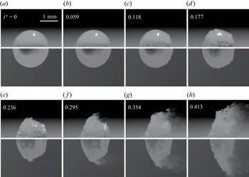
As the hemispherical droplet can be regarded as half of the spherical droplet from the geometrical view, we compare the deformation process of a hemispherical droplet with that of a spherical droplet. The results are shown in figure 7, under the same value of Weber number and Reynolds number. For the convenience of comparison, only the lower half of the spherical droplet is shown in the figure. At the early stage of droplet evolution (e.g.  $t^*=0 \sim 0.177$), there are not too many differences on the morphologies between the hemispherical droplet and the spherical droplet, and the droplets go through slight deformation with some perturbations on the surface. At
 $t^*=0.236$, the liquid film begins to occur on the solid wall for the hemispherical droplet. As the typical velocity of the liquid film is much smaller than that of the main droplet, the liquid film delays the movement of the windward side of the wall-attached droplet, especially at the position close to the wall (see
 $t^*=0.236 \sim 0.413$). As for the droplet evolution at the height direction, there seems no obvious differences on the deformation rate of the droplet height. The occurrence of liquid mist also presents a similar characteristic. The qualitative comparison in figure 7 proves the inhibition effect of the solid wall on the droplet deformation in the airflow direction.
Droplet breakup morphologies of a hemispherical droplet (a–d) and a spherical droplet (e–h) at  $We=497$ and
 $Re=19\,423$. Only the lower half of the spherical droplet is shown for comparison. The dimensionless time is also indicated in each graph.

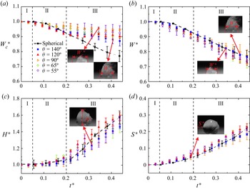
We also compare the evolutions of the wall-attached droplets with that of the spherical droplet quantitatively. Four typical parameters representing the droplet deformation are chosen here, including the droplet width  $W_C$, the droplet width
 $W$ that neglects the special structure caused by the wall effect (i.e. the ‘peak’ and the liquid film), the droplet height
 $H$ and the windward displacement
 $S$. The corresponding dimensionless forms of these parameters are defined by
 $W_{C}^{*}$,
 $W^*$,
 $H^*$ and
 $S^*$, which are calculated as
 \begin{equation} \left. \begin{aligned} W_{C}^{*} & =1+\frac{W_C-W_0}{D_0},\\ W^* & =1+\frac{W-W_0}{D_0},\\ H^* & =1+\frac{2(H-H_0)}{D_0},\\ S^* & =\frac{S-S_0}{D_0}, \end{aligned} \right\} \end{equation}
where  $W_0$,
 $H_0$ and
 $S_0$ are the droplet width, height and the windward position at the initial state,
 $D_0$ are the equivalent diameters of the droplet. The dimensionless parameters are sketched in the sub-graphs of figure 8.
Temporal evolutions of the dimensionless parameters reflecting the droplet deformation and breakup. The black square with a dashed line represents the spherical droplet, the symbols with different shapes and colours represent the hydrophobic, hemispherical and hydrophilic wall-attached droplets. (a) Comparison of the dimensionless width of droplets. (b) Comparison of the dimensionless width of droplets that neglect the special structure. (c) Comparison of the dimensionless height of droplets. (d) Comparison of the dimensionless windward displacement of droplets.

Figure 8 shows the temporal evolutions of  $W_{C}^{*}$,
 $W^*$,
 $H^*$ and
 $S^*$ of the wall-attached droplets with different wettabilities, and the case of a spherical droplet is also given for comparison. The parameters are all measured through multiple groups of experiments, and the error bars given accompany the average values. After the shock wave sweeps over the droplet, the droplet deforms gradually, and then child droplets are peeled off from the main droplet under the continuous acceleration of airflow, forming the liquid mist and filament. Based on the evolution of droplet morphology, we divide the breakup process into three main stages: the starting up stage (stage I), the deformation stage (stage II) and the breakup stage (stage III). In stage I the shock wave has just swept over the droplet. The droplet almost maintains its initial shape with only slight deformation and perturbation on the surface. The dimensionless time scale for stage I is roughly from 0 to 0.05. In stage II the K–H instability waves appear on the equator of the droplet. The windward and leeward side of the droplet deforms significantly due to the influence of high-speed airflow. A liquid sheet occurs at the edge of the windward side of the droplet, which gradually stretches in the airflow. The dimensionless time scale for stage II is roughly from 0.05 to 0.2. In stage III the sheet is fully stretched into liquid ligament, which further atomizes into child droplets with a much smaller size. The R–T instability fully develops at this stage due to the continuous acceleration of the gas–liquid surface. The typical interface structures of the wall-attached droplets with different wettabilities also appear at this stage. Specifically, the hydrophobic droplet presents ‘peak’ structures on both the windward and leeward sides, while the hemispherical and hydrophilic droplets leave a liquid film on the wall. The dimensionless time scale for stage III is roughly from 0.2 until full breakup of the droplet. The three stages are marked by dashed lines in figure 8.
Figure 8(a) shows the temporal evolution on the dimensionless droplet width  $W_C^*$. The situations of the wall-attached droplets with different wettabilities are denoted by symbols with different shapes and colours, and the case of the spherical droplet is denoted by the black solid squares with a dashed line. In stage I the width of the wall-attached droplets and the spherical droplet only show a tiny difference. However, the temporal evolutions of
 $W_C^*$ differ significantly between the wall-attached droplets and the spherical droplet in stages II and III. Specifically, the width of the spherical droplet decreases rapidly due to the extrusion of a high pressure zone on both the windward and leeward sides of the droplet, which leads to flatness of the droplet. However, the decreasing tendency on the width of the wall-attached droplets is much slower than that of the spherical droplet. This can be attributed to the appearance of a ‘peak’ structure for the hydrophobic droplets and the liquid film structure of the hemispherical and hydrophilic droplets. The physical reasons for the appearance of these structures will be further analysed in figure 9. Figure 8(b) further shows the temporal evolution on the droplet width
 $W^*$, without considering these special structures of the wall-attached droplets. Surprisingly, it is observed that the dimensionless width
 $W^*$ of the wall-attached droplets and the spherical droplet show good consistency. The results confirm that the deviation of the droplet width between the spherical droplet and the wall-attached droplets is caused by the special surface structures induced by the solid wall.
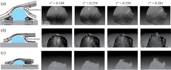
Sketches of the streamline and experimental deformation processes of wall-attached droplets with different wettabilities. (a) The hydrophobic droplet with contact angle  $\theta =140^{\circ }$, (b) the hemispherical droplet with contact angle
 $\theta =90^{\circ }$ and (c) the hydrophilic droplet with contact angle
 $\theta =65^{\circ }$.

Figure 8(c) shows the temporal evolution on the dimensionless height  $H^*$ of the droplets. It is clear that during the deformation and breakup stages, the value of
 $H^*$ keeps increasing, which is mainly caused by the formation of liquid mist at the droplet equator. Comparing the results between the wall-attached droplets and the spherical droplet, we find that the variation tendency of the height
 $H^*$ is very similar, indicating that the existence of the solid wall only has a tiny effect on the droplet deformation at the height direction. The reason for this can be explained according to the physical mechanism of liquid mist formation. Generally, there are two perceptions on the formation of liquid mist: the ‘thin layer refinement’ regime that is related to the K–H instability near the gas–liquid interface; and the ‘shear stripping’ regime that assumes a thin liquid layer with its thickness equal to the liquid boundary layer inside the droplet (Nicholls & Ranger Reference Nicholls and Ranger1969; Liu & Reitz Reference Liu and Reitz1997). In both regimes the generation of liquid mist is closely related to the local air velocity at the droplet equator. The air velocity affects the stripping intensity of subsequent child droplets. For the aerobreakup of wall-attached droplets under a certain Mach number, the air velocity maintains almost unchanged outside the wall boundary layer but decreases significantly inside the boundary layer. The thickness of the velocity boundary layer on the solid wall (denoted by
 $\delta _s$) can be calculated by
 \begin{equation} \delta _s=5 \sqrt{\frac{\mu _gx}{\rho _gU_g}}, \end{equation}
where  $x$ denotes the characteristic evolution length of the boundary layer. In our experiments
 $x$ is chosen as the distance between the edge of the test block and the windward side of the droplet, which is
 $x=5\, \textrm {mm}$. Here
 $U_g$ is the post-wave gas velocity and is calculated by the one-dimensional gas dynamics theory of (2.3). The dynamic viscosity
 $\mu _g$ and density
 $\rho _g$ of air at a temperature of
 $293 K$ are used. The calculated thickness of the velocity boundary layer is
 $\delta _s=0.133$ mm. Comparing the boundary layer thicknesses with the height of droplets with different wettabilities (see table 1), it is clear that a greater portion of liquid is located within the boundary layer as the contact angle gradually decreases. However, the height of most hydrophilic droplets is still significantly larger than the boundary layer thickness, suggesting that the boundary layer flow does not affect the local air velocity close to the equator of the wall-attached droplets. When the gas velocity at the droplet equator is consistent, the local deformation and stripping characteristic of the droplet equator show similar tendencies. Therefore, the dimensionless height of the wall-attached droplets with different wettabilities and the spherical droplet all present a similar variation.
Figure 8(d) shows the temporal evolution of the dimensionless windward displacement  $S^*$ of droplets. Similar to the analysis in figure 8(b), the special structure of wall-attached droplets is ignored. It is observed that the variation tendency of the windward distance of the wall-attached droplets with different wettabilities and the spherical droplet also show good consistency. It is notable that according to the variation tendency of
 $S^*$, we can calculate the accelerated speed of the windward surface and analyse the development of the R–T instability on the surface. The detailed analysis will be given in § 5.
4. Evolution of special structures on droplet surface
From the morphologies of wall-attached droplets, we have found the ‘peak’ structure on the windward and leeward sides of the hydrophobic droplet and the residual of the film at the tail of the hemispherical and the hydrophilic droplets, respectively. The ‘lip’ structure also occurs at the leeward side of the droplets. The mechanisms on the appearance and evolution of these typical structures are analysed in this section.
We study the flow field around the wall-attached droplets to reveal the formation mechanisms of the ‘peak’ structure and liquid film on the wall-attached droplets. Sketches of the streamlines around the wall-attached droplets under different wettabilities before the droplets present obvious deformation are shown in figure 9. For a hydrophobic droplet shown in figure 9(a), it is observed that there exists a standing vortex on the windward and leeward sides of the droplet. A stagnation point also exists at the top of the standing vortex on the droplet surface. The continuous extrusion of airflow on both sides of the stagnation point is supposed to contribute to the appearance of the ‘peak’ structure on the droplet windward and leeward sides. Moreover, a recirculation flow region forms at the droplet leeward side, which leads to a sudden reverse of air velocity near the droplet equator. Therefore, the liquid tends to roll up to form the ‘lip’ at the position of velocity reversion. However, for a hemispherical droplet shown in figure 9(b), the standing vortex does not exist close to the droplet. Instead, the streamlines are similar to that of the flow around a cylinder, in which a recirculation region forms behind the droplet. The recirculation flow contributes to the formation of the ‘lip’ structure at the droplet leeward side. As the velocity boundary layer exists at the solid wall, the liquid film can be formed at the tail of the droplet during its deformation and movement. For a hydrophilic droplet shown in figure 9(c), the overall structure of the streamline is similar to that of the hemispherical droplet. The streamlines pass over the hydrophilic droplet and form a recirculation region at the droplet leeward side. As the droplet height is smaller than those of the hemispherical droplet, the size of the recirculation region behind the hydrophilic droplet is also much smaller than that of the hemispherical droplet. The liquid film also exists on the wall, which is related to the boundary layer effect.
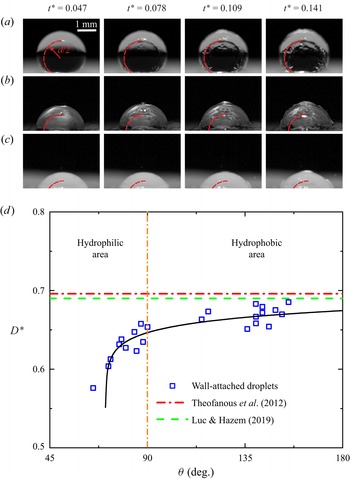
Apart from the surface evolution observed from the side view of the droplet, the deformation and perturbation growth on the droplet windward surface have also been investigated by previous studies (Joseph et al. Reference Joseph, Belanger and Beavers1999, Reference Joseph, Beavers and Funada2002; Theofanous et al. Reference Theofanous, Mitkin, Ng, Chang, Deng and Sushchikh2012). However, there are few studies considering the surface evolution at the leeward side of the droplet. As the surface structures of the hydrophobic, hemispherical and hydrophilic droplets are clearly observed from the back view (see figures 4, 5 and 6, respectively), the evolutions of the ‘lip’ structure on the droplet leeward side can be studied systematically. As we have stated in figure 9, the formation of the ‘lip’ structure is mainly caused by the reverse of the surface velocity close to the recirculation region. The protrusion of the surface then develops continuously in the later stage of droplet deformation. As the ‘lip’ structure appears, we study the temporal evolutions of annular ‘lip’ diameters for droplets with different wettabilities. The results are shown in figure 10(a–c), in which the red lines draw half of the outline of the annular ‘lip’ and  $d$ denotes the ‘lip’ diameter. During the deformation process of the droplet, it is observed that
 $d$ changes only slightly with an increase of time either for the hydrophobic droplet, the hemispherical droplet or the hydrophilic droplet. In order to compare the ‘lip’ diameters between different droplets, the dimensionless quantity
 $D^*$, which reflects the relative size between the annular ‘lip’ and the equivalent droplet diameter
 $D_0$, can be defined as
 \begin{equation} D^*=\frac{d}{D_0}. \end{equation}
Temporal evolutions of the ‘lip’ structure observed from the back view. (a) The hydrophobic droplet, (b) the hemispherical droplet and (c) the hydrophilic droplet. The red lines draw half of the profile of the ‘lip’ structure, and the diameter of the ‘lip’ is denoted by  $d$. (d) Dimensionless ‘lip’ diameter
 $D^*$ at different contact angles
 $\theta$. The dashed and dash-dotted lines represent previous experimental results for the spherical droplet.

Figure 10(b) shows the experimental values of  $D^*$ at different values of contact angle
 $\theta$. In order to show the variation tendency, the least square method is utilized to fit the data, as shown by the black solid line. Overall,
 $D^*$ maintains almost constant as
 $\theta >90^{\circ }$ but decreases significantly with
 $\theta$ when
 $\theta \le 90^{\circ }$. We also consider the cases of the spherical droplet according to the previous experimental studies (Theofanous et al. Reference Theofanous, Mitkin, Ng, Chang, Deng and Sushchikh2012; Luc & Hazem Reference Luc and Hazem2019). Through extracting the droplet profiles and calculating the ‘lip’ size, the corresponding results are given by the dashed and dash-dotted lines, respectively, showing that
 $D^*=0.693 \pm 0.003$ for the spherical droplet. For the wall-attached droplets in our experiments, we found that the size of the annular ‘lip’ of the hydrophobic droplet tends to a fixed value around 0.67, which is very close to the results of the spherical droplet. As the profiles of the hydrophobic droplets is analogous to the spherical droplet with its height much larger than the thickness of the wall boundary layer; therefore, the appearance and evolution of the ‘lip’ with
 $\theta >90^{\circ }$ are hardly affected by the boundary layer effect. The results of hydrophilic and hemispherical droplets gradually diverge from those of the spherical droplet. As the contact angle decreases, the height of the droplet decrease correspondingly, and the influence of the wall boundary layer becomes more obvious. The variation tendency of
 $D^*$ is consistent with the sketches of recirculation flow in figure 9, where the size of the recirculation region decreases significantly as
 $\theta$ decreases.
5. The R–T and K–H instabilities on droplet surface
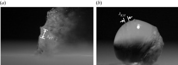
The R–T and K–H instabilities during the evolution of the wall-attached droplet are studied quantitatively. Figures 11(a) and 11(b) give the sketches of the wavelength of the R–T and K–H instabilities, respectively. As the unstable R–T and K–H waves are fully developed, we can measure the value of the distance between the wave crests or troughs as a wavelength (denoted by  $\lambda _{RT}$ and
 $\lambda _{KH}$, respectively). Multiple groups of unstable waves are measured and the average values of the wavelength can be calculated. It is notable that the R–T instability is a typical kind of instability that is caused by the continuous acceleration of the surface with different fluid densities on both sides. During the droplet aerobreakup, the R–T instability can lead to the piercing behaviour of the flattened windward surface. The high-speed gas flow over the droplet periphery also induces the R–T instability in the circumferential direction. The K–H instability is caused by the tangential velocity difference on both sides of the gas–liquid surface. The velocity difference at the surface near the equator leads to the strong shear force, resulting in the roll-up of the surface and the continuous stripping of small droplets.
Wavelengths measured on the droplet interface from the experimental results. (a) The R–T instability wavelength  $\lambda _{RT}$ and (b) K–H instability wavelength
 $\lambda _{KH}$.

Firstly, we consider the R–T instability on the windward side of the droplet. After the shock wave sweeps over the droplet, the droplet begins to accelerate in the post-wave air stream. The R–T instability waves occur at different scales and positions during the deformation of droplets. As the instability waves are fully developed, the large-scale R–T instability waves can be observed clearly (see figure 11a). For the previous studies considering the R–T instability of a spherical droplet, as the windward surface of the droplet gradually gets flattened in the later stage of aerobreakup, a two-dimensional theoretical analysis is given to predict the growth of perturbations on the surface (Joseph et al. Reference Joseph, Belanger and Beavers1999). Assuming that the direction of acceleration is perpendicular to the interface, the dispersion relationship of R–T instability can be given as
 \begin{equation} \omega _{RT}={-}k_{RT}^{2}\frac{\mu _l+\mu _g}{\rho _l+\rho _g}\pm \sqrt{k_{RT}\frac{\rho _l-\rho _g}{\rho _l+\rho _g}a-\frac{k_{RT}^{3}\sigma _l}{\rho _l+\rho _g}+k_{RT}^{4}\left( \frac{\mu _l+\mu _g}{\rho _l+\rho _g} \right) ^2}, \end{equation}
where  $\omega _{RT}$ and
 $k_{RT}$ denote the temporal growth rate and the wavenumber of perturbation,
 $\mu _l$ and
 $\mu _g$ denote the viscosities of the liquid and gas,
 $\rho _l$ and
 $\rho _g$ denote the densities of the liquid and gas,
 $\sigma$ denotes the surface tension of the droplet and
 $a$ denotes the accelerated speed of the windward surface. The equation can be simplified by considering the actual condition in our experiments where
 $\mu _g\approx 0$ and
 $\rho _l\gg \rho _g$. Thus, we can obtain the simplified dispersion relationship
 \begin{equation} \omega _{RT}={-}k_{RT}^{2}\frac{\mu _l}{\rho _l}\pm \sqrt{k_{RT}a-\frac{k_{RT}^{3}\sigma _l}{\rho _l}+k_{RT}^{4}\left( \frac{\mu _l}{\rho _l} \right) ^2}. \end{equation}
In order to compare the theoretical results with experiments, the dispersion relationship can be further non-dimensionalized by the characteristic time and length scales, which are
 \begin{equation} \left. \begin{aligned} \omega _{RT}^{*} & =\frac{D_0}{Ug}\sqrt{\frac{\rho _l}{\rho _g}}\omega _{RT},\\ k_{RT}^{*} & =D_0k_{RT}. \end{aligned} \right\} \end{equation}
The dimensionless form of the dispersion relationship can therefore be written as
 \begin{equation} \omega _{RT}^{*}={-}k_{RT}^{*^2}\boldsymbol{\cdot} \frac{c}{Re}\pm \sqrt{k_{RT}^{*}\frac{a^*}{c^2}-k_{RT}^{*^3}\frac{1}{c^2W\text{e}}+k_{RT}^{*^4}\boldsymbol{\cdot} \frac{1}{Re}}, \end{equation}
where the constant  $c=({\mu _l}/{\mu _g})\sqrt {{\rho _g}/{\rho _l}}$ and
 $a^*$ is the dimensionless accelerated speed. In our work the value of
 $a^*$ can be obtained through fitting the curves by
 $S^*=0.5a^*t^{*2}$ from the windward displacement of the droplet in figure 9(d). According to the dispersion relationship of (5.4), the variation of
 $We$ or
 $Re$ can affect the perturbation growth rate and manipulate the R–T instability. In this work, as the droplets with different wettabilities are unified with the same values of
 $Re$ and
 $We$, the difference between the growth rate curves is only decided by the value of
 $a^*$.
The curves of the dimensionless dispersion relationship are shown in figure 12(a), considering the situations of droplets with different wettabilities. As the windward displacement of droplets presents similar evolution characteristics (see figure 9d), the growth rate curves of wall-attached droplets with different wettabilities and the spherical droplet only show finite differences. Specifically, the wavenumber corresponding to the maximum value of growth rate (denoted by  $k_{RT\ max}^*$) changes slightly for different curves. As
 $k_{RT\ max}^*$ is decided, the dimensionless R–T wavelength corresponding to the most unstable R–T wave can be calculated by
 \begin{equation} \lambda _{RT}^{*}=\frac{2{\rm \pi}}{k_{RT\ max}^{*}}. \end{equation}
The R–T instability on the droplet surface. (a) Dimensionless perturbation growth rate ( $\omega _{RT}^{*}$) versus dimensionless wavenumber (
 $k^{*}$) for wall-attached droplets with different wettabilities and the spherical droplet. (b) Comparison between the experimental and theoretical results on the most unstable R–T wavelength at different contact angles.

Figure 12(b) gives a comparison between the theoretical predictions and the experimental measurements of  $\lambda _{RT}^{*}$ for different contact angles
 $\theta$ of wall-attached droplets. It is clear that when
 $\theta \ge 90^{\circ }$, the theoretical results generally present a good agreement with the experiments. However, as
 $\theta < 90^{\circ }$, the theoretical results are much larger than the experimental measurements. It is observed in experiments that the contact angle has a significant influence on the R–T instability when
 $\theta < 90^{\circ }$. The reason can be explained from the basic assumption of the R–T dispersion relationship, in which a plane gas–liquid interface is perpendicularly accelerated by the gas stream (Joseph et al. Reference Joseph, Belanger and Beavers1999). The windward side of the hemispherical and hydrophobic droplet can easily become flattened owing to the extrusion of a local high pressure region, thus satisfying the assumption in theoretical analysis. However, for the hydrophilic droplet with a much smaller height on the wall, the wall effect can present a stronger inhibition on the flattening of the droplet windward side and the development of the R–T instability, thus leading to the perturbation with a much smaller wavelength.
We also consider the K–H instabilities that occur at the equator of the droplet. Two existing theories that describe the K–H instability are utilized here, and the theoretical results are further compared with the experimental results. One typical theoretical model considers a parallel flow of both the gas and liquid phase and the discontinuous velocity profiles at the interface, as sketched in figure 13(a). In this model the boundary layer close to the interface is ignored and the flow vorticity equals zero invariably. The potential flow solution gives the dispersion relationship of the K–H instability as (Villermaux Reference Villermaux1998; Marmottant & Villermaux Reference Marmottant and Villermaux2004)
 \begin{equation} \omega _{KH}={\pm} \frac{k_{KH}}{\rho _l+\rho _g}\sqrt{\rho _l\rho _g\left( U_l-U_{ge} \right) ^2-\left( \rho _l+\rho _g \right) \sigma _l k_{KH}}, \end{equation}
where  $\omega _{KH}$ denotes the perturbation growth rate of the K–H instability,
 $k_{KH}$ denotes the wavenumber,
 $U_l$ denotes the liquid flow velocity and
 $U_{ge}$ denotes the local gas velocity at the equator of the droplet. According to the previous analysis considering the flow past a cylinder, an approximate relation of
 $U_{ge}=1.5U_g$ has been given (Jalaal & Mehravaran Reference Jalaal and Mehravaran2014). As the droplet velocity is much smaller than the gas velocity, the dispersion relationship can be simplified by considering the large velocity difference (
 $U_{ge}\gg U_l$) and density difference (
 $\rho _l\gg \rho _g$). After non-dimensionalizing the dispersion relationship by the characteristic time and length scales, i.e.
 \begin{equation} \left. \begin{aligned} \omega _{KH}^{*} & =\frac{D_0}{Ug}\sqrt{\frac{\rho _l}{\rho _g}}\omega _{KH},\\ k_{KH}^{*} & =D_0k_{KH}, \end{aligned} \right\} \end{equation}
we can obtain the dimensionless dispersion relationship
 \begin{equation} \omega _{KH}^{*}={\pm} k_{KH}^{*}\sqrt{2.25-k_{KH}^{*}\boldsymbol{\cdot} \frac{1}{We}}. \end{equation}
Therefore, the dimensionless wavelength corresponding to the maximum growth rate can be written as
 \begin{equation} \lambda _{KH}^{*}=\frac{2{\rm \pi}}{k_{KH\ max}^{*}}=\frac{3{\rm \pi}}{We}, \end{equation}
where  $k_{KH\ max}^{*}$ denotes the wavenumber at the maximum growth rate. Equations (5.8) and (5.9) show that the growth of the K–H instability is decided by the value of
 $We$.
Schematic diagram of two K–H instability models. (a) Schematic diagram of zero vorticity thickness theory. (b) Schematic diagram of thick vorticity thickness theory.

Figure 14(a) shows the dimensionless dispersion relationship curves for the K–H instability. For the wall-attached droplets with different wettabilities, the curves overlap under the same  $We$ (=641). The curve of the spherical droplet shows a small difference due to a slight variation in the Weber number (
 $We=653$, see table 1). Figure 14(b) shows the theoretical and experimental results of
 $\lambda _{KH}^*$ at different contact angles
 $\theta$. It can be seen that there are not many differences between the wall-attached droplets with different wettabilities, suggesting that the solid wall only has a negligible effect on the development of K–H waves. Quantitatively, the experimental results of the perturbation wavelength are much larger than the theoretical predictions.
The K–H instability on the droplet surface. (a) Dimensionless perturbation growth rate ( $\omega _{KH}^{*}$) versus dimensionless wavenumber (
 $k^{*}$) for wall-attached droplets with different wettabilities and the spherical droplet. (b) Comparison between the experimental and theoretical results on the most unstable K–H wavelength at different contact angles. The dashed and dash-dotted lines represent the theoretical prediction of zero vorticity thickness and thick vorticity thickness, respectively.

To reach a better comparison, another model that considers the boundary layer of the gas flow close to the interface is put forward, as sketched in figure 13(b). For this model with a certain boundary layer thickness  $\delta _g$, the dispersion relation is given by (Marmottant & Villermaux Reference Marmottant and Villermaux2004)
 \begin{equation} e^{{-}2\kappa}=\left[ 1-\left( 2\varOmega ^*+\kappa \right) \right] \frac{1+0.5\left( \rho _l/\rho _a+1 \right) \left( 2\varOmega ^*-\kappa \right)}{1+0.5\left( \rho _l/\rho _a-1 \right) \left( 2\varOmega ^*-\kappa \right)} , \end{equation}
where  $\kappa =k_{KH}\delta _g$ and
 $\varOmega ^*=\omega _{KH}\delta _g/( U_g-U_l ) -2\kappa {( U_g+U_l )}/{( U_g-U_l )}$. The boundary layer thickness
 $\delta _g$ is represented as
 \begin{equation} \delta _g=C\frac{D_0}{\sqrt{Re}}. \end{equation}
Here,  $C$ refers to a constant coefficient. Considering the situation
 $\rho _l\gg \rho _g$, the dimensionless wavelength of the most unstable K–H wave has been obtained by (Villermaux Reference Villermaux1998)
 \begin{equation} \lambda _{KH2}^{*}=\frac{\lambda _{KH2}}{D_0}=\frac{4{\rm \pi}}{3}C\sqrt{\frac{\rho _l}{\text{Re}\rho _g}}. \end{equation}
Figure 14(b) also shows the comparison between the experimental results and the theoretical predictions. A good agreement can be reached when choosing the certain value  $C=0.1$, suggesting that the model considering the boundary layer thickness (figure 13b) is more appropriate to predict the K–H instability at the droplet equator. It is notable that according to (5.11), the boundary layer thickness
 $\delta _g$ at
 $C=0.1$ equals
 $0.187$ mm, which is close to the boundary layer thickness at the solid wall (
 $\delta _s$) and very tiny compared with the size of the droplets.
6. Conclusions
This work investigates the morphologies and dynamics on the shock induced aerobreakup of wall-attached droplets through experiments and theoretical analyses. The wall-attached droplets with the same equivalent diameter but different wettabilities (hydrophobic, hemispherical and hydrophilic) are generated at the test section of the shock tube facility. The results obtained by the high-speed schlieren method show that the deformation of droplets is hardly affected by the impact of the shock wave. Through high-speed photography from three perspectives (the side view, the back view and the oblique front view), the droplet deformation and breakup in the post-wave air stream are studied systematically. The morphologies of wall-attached droplets show a remarkable difference from the free spherical droplet. Specifically, the hydrophobic droplet shows a ‘peak’ structures on the windward and backward sides, which is caused by the local standing vortex. The hemispherical and hydrophilic droplets develop a liquid film on the solid wall, which is closely related to the boundary layer near the wall. The dimensionless width, height and advancing distance of wall-attached droplets and the spherical droplet are compared quantitatively. It is found that the difference of droplet width between wall-attached droplets and the spherical droplet is mainly caused by the ‘peak’ structure and the liquid film. The growth of droplet height and the advancing distance of the droplet are similar between the wall-attached droplets and the spherical droplet, because the droplet deformation on the height direction and the acceleration of the windward surface are only slightly affected by the wall boundary layer. The ‘lip’ structure on the leeward side of the droplet is caused by the reverse of the velocity on the back of the droplet. Based on the experimental results captured from the back view, the size of the annular ‘lip’ under different contact angles of wall-attached droplets are studied. The ‘lip’ diameter of the hydrophobic droplets approximates that of the spherical droplet. With a decrease of contact angle, the ‘lip’ diameter gradually gets smaller due to the prominent influence of the wall effect. The R–T instability on the windward side and the K–H instability on the droplet equator are also studied. Simplified dispersion relationships are utilized to predict the growth of surface perturbations. The most unstable R–T wavelength predicted by theory agrees well with experiments for hydrophobic and hemispherical droplets. For the hydrophilic droplet, the wavelength measured from experiment is much smaller than the theoretical prediction. As the local velocity of airflow near the equator maintains almost the same, the droplet wettabilities are found to have a non-significant effect on the development of the K–H instability.
This study clarifies the wall effect on the deformation and breakup characteristics of wall-attached droplets with different wettabilities, which contributes to regulating the aerodynamic fragmentation of droplets in a high-speed airflow. Therefore, this research is expected to provide some guidance to engineering applications involving high efficiency spraying and the atomization of liquids. For possible avenues of future investigations, some significant issues that often appear in practical applications would be considered. For example, the surface morphology of a solid wall (e.g. the existence of interfacial curvatures or microstructures) would have great influences on the aerobreakup of droplets. Moreover, as non-Newtonian liquids are usually utilized in different conditions, the effect of liquid physical properties on the evolution of a wall-attached droplet should be studied in the future. As a result, the orientation of advanced progresses can strengthen the extension of the current study and provide more guidance to various applications.
Supplementary movies
See the dynamics of wall-attached droplets in movie 1, 2 and 3.
Supplementary movies are available at https://doi.org/10.1017/jfm.2023.612.
Funding
This work was supported by the National Natural Science Foundation of China (grant nos. 12027801, 12272372 and U2241255), Youth Innovation Promotion Association CAS (nos. 2018491, 2023477) and the Fundamental Research Funds for the Central Universities.
Declaration of interests
The authors report no conflict of interest.