Introduction
In geochemistry, the rare-earth elements (REEs) are typically defined as the lanthanides (lanthanum to lutetium) plus yttrium and scandium. In recent years their importance in a variety of ‘green’ technologies coupled with the current supply monopoly held by China (~80% of all mine production in 2016, Schulz et al., Reference Schulz, DeYoung, Seal and Bradley2017) has encouraged numerous efforts in other countries to identify their own REE reserves (Hatch, Reference Hatch2012). Weathering processes can serve to increase the grades of primary ores thereby forming supergene deposits; such processes are responsible for the development/enrichment of REE ore deposits such as Mt Weld, Western Australia (Lottermoser, Reference Lottermoser1990); Bear Lodge, Wyoming, USA (Andersen et al., Reference Andersen, Clark, Larson and Donovan2017); and the ion-adsorption clays of southern China and Madagascar (Kynicky et al., Reference Kynicky, Smith and Xu2012; Ram et al., Reference Ram, Becker, Brugger, Etschmann, Burcher-Jones, Howard, Kooyman and Petersen2019; Borst et al., Reference Borst, Smith, Finch, Estrade, Villanova-de-Benavent, Nason, M., Horsburgh, Goodenough, Xu and Kynicky2020). A range of factors and processes control REE distribution in weathering profiles. These include: the mineralogy of REE-hosting phases in the protolith and their resistance to weathering (Sanematsu et al., Reference Sanematsu, Kon and Imai2015; Santana et al., Reference Santana, Wall and Botelho2015; Bern et al., Reference Bern, Yesavage and Foley2017); local climate and topography (Aubert et al., Reference Aubert, Stille and Probst2001; Kanazawa and Kamitani, Reference Kanazawa and Kamitani2006); pH, Eh and the presence of inorganic ligands (Wood, Reference Wood1990; Bao and Zhao, Reference Bao and Zhao2008; Williams-Jones et al., Reference Williams-Jones, Migdisov and Samson2012); bulk mineralogy of the weathering profile itself, in particular the presence of clays and oxyhydroxides and the adsorption opportunities they present (Tripathi and Rajamani, Reference Tripathi and Rajamani2007; Bao and Zhao, Reference Bao and Zhao2008); secondary mineralisation (Berger et al., Reference Berger, Janots, Gnos, Frei and Bernier2014; Voutsinos et al., Reference Voutsinos, Banfield and Moreau2021); and biological activity (Taunton et al., Reference Taunton, Welch and Banfield2000; Goyne et al., Reference Goyne, Brantley and Chorover2010; Kraemer et al., Reference Kraemer, Kopf and Bau2015; Kraemer et al., Reference Kraemer, Tepe, Pourret and Bau2017).
Most prior work on the supergene enrichment of REE resources has been devoted to thick weathering profiles in tropical to subtropical areas that host economic REE mineralisation (Bao and Zhao, Reference Bao and Zhao2008; Yusoff et al., Reference Yusoff, Ngwenya and Parsons2013; Berger et al., Reference Berger, Janots, Gnos, Frei and Bernier2014; Sanematsu et al., Reference Sanematsu, Kon and Imai2015; Santana et al., Reference Santana, Wall and Botelho2015; Torró et al., Reference Torró, Proenza, Aiglsperger, Bover-Arnal, Villanova-de-Benavent, Rodríguez-Garćia, Ramírez, Rodríguez, Mosquea and Salas2017; Ram et al., Reference Ram, Becker, Brugger, Etschmann, Burcher-Jones, Howard, Kooyman and Petersen2019) and has focussed little on the in situ movement of REEs through the parent rock. The role of microbes and organic matter within weathering profiles has also been scarcely investigated, though numerous studies have demonstrated experimentally their ability to mobilise REEs through the production of siderophores, organic acids and other chelating agents (Goyne et al., Reference Goyne, Brantley and Chorover2010; Horiike and Yamashita, Reference Horiike and Yamashita2015; Kraemer et al., Reference Kraemer, Kopf and Bau2015; Corbett et al., Reference Corbett, Eksteen, Niu, Croue and Watkin2017; Kraemer et al., Reference Kraemer, Tepe, Pourret and Bau2017).
This work characterises the in situ movement of REEs through weathered rocks collected from a semi-arid environment and notes both inorganic and potentially organic controls on their liberation from REE-bearing magmatic minerals. While not completely analogous to the economically valuable weathering profiles of Madagascar and southern China rich in heavy REE (HREE), the decision to investigate rocks from a semi-arid locality has the advantage that the host rock has not been completely eroded allowing the direct in situ observation of the liberation and transport of REEs from their host minerals during early stages of weathering, in turn giving insights into their movement on the macro-scale through weathering profiles.
Geological background
This work focusses on samples collected from the Yerila Gneiss, which is located within the Mt Painter Domain, Flinders Ranges, South Australia, 29°52′33″S, 139°34′35″E. The Mt Painter Domain is split into two inliers, the Mount Painter and the Mount Babbage Inliers, consisting mainly of voluminous Mesoproterozoic granitic and felsic volcanic rocks (1576–1551 Ma), including the Yerila Gneiss located within the Mount Babbage Inlier. The Mt Painter Domain rocks crop out as a window in the Neoproterozoic to Cambrian rocks of the northern end of the Adelaide Geosyncline (Coats and Blissett, Reference Coats and Blissett1971; Teale, Reference Teale, Drexel, Preiss and Parker1993).
Following metamorphism to amphibolite facies locally during the Cambro–Ordovician Delamerian metamorphism (514–485 Ma; (Teale, Reference Teale, Drexel, Preiss and Parker1993; Foden et al., Reference Foden, Barovich, Jane and O'Halloran2001; Armit et al., Reference Armit, Betts, Schaefer and Ailleres2012; Weisheit et al., Reference Weisheit, Bons, Danisik, Elburg, Llana Funez, Marcos and Bastida2014), a second period of magmatism took place at ~440 Ma, characterised by granitic intrusions (Mudnawatana tonalite/trondhjemite, Paralana granodiorite, British Empire granite, Elburg et al., Reference Elburg, Bons, Foden and Brugger2003); the Mudnawatana tonalite intrudes the Yerila granite. The Mt Painter Domain cooled below 200°C at 330–320 Ma (McLaren et al., Reference McLaren, Dunlap, Sandiford and McDougall2002; Mitchell et al., Reference Mitchell, Kohn, O'Sullivan, Hartley and Foster2002) and slow cooling from >110°C occurred during the Late Carboniferous to Early Permian. Final cooling took place during the Palaeocene to the Eocene, however current relief and relatively high erosion rates are a result of on-going tectonic uplift at rates of 30–160 m Myr–1 due to range-front reverse faulting (Mitchell et al., Reference Mitchell, Kohn, O'Sullivan, Hartley and Foster2002; Brugger et al., Reference Brugger, Long, McPhail and Plimer2005; Quigley et al., Reference Quigley, Sandiford, Fifield and Alimanovic2007; Brugger et al., Reference Brugger, Wulser and Foden2011).
The Yerila Gneiss itself is a Mesoproterozoic (ca. 1545 Ma; Stewart and Foden, Reference Stewart and Foden2003) coarse-grained granitic rock with tabular K-feldspar phenocrysts set in a groundmass of quartz, plagioclase and biotite (Coats and Blissett, Reference Coats and Blissett1971; Wülser, Reference Wülser2009); foliation is typically well developed. In weathered samples this foliation forms the basis of fractures that assist water percolation into the rock. The intrusion of the Yerila gneiss was also associated with late-stage alkaline metasomatism that has been suggested as responsible for enriching the gneiss in REEs and other high-field-strength elements (Elburg et al., Reference Elburg, Bons, Dougherty–Page, Janka, Neumann and Schaefer2001; Stewart and Foden, Reference Stewart and Foden2003; Wülser, Reference Wülser2009).
The Yerila Gneiss is significantly enriched in U (~116 ppm), Th (423 ppm) and REEs (Wülser, Reference Wülser2009; Elburg et al., Reference Elburg, Andersen, Bons, Weisheit, Simonsen and Smet2012). The total concentration of REEs is variable across the gneiss but is typically 1000–3000 ppm, much higher than other granites in the Mt Painter Domain whose ΣREE concentrations vary from 50–700 ppm. The main REE-bearing minerals in the Yerila Gneiss are: allanite-(Ce) – [Ca, Ce][Al2,Fe2+](Si2O7)(SiO4)O(OH); titanite – CaTiSiO5; fluorocarbonates e.g. bastnäsite-(Ce) – (Ce(CO3)F), monazite-(Ce) – (CePO4); xenotime-(Y) – (YPO4); fluorapatite – Ca5(PO4)3F; and zircon – ZrSiO4.
Methodology and results
Bulk geochemistry
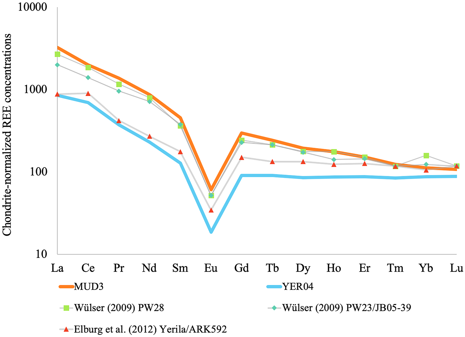
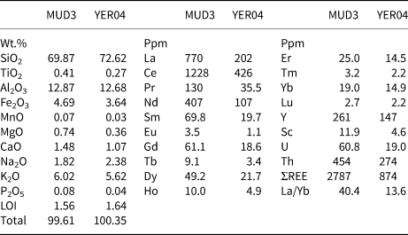
Two samples of Yerila Gneiss material are described here, designated YER04 and MUD3. Both samples were collected in situ and featured prominently weathered outer crusts on their exposed surfaces. YER04 was collected from an area containing an abundance of flora (primarily acacia, spinifex grass and saltbush) and MUD3 was collected from a barren area near the contact between the Yerila Gneiss and the Mudnawatana tonalite/trondhjemite. In both samples mineralogy and texture were typical of Yerila Gneiss material. Bulk geochemistry was obtained by inductively-coupled plasma mass spectrometry (ICP–MS) for trace elements and X-ray fluorescence (XRF) for major elements. For both analyses samples were crushed and milled with a tungsten carbide mill head forming a ~50 μm powder. In preparation for ICP-MS samples were digested at high pressure within sealed Teflon vessels at 170°C for 72 hours then solubilised and diluted with 2% HNO3. The analyses were performed using a Thermo iCAPO-c quadrupole ICP-MS at Monash University's School of Earth, Atmosphere and Environment and calibrated using external in-house standards. X-ray fluorescence analyses were performed at CODES, University of Tasmania using a PANalytical Axios Advanced X-ray Spectrometer and were prepared using platinum–gold crucibles at 1100°C with a lithium tetraborate–metaborate mix and LiNO3 being used as fluxes. Major-element results and REE concentrations are reported in Table 1; chondrite-normalised concentrations are reported in Fig. 1. These confirm the previously reported enrichment of REEs described in previous studies (Wülser, Reference Wülser2009; Elburg et al., Reference Elburg, Andersen, Bons, Weisheit, Simonsen and Smet2012).
Bulk chondrite-normalised REE concentrations for samples MUD3 and YER04. Data from prior analyses of the Yerila Gneiss are also reported.

Results of major-element analysis (wt.%) and bulk REE + U/Th concentrations (ppm) on samples MUD3 and YER04.

LOI – Loss on Ignition
Elemental distribution via synchrotron X-ray fluorescence microscopy (XFM)
Polished thin sections of both samples (~70 × 25 mm at 30 μm thickness) were made using quartz glass (Ted Pella, Inc, Redding, California). These thin sections were mapped using microXRF (beamsize ~2 μm) and the Maia 384 detector at the XFM beamline of the Australian Synchrotron (Victoria, Melbourne, Clayton; Howard et al., Reference Howard, de Jonge, Afshar, Ryan, Kirkham, Reinhardt, Kewish, McKinlay, Walsh and Divitcos2020). Overview maps of each sample were made at 18.5 kV, 4 μm pixel size, 0.22 ms per pixel dwell time and a velocity of 18 mm/s. Selected areas of interest were subsequently mapped in detail at 1–1.5 μm step pixel size, lower velocities (3–7 mm/s) and similar to longer dwell times from 0.22 to 0.33 ms per pixel. After collection, the megapixel synchrotron XRF data were analysed using GeoPIXE (Ryan et al., Reference Ryan, Etschmann, Vogt, Maser, Harland, Van Achterbergh and Legnini2005); standard foils (Pt, Mn and Fe) were used to constrain the detector geometry and efficiency; and to translate ion chamber counts to flux. Megapixel synchrotron XRF permitted rapid identification of REE-bearing minerals and highlighted in situ REE movement pathways (Li et al., Reference Li, Etschmann, Rae, Reith, Ryan, Kirkham, Howard, Rosa, Zammit, Pring, Ngothai, Hooker and Brugger2016).
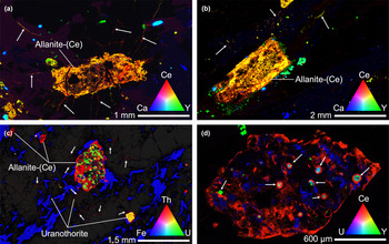
Several sites of interest from both samples are presented in Fig. 2. Limitations of the Maia detector (energy resolution of ~240 eV) precluded the individual identification of all REEs, though cerium and yttrium were used as proxies for light (LREE) and heavy (HREE) REE concentrations, respectively.
X-ray fluorescence maps of thin sections illustrating migration of REEs through micro fractures. Colour intensity is proportional to the concentration of the element of interest with intermediary colours indicating simultaneous presence of multiple elements at a given site. (a,b) selected sites of interest from MUD3 thin section – metamict and altered allanite-(Ce) (Orange grains) with radiating fractures acting as channel ways for mobilised REEs (some illustrated with arrows, red and yellow microfractures). Light green and blue–green grains are titanite and apatite, dark blue grains are mainly fluorite. (c) Overview of allanite grains and surrounding microfractures in sample YER04. A number of uranothorite grains (yellow) are visible, both as isolated grains and inclusions in the large central allanite grain. Thorium redistribution is also visible through cracks and along grain boundaries (white arrows) with a strong spatial association with allanite. Small (single pixel, ≤2 μm, visible as yellow) particles rich in uranium (±Th) are also visible throughout the sample. (d) Detail of altered euhedral allanite-(Ce) grain shown in (c), note the uranothorite inclusions (light blue–green) are associated with anomalous cerium-rich rings.

Images from XFM show that the major REE-bearing phase in both samples was allanite-(Ce). These magmatic allanite-(Ce) grains contain highly heterogeneous distributions of both major and minor elements (e.g. Fe, Ce, U and Th), with little of the original magmatic chemical zoning remaining. The XFM elemental images also highlight the movement of some elements, in particular LREE and Th, out of the original allanite-(Ce) host during alteration. LREEs (Fig. 2a) and Th (Fig. 2c) precipitated in micro-fractures throughout the samples. These fractures were almost invariably predominated by cerium (LREE) relative to yttrium (HREE). The greatest densities of REE-bearing micro-fractures were associated with altered allanite-(Ce) grains in both samples. Other REE-bearing phases, particularly, titanite, apatite and xenotime-(Y) tended to be less altered and generally did not appear to be sources for REEs in micro fractures. In sample YER04 a particular allanite-(Ce) grain was found to contain U–Th-rich circular structures (Fig. 2c,d). These structures invariably comprised an yttrium/HREE enriched core, a cerium/LREE enriched rim and a faint uranium-enriched halo. Similar structures were also identified isolated throughout YER04, however their density was greatest in the allanite grain mentioned. The remainder of this work focusses on the characterisation of this allanite-(Ce) grain, the circular structures observed within, a xenotime inclusion and the likely processes responsible for liberating REEs from them.
Mapping of Ce oxidation state
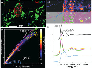
The oxidation state of Ce was mapped using the XANES (X-ray absorption near edge structure) imaging technique (Etschmann et al., Reference Etschmann, Ryan, Brugger, Kirkham, Hough, Moorhead, Siddons, De Geronimo, Kuczewski and Dunn2010, Reference Etschmann, Donner, Brugger, Howard, de Jonge, Paterson, Naidu, Scheckel, Ryan and Lombi2014). XANES stacks were generated by collecting synchrotron XRF maps at 109 irregularly spaced monochromator energies that spanned the Ce L 3-edge, with 0.5 eV steps across the edge. The intensities of the CeLα peak at each pixel in the synchrotron XRF map, at each monochromator energy, were extracted using GeoPIXE and used to construct XANES spectra at each pixel. To analyse this large dataset (the XANES stack contains 59,644 pixels), the intensity of the CeLα fluorescence band was plotted at different energies (Fig. 3b), corresponding to the characteristic peaks of Ce(III) (5.725 keV) and Ce(IV) (5.7365 keV; see reference spectra in Fig. 3e). Pixels from regions of different intensity ratios – corresponding in principle to different forms of Ce – were integrated (Fig. 3b). Their distributions are compared to the Ce map in Fig. 3c,d and the integrated XANES spectra are shown in Fig. 3e. The results show that Ce is present as Ce(III) in allanite-(Ce), including in the uranothorite-associated circles. Deviations from the expected intensity ratio at high intensities do not reflect changes in Ce oxidation state, but rather are due to self-absorption, i.e. result from high Ce concentrations in regions R3 and R4 (Hens et al., Reference Hens, Brugger, Etschmann, Paterson, Brand, Whitworth and Frierdich2019). In the spectra, this is reflected by a lowering of the intensity of the white line (intense peak in the spectrum of Ce(III) compounds) due to peak broadening (Fig. 3e). Cerium(IV) is found in the cracks radiating from the allanite-(Ce) grain; these cracks contain regions dominated mainly by either Ce(III) or Ce(IV).
Results of cerium XANES mapping. (a) Selected mapped area shown as a yellow rectangle. (b) Correlations among intensities of the CeLα line at CeLα fluorescence band at 5.725 keV [Ce(III)] and 5.7365 keV [Ce(IV)]. (c) Distribution of Ce in the XANES stack area. (d) Location of the pixels highlighted in (b). (e) XANES spectra of reference spectra (from Ram et al., Reference Ram, Becker, Brugger, Etschmann, Burcher-Jones, Howard, Kooyman and Petersen2019) and those extracted from the regions defined in (b).

Micro-textural analysis of allanite-(Ce) weathering
The micro-textures of the weathering allanite-(Ce) were characterised using scanning electron microscopy (SEM) imaging in conjunction with energy dispersive X-ray spectroscopy (EDS). Observations were performed on the carbon-coated YER04 thin section using a Jeol JSM 7001F Field Emission Gun (FEG) SEM equipped with an Oxford Instruments large area (80 mm2) EDS detector operated at a voltage range of 15–30 kV. The AZtec software was used for analysis of the EDS data. Secondary electron (SE) and back-scattered electron (BSE) micrographs were made to determine compositional contrasts (via BSE) and textural properties (via SE) of the REE-bearing phases.
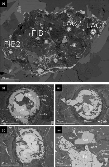
Detailed SEM micrographs of the main allanite-(Ce) grain presented in Fig. 2c,d are reported in Fig. 4. SEM observations of the circular structures (Figs 4b,c,d) revealed that they invariably exhibited a regular compositional zonation. All contained a core comprising rounded, yttrium-rich (~4 wt.%) uranothorite (Uth) grains. Surrounding these cores was a rim of REE-fluorocarbonate, most likely bastnäsite-(Ce) and/or synchysite-(Ce). The outer rim of this layer was particularly fibrous and occasionally extended into surrounding microfractures. The next outer layer was visible as a thin dark band in BSE images and consisted mostly of empty space that, locally, contained diamonds emplaced during thin-section polishing (e.g. Fig. 3c). Associated commonly with this porosity was a band of smooth dark grey carbonaceous clay. The final outer layer was typified by abundant nanocrystals (≤1 μm) of a U-rich mineral, visible as bright white flecks in BSE images and most likely to consist of uraninite (Ur); these uraninite nanocrystals are hosted within a carbonaceous groundmass similar in composition to the material directly circumscribing the fluorocarbonate rings. This general structure was consistent over all the observed circular structures. In the same allanite-(Ce) grain a xenotime-(Y) inclusion (designated FIB2, Fig. 4e) was also identified. As with the circular structures, it was associated with carbonaceous clay-like material; in contact with this material, the edges of the xenotime-(Y) grain rim appear to be diffuse rather than sharp (Fig. 4e). This is in contrast to the neighbouring bastnäsite-(Ce) grain, which displayed sharp edges despite also being in contact with the same carbonaceous material; this suggests some specific weathering interaction between the carbonaceous material and xenotime-(Y).
SEM micrographs of decomposed allanite-(Ce) grain and structures within: (a) overview of allanite-(Ce) grain containing anomalous Th- and REE-bearing circular structures with several sites of interest labelled; (b) detail of site LAC1; (c) detail of site FIB1, note the presence of polishing diamonds in the gap layer together with the carbonaceous clay; (d) detail of site LAC2; and (e) detail of site FIB2. Of particular interest is a xenotime-(Y) grain with ‘fuzzy’, possibly decomposing rim. Much of the surrounding dark material consists of highly carbonaceous, possibly organic material. Abbreviations: ‘Bst’ – bastnäsite-(Ce), ‘Carb’ – carbonaceous clay material, ‘Di’ – polishing diamonds, ‘REE-Fcb’ – REE fluorocarbonate, ‘Uth’ – Y-rich uranothorite, ‘Ur’ – uraninite nanocrystals and ‘Xen’ – xenotime-(Y).

Mineral dissection via Focused Ion Beam milling
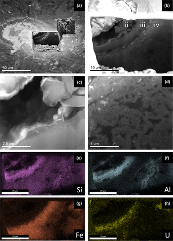
To investigate the three-dimensional structure of both the circular anomalies and the xenotime-(Y) and bastnäsite-(Ce) grains, two sites (FIB1 and FIB2) were milled using a FEI Quanta 3D FEG SEM focussed ion-beam (FIB-SEM). Milling was performed using a Ga beam at 30 kV acceleration voltage and with currents ranging from 30 to 0.1 nA. SEM imaging and X-ray mapping of the exposed surfaces were performed at 10–20 kV using an Apollo XP-SDD Detector to identify where various phases (particularly lanthanide and actinide-bearing ones) were concentrated. Images from sites FIB1 and FIB2 are presented in Fig. 5 and Fig. 6, respectively. Milling at site FIB1 showed that the circular structures were spheroidal and revealed the continuous nature of the compositional layers identified in prior SEM observations. Importantly, the FIB-SEM dissection confirmed that there was indeed a realm of empty space between the fluorocarbonate rim and carbonaceous outer rims (Fig. 5c). The empty space hence does not represent a polishing artefact, and may have been present in the fresh material or may be the result of dehydration of the C-rich layer in the vacuum of the SEM. Furthermore, the milled face allowed the textural characterisation of the surrounding carbonaceous material. Elemental assays via EDS confirmed their carbon-rich nature and suggested against an inorganic source due mainly to detection of comparatively low concentrations of oxygen – i.e. C:O ratios could not be reconciled by carbonate minerals.
SEM micrographs of site FIB1 (Fig. 3c). (a) Overview of milled site, pit depth was ~20 μm. Note the exposed face does not reach the uranothorite core. (b) Detail of the milled face, note the well-ordered layered structure. Layer ‘i’ is composed of the REE-fluorocarbonate described earlier, ‘ii’ is a cavernous layer partly in-filled with polishing diamonds, ‘iii’ is a layer of carbonaceous (~46 at.% C) material that also contains up to 10 at.% of both aluminium Al and silicon Si, ‘iv’ has an overall similar composition to ‘iii’ though with less silicon Si and aluminium Al (~5 at.%) and more iron Fe (5–10 at.%); this layer also contains numerous uraninite nanocrystals seen as embedded fibrous white flecks. ‘C’ and ‘D’ indicate the areas shown in detail in (c) and (d), respectively. (c) Detail of cavity, the grains on the upper right are diamonds emplaced during polishing. (d) Detail of the outer reaches of the circular structure, the white fibrous specks are uraninite nanocrystals The whole layer appears to be defined by abundant irregularly shaped cavities and a matrix of acicular/platy nanocrystals. (e–h) X-ray element-distribution maps of the face shown in (b). Note the distinct elemental compositions of the two carbonaceous layers ‘iii’ and ‘iv’ with ‘iii’ being rich in silicon and aluminium whereas ‘iv’ has more iron and uranium rich.

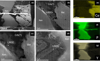
SEM micrographs of site FIB2. (a) Overview of milled face, imaged in BSE mode. ‘Xen’ – xenotime-(Y) grain of interest, ‘Bst’ – bastnäsite-(Ce) grain, ‘Crb(?)’ – carbonaceous phase composed primarily of carbon C with variable significant quantities of iron and aluminium. ‘B’ and ‘D’ indicate the areas shown in detail in ‘B’ and ‘D’, respectively. (b) Details of the carbon-rich layer surrounding the edge of the xenotime-(Y) grains, note its similarity to the detail of layer ‘iv’ shown in Fig. 4d. Note the texturally distinct halo of LREE-enriched carbonaceous material (LREE+) visible along the interface of the xenotime grain. EDS measurements recorded LREE concentrations on the order of 10 wt% each La, Ce and Nd in this material; a significant enrichment compared to the neighbouring xenotime-(Y) (~1 wt.% each). (c) Details of the edge of the xenotime-(Y) grain, note its highly porous structure associated with fibrous/platy nanocrystals. (d) Detail along another edge of the xenotime-(Y) grain, similar textures are observed here. The continuity of the porous LREE-enriched rim around the xenotime-(Y) grain seems to imply that the xenotime-(Y) is the source of these LREEs rather than the neighbouring bastnäsite-(Ce) grain. (e–g) X-ray element distribution maps of the site shown in (a); note the somewhat ‘fuzzier’ boundary of the xenotime grain relative to the neighbouring bastnäsite-(Ce) grain.

Milling at site FIB2 revealed a similar layer of carbonaceous material present along the entirety of the xenotime-(Y) grain's surface. Texturally and compositionally this material was very similar to that observed in layer ‘iv’ of the circular grain shown in Fig. 5. As in the circular structure, this interface was enriched particularly with LREEs (on the order of 10 wt.% each La, Ce and Nd) compared to the neighbouring xenotime-(Y) (~1 wt.% each). This LREE enrichment was observed along the whole grain boundary regardless of proximity to the neighbouring bastnäsite-(Ce) grain. This suggested that most if not all of the REEs present in this carbon-rich layer were sourced from the xenotime-(Y) grain rather than the neighbouring bastnäsite-(Ce) grain.
Rare-earth fractionation within a spheroid
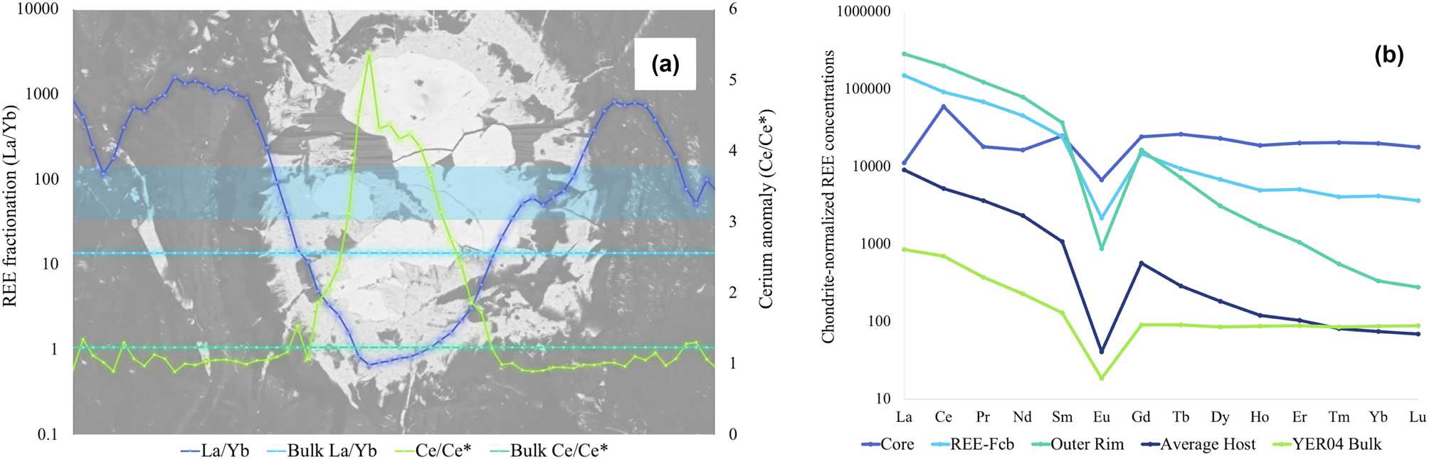
To investigate REE fractionation across the spheroids in more detail, a laser ablation inductively coupled mass spectrometry (LA-ICP-MS) traverse was conducted across one of the circular structures, specifically LAC2 (Fig. 4d). An 11 μm spot size was used for these traverses. Quantification was based on Longerich et al. (Reference Longerich, Jackson and Gunther1996), using silicon concentrations retrieved by SEM-EDS measurements of the ablated sites as an internal standard. As silicon concentrations were heterogeneous and the sampling volumes of EDS-SEM and LA-ICP-MS varied greatly, absolute REE concentrations were semi-quantitative only; however, this does not affect relative concentrations and normalised REE patterns, as atomic ratios are accurate; hence the data accurately record relative fractionation trends. Processed traverse data are reported in Fig. 7a, with chondrite-normalised (Sun and McDonough, Reference Sun and McDonough1989) plots from selected locations being reported in Fig. 7b. These data have also been plotted alongside results from the bulk geochemical assay of sample YER04 reported above. Cerium anomalies (Ce/Ce*) were quantified using chondrite-normalised measured concentrations of cerium, lanthanum and praseodymium input into equation 1.
 $$\rm Ce/Ce^\ast = \displaystyle{{Ce_{CN}} \over {\sqrt {La_{CN} \, \ast \, Pr_{CN}} }}$$
(a) LREE/HREE fractionation (quantified as La/Yb) and cerium anomalies across LAC2. La/Yb and Ce/Ce* values for the whole rock sample are presented as a background reference signal. The light-blue rectangle delineates the traverse path from which the data presented were measured. (b) Chondrite-normalised REE concentrations in the key compositional layers of LAC2. ‘Core’ – uranothorite core of the structure, ‘REE-Fcb’ – light fluorocarbonate layer, ‘Outer Rim’ – circumscribing carbonaceous material containing uraninite nanocrystals (layers ‘iii’ and ‘iv’ in Fig. 5b), ‘Average Host’ – Allanite-(Ce) grain hosting the spheroidal structure, ‘YER04 Bulk’ – concentrations of REEs reported in Table 1 and Fig. 1.

Results from the LA-ICP-MS traverse effectively illustrate two forms of REE-fractionation across LAC2. A strong LREE/HREE fractionation trend was observed, with LREEs being more enriched in the fluorocarbonate and carbonaceous rims relative to the uranothorite core that contained conversely a greater proportion of HREEs. In addition, a strong positive cerium anomaly was observed in the uranothorite core.
Discussion
The spheroidal structures and site FIB2 xenotime-(Y)/bastnäsite-(Ce) grains presented interesting examples of REE liberation, movement, fractionation and enrichment on a microscale among silicate, phosphate and carbonate minerals under similar conditions. To our knowledge no structures analogous to the spheroids observed in altered allanite-(Ce) have been reported in the literature, so here we summarise our observations and present hypotheses on their formation and significance with regards to REE surface geochemistry.
The spheroids were associated invariably with uranothorite inclusions (Fig. 2c,d). Further isolated examples of these spheroids were also observed outside this allanite-(Ce) grain suggesting their formation was not necessarily tied to the presence of allanite-(Ce), though the strong compositional association between uranothorite and allanite-(Ce) is what probably made the allanite-(Ce) in turn such a favourable host for the spheroids. As some of the uranothorite clearly formed under magmatic conditions (e.g. Fig. 2c), a high-temperature origin for the uranothorite cores of the spheroids is likely. Alteration of magmatic allanite-(Ce) may have occurred in the Mesoproterozoic as a result of a late magmatic, sodic metasomatic event believed to be responsible for enriching parts of the Yerila Gneiss with REEs (Elburg et al., Reference Elburg, Bons, Dougherty–Page, Janka, Neumann and Schaefer2001; Stewart and Foden, Reference Stewart and Foden2003; Wülser, Reference Wülser2009). Hydrothermal alteration by high-temperature fluorine-rich fluids would also explain the fluorocarbonate layer that circumscribes the uranothorite core.
On the other hand, the outer layers of the spheroids (i.e. Fig. 5b-iii-iv) with their carbonaceous clay-like, compositions are probably contemporary layers that formed during late weathering under surface or near-surface conditions. We suggest this material is probably a mix of organic matter and clay-like material derived from the decomposing allanite-(Ce); the exact source of the organic matter is unclear though cavities and an abundance of platy nanocrystals could suggest microbial activity. Although structures were observed of probable bacteriomorphic origin, the presence of carbon that cannot be reconciled solely with carbonates throughout the polymorphic layers ‘iii’ and ‘iv’ is a strong indication of a biological component. The abundance of uraninite nanocrystals in layer ‘iv’ is also strongly suggestive of bio-reduction (Newsome et al., Reference Newsome, Morris and Lloyd2014; Cumberland et al., Reference Cumberland, Douglas, Grice and Moreau2016, Reference Cumberland, Etschmann, Brugger, Douglas, Evans, Fisher, Kappen and Moreau2018), as the ability of bacteria to mediate the reduction of uranium and precipitation of uraninite nanoparticles is well documented (Fayek et al., Reference Fayek, Utsunomiya, Pfiffner, White, Riciputi, Ewing, Anovitz and Stadermann2005; Min et al., Reference Min, Xu, Chen and Fayek2005). This raises the possibility that the uranothorite micro-crystals within the spheroids also represent a product of weathering. Indeed, a positive Ce anomaly in the uranothorite cores suggests alteration under oxidising conditions in the presence of molecular oxygen, i.e. during weathering rather than hydrothermal alteration, where Ce(IV) is stable; under such circumstances, Ce is mostly immobile due to the low solubility of Ce(IV) oxide (cerianite-(Ce)) and hydroxides. As Ce(IV) was not detected in the uranothorite cores (Fig. 3), the positive Ce anomaly could be a fossilised indicator of prior exposure to more oxidising conditions with later conditions being more reducing, perhaps due to contact with organic material, or it may suggest preferential leaching of REEs other than Ce during alteration of the uranothorite (see Fig. 7b).
Siderophores and other organic ligands produced by microbes are well documented mobilisers (Chen et al., Reference Chen, Wang, Huang, Wu, Chen and Xu2000) and fractionators (Feng et al., Reference Feng, Ngwenya, Wang, Li, Olive and Ellam2011; Subashri et al., Reference Subashri, Dash, Balakrishnan and Sakthivel2013) of REE(III) ions. Some of these ligands can also mobilise Ce(IV) (Kraemer et al., Reference Kraemer, Kopf and Bau2015; Kraemer et al., Reference Kraemer, Tepe, Pourret and Bau2017) as well as actinides, in particular Th(IV) (Hirose and Tanoue, Reference Hirose and Tanoue2001; Desouky et al., Reference Desouky, El–Mougith, Hassanien, Awadalla and Hussien2016). The association of Ce(IV), Ce(III) and Th(IV) in small cracks radiating from allanite-(Ce) suggests low-temperature mobilisation of both Ce and Th during weathering in the presence of such ligands.
The driving mechanism behind REE(+Th,U) mobilisation during chemical weathering was either directly microbial or a by-product of organic acid/ligand interactions, or a combination thereof. The lack of any observed bacteriomorphic structures may reflect the fact that weathering occurred during periods of wetter climate (Quigley et al., Reference Quigley, Sandiford, Fifield and Alimanovic2007), or be a reflection of the episodic nature of microbial–mineral interactions in semi-arid environments (Fairbrother et al., Reference Fairbrother, Brugger, Shapter, Laird, Southam and Reith2012).
With all this in mind, we suggest that during weathering, organic ligands interacted with the fluorocarbonate rimmed uranothorite cores and mobilised REEs. On the basis of the chondrite-normalised REE concentrations reported in Fig. 7b it would appear that HREEs were removed more readily from these structures whereas LREEs were more prone to enrichment in the outer layers of these structures – such behaviour is consistent with EDS measurements of the xenotime around which significant LREE enrichment was observed despite xenotime being a HREE enriched mineral. LREE enrichment in the outer carbon-rich clay-like layers of both the spheroids and xenotime grain was probably driven by sorbtion onto charged clay surfaces as no distinct secondary REE minerals were identified around either. Such fractionation behaviour is consistent with prior observations that have noted a preference for LREEs to sorb to clay surfaces whereas HREEs tend to remain in solution, particularly in the presence of organic ligands (Wan and Liu, Reference Wan and Liu2006; Bao and Zhao, Reference Bao and Zhao2008; Murakami and Ishihara, Reference Murakami and Ishihara2008; Feng et al., Reference Feng, Ngwenya, Wang, Li, Olive and Ellam2011; Yusoff et al., Reference Yusoff, Ngwenya and Parsons2013).
Concurrent to this enrichment of LREEs in the outer carbon-rich layers of spheroids uranium was precipitated out as uraninite. Uranium was probably sourced from the uranothorite core where it was oxidised from U4+ to the mobile U6+ – probably under the same conditions that oxidised and immobilised cerium in the core, i.e. during weathering. Upon reaching the organic-rich outer layers of the spheroids this oxidised uranium was then reduced and precipitated in the outer layer forming the observed uraninite nanocrystals. Similar precipitation styles have been observed as a direct result of bacterial activity (Min et al., Reference Min, Xu, Chen and Fayek2005) though the lack of observed distinct bacteriomorphic structures around the spheroids suggests against direct (or at least recent) bacterial action. Reduced iron within the allanite-(Ce) may have been oxidised concurrently during weathering and acted as an electron source for uranium reduction.
During this chemical weathering, we hypothesise that the xenotime-(Y) grain at site FIB2 (Fig. 4e, 6) was subjected similarly to interaction with organic compounds. The carbon-rich rim is similar in both texture and composition to the outer carbon-rich layers of the spheroids. Both are carbon-rich, porous, defined by abundant nanocrystals and are enriched preferentially in LREEs relative to their ‘cores’.
Together these two carbon-rich sites reflect the trends and processes that define the distribution of REEs through the entirety of typical weathering profiles. They also potentially illustrate how the actions of the biosphere can serve to control this distribution. They both demonstrate the abilities of LREEs to be readily immobilised and concentrated whereas the HREEs are effectively leached. Preferential mobilisation of HREEs and middle REEs by organic ligands is well documented (McLennan and Taylor, Reference McLennan and Taylor1979; Brantley et al., Reference Brantley, Liermann, Bau and Wu2001; Pourret et al., Reference Pourret, Davranche, Gruau and Dia2007; Feng et al., Reference Feng, Ngwenya, Wang, Li, Olive and Ellam2011; Kraemer et al., Reference Kraemer, Kopf and Bau2015, Reference Kraemer, Tepe, Pourret and Bau2017) thus it is not unreasonable to suggest that HREE leaching from these structures could be mediated by organic means.
On the whole, the observations reported here have also highlighted differences in the weathering behaviours of allanite, REE-fluorocarbonates and REE-phosphates and the possible role that biological processes have in liberating REEs from these minerals. The xenotime and bastnäsite-(Ce) grains in Fig. 6 exemplify these differences with the xenotime displaying a far more active boundary both texturally and chemically. Indeed, most REEs outside either grain appear to be sourced from the xenotime. We suggest that this REE mobilisation and fractionation effect are a by-product of biological targeting of the phosphate present within xenotime – such behaviour has been documented for other REE-bearing phosphate minerals as well (Feng et al., Reference Feng, Ngwenya, Wang, Li, Olive and Ellam2011). Compared to the phosphate-containing xenotime the bastnäsite grain presents a less attractive target for microbial activity potentially explaining its far less active boundary. As a result, and regardless of being resistant to physical weathering, REE-phosphate minerals may still contribute significantly to the liberated REE budget of weathering profiles simply due to preferential biological action. REE mobilisation from allanite is probably a product of both physical weathering and indirect biological activity—the mobilisation of thorium and reduction of uranium under weathering conditions are best explained by biological activity and the organic ligands produced during microbial interactions with these elements (Hirose and Tanoue, Reference Hirose and Tanoue2001; Choudhary and Sar, Reference Choudhary and Sar2011; Newsome et al., Reference Newsome, Morris and Lloyd2014; Cumberland et al., Reference Cumberland, Douglas, Grice and Moreau2016; Desouky et al., Reference Desouky, El–Mougith, Hassanien, Awadalla and Hussien2016; Cumberland et al., Reference Cumberland, Etschmann, Brugger, Douglas, Evans, Fisher, Kappen and Moreau2018) are likely to be effective mobilisers of REEs as well. Thus, the presence of actinides may indirectly enhance the liberation of REEs due to microbial production of organic ligands intended to reduce their toxicological effects.
Conclusions
X-ray fluorescence microscopy observations have been able to confirm and directly observe the liberation and transport of REEs from allanite-(Ce) grains in samples of Yerila Gneiss material. Furthermore, they were able to highlight anomalous spheroidal structures and a xenotime-(Y) grain that upon further investigation using SEM and ICP-MS techniques were determined to contain a significant organic component. Along the outer edges of the spheroids and xenotime-(Y) grain significant enrichment and fractionation of REEs was observed, with LREEs being enriched relative to the parent minerals (uranothorite and fluorocarbonate in the case of the spheroids) and HREEs being depleted. This enrichment and fractionation was associated invariably with carbon rich, possibly organic, material. The presence of cerium anomalies and evidence for highly localised uranium oxidation and reduction around the spheroids additionally supports the hypothesis that the observed enrichment and fractionation of REEs most likely occurred during weathering, thus permitting the invocation of a biological control on this behaviour. Observed trends within the carbonaceous material were consistent with behaviours reported experimentally by previous workers. Depletion of HREEs is consistent with preferential leaching by organic ligands and LREE enrichment was consistent with their well-documented adsorption affinity to clays that the organic material resembled texturally. Altogether, this work has demonstrated both potential biological controls on REE distribution in weathering profiles and a microscope basis for the trends observed in more developed weathering profiles found elsewhere in the world.
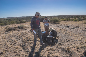
Frank (foreground), Alexander (kneeling) and Jeremiah Shuster on the field in the Mount Babbage Inlier, 28 May 2017.

Supplementary material
To view supplementary material for this article, please visit https://doi.org/10.1180/mgm.2021.4
Acknowledgements
This work is dedicated to Frank Reith (Fig. 8) whose breadth of knowledge and sunny disposition were a delight to behold and a great asset besides. The field of geomicrobiology has lost one of its best.
This research was in part undertaken on the XFM beamline at the Australian Synchrotron (M12890), part of ANSTO. This work was made possible by as whole swathe of excellent people who assisted with the multitude of analytical techniques used, and I would like to give most heartfelt thanks to them all:
Jeremiah Shuster, University of Adelaide; David Paterson, Australian Synchrotron; Junnel Alegado, Andrew Frierdich, Rachelle Pierson and Massimo Raveggi of the School of Earth Atmosphere and Environment, Monash University; Flame Burgmann, Amelia Liu and Renji Pan of the Monash Center for Electron Microscopy; Weihua Liu, CSIRO; and Sean Johnson and Jay Thompson, University of Tasmania.
This paper additionally benefitted from the feedback of two anonymous reviewers and the editorial guidance of Stuart Mills.