I. INTRODUCTION
Hierarchical mesoporous zeolites have attracted considerable attention from both academic and industrial points of view due to their promising catalytic properties for the reactions involving bulky molecules.Reference Davis1 Such hierarchical materials exhibit integrated superiorities of shape selectivity and acidic property inherited from the microporous structures of zeolites and efficient mass transfer benefited from the mesoporous structures.Reference Perez-Ramirez, Christensen, Egeblad, Christensen and Groen2–Reference Hartmann4 Various approaches for the synthesis of hierarchical mesoporous zeolite have been demonstrated, such as dealumination,Reference Triantafillidis, Vlessidis, Nalbandian and Evmiridis5 desilication,Reference Groen, Moulijn and Perez-Ramirez6 recrystallization of zeolites,Reference Ordomsky, Murzin, Monakhova, Zubavichus, Knyazeva, Nesterenko and Ivanova7 assembly of zeolite nanocrystals,Reference Liu, Zhang and Pinnavaia8,Reference Liu, Zhang and Pinnavaia9 soft template methods,Reference Choi, Cho, Srivastava, Venkatesan, Choi and Ryoo10–Reference Mukti, Hirahara, Sugawara, Shimojima and Okubo15 and confined synthesis in hard templates.Reference Schmidt, Madsen and Jacobsen16–Reference Yang, Xia and Mokaya18 In comparison with the other approaches, confined synthesis of hierarchical zeolites in hard templates provides a versatile means for introducing mesoporous structure to zeolites with controllable morphologies and topologies.
In our recent work, three-dimensionally ordered mesoporous-imprinted (3DOm-i) single-crystal MFI has been synthesized through confined growth within a three-dimensionally ordered mesoporous (3DOm) carbon template by a steam-assisted crystallization (SAC) method,Reference Fan, Snyder, Kumar, Lee, Yoo, McCormick, Lee Penn, Stein and Tsapatsis19 and 10–40 nm monodisperse nanocrystals of silicalite-1 (MFI topology) have been produced through the disassembly of the 3DOm-i silicalite-1.Reference Lee, Zhang, Stoeger, Malek, Fan, Kumar, Yoo, Al Hashimi, Penn, Stein and Tsapatsis20 In the synthesis process, incipient-wetness technique was used to ensure that the synthesis solution was introduced within the voids of the 3DOm carbon template, and SAC method was used to limit the nucleation and crystal growth within the confined space. To further expand the list of the available 3DOm-i zeolites, the combination of multiple hydrothermal (MHT) synthesis method with the confined synthesis approach has been explored. Various 3DOm-i zeolites, including BEA, LTA, FAU, and LTL, have been successfully synthesized from the approach.Reference Chen, Wydra, Zhang, Lee, Wang, Fan and Tsapatsis21 In this approach, zeolites were subsequently grown within 3DOm carbon by seeded growth under conventional hydrothermal conditions. Confining the zeolite growth within the carbon template was achieved by providing fresh synthesis solution for the seeded growth and timely removal of the crystals formed outside the carbon template. A success in the synthesis of 3DOm-i zeolites from this approach requires a control on multiple synthesis parameters including temperature, synthesis time, cycles of seeded growth and so on.
Both SAC and MHT approaches can control nucleation within the carbon template, and crystal growth was processed by propagation from cage to cage through the connecting windows within the 3DOm carbon. Although it is obvious that the mesoporous structure of the formed 3DOm-i zeolites is closely related to the 3DOm carbon template, quantitative information regarding mesoporous structural evolution from the starting material, silica colloidal crystals, to 3DOm-i zeolites is still missing. Understanding the replication process in detail could provide insights into the crystallization mechanism of zeolites under such conditions, contributing on tuning the catalytic properties, morphologies, topologies, and mesopore structures of the hierarchical zeolites formed by the confined synthesis approach. Therefore, in this study, a thorough investigation of structure replication and growth development of 3DOm-i zeolites during confined synthesis was carried out, and 3DOm-i BEA zeolites with a certain range of Si/Al ratio were prepared by tuning the amount of Al in the initial precursor solutions and optimizing the synthesis conditions.
II. EXPERIMENTAL PROCEDURE
A. Synthesis of size-tunable silica nanoparticles and 3DOm carbon
Silica nanoparticle sols were synthesized, as described in previous reports,Reference Fan, Snyder, Kumar, Lee, Yoo, McCormick, Lee Penn, Stein and Tsapatsis19,Reference Davis, Snyder, Krohn and Tsapatsis22–Reference Yokoi, Sakamoto, Terasaki, Kubota, Okubo and Tatsumi24 by hydrolysis of tetraethyl orthosilicate (TEOS, 98%, Sigma-Aldrich) in aqueous solutions of basic amino acid lysine (Sigma-Aldrich). Ten and twenty nanometer silica nanoparticle sols were prepared from the synthesis solution with the molar composition of 60 SiO2:1.2 lysine:9500 water:240 ethanol at the desired temperatures (60 °C for 10 nm and 90 °C for 20 nm silica particles) under continued magnetic stirring at 500 rpm for 48 h. Silica nanoparticle sols of 35 nm were prepared by a seeded growth technique, in which 20 nm silica nanoparticles were used as seeds. Subsequent repeated addition of TEOS, followed by growth at 90 °C for 24 h under vigorous stirring, was carried out 2 times to increase the particle size to 35 nm. The final molar compositions were 150 SiO2:1.2 lysine:9500 water:600 ethanol.
3DOm carbons were made by following the method reported by Yokoi et al.Reference Yokoi, Sakamoto, Terasaki, Kubota, Okubo and Tatsumi24 We further modified the method for making 3DOm carbons with larger cages.Reference Fan, Snyder, Kumar, Lee, Yoo, McCormick, Lee Penn, Stein and Tsapatsis19 In the process, silica colloidal crystal templates were formed by evaporation of the water from the lysine–silica nanoparticle sols in an oven at 70 °C for 24 h. After calcination of the product in a furnace at 550 °C for 12 h, furfuryl alcohol (Aldrich) and oxalic acid (Aldrich) were impregnated into the space among the packed silica nanoparticles for replication. The resulting product was heated to 90 °C for 1 day to allow the polymerization of furfuryl alcohol, then placed in flowing N2, first at 200 °C for 3 h, to cure the polymer, and then heated at 900 °C for another 3 h to carbonize the polymer. The template silica nanoparticles were dissolved in 6 M KOH solution (Aldrich) at 180 °C for 3 days to yield the mesoporous carbon replica, which was then thoroughly washed with deionized water to near neutral pH.
B. Confined synthesis of 3DOm-i zeolites by MHT method
3DOm-i zeolites were prepared within 3DOm carbon by MHT synthesis as described in our previous report.Reference Chen, Wydra, Zhang, Lee, Wang, Fan and Tsapatsis21 For making 3DOm-i BEA zeolites, a synthesis solution with a molar composition of 25 SiO2:x Al2O3:4.5(TEA)2O:0.35 Na2O:330 H2O was prepared by dissolving LUDOX HS-30 (30 wt% Aldrich) with tetraethylammonium hydroxide (TEAOH, 35 wt% Alfa Aesar) and NaOH at room temperature with stirring. After LUDOX HS-30 was dissolved, aluminum isopropoxide (98%, Aldrich) was added to the solution. The solution was aged for 24 h at room temperature with stirring, and then filtered using a 200 nm syringe filter. The Si/Al ratio of the synthesis solutions was systematically changed from 25 to 100 by adjusting x in the composition. Detailed chemical compositions and synthesis conditions are shown in Table S1. For making 3DOm-i MFI zeolites, the synthesis solution with a molar composition of 20 SiO2:9 TPAOH:8100 H2O was prepared by mixing TEOS (98%, Aldrich) with tetrapropyl ammonium hydroxide (1 M, TPAOH, Aldrich) and DI water. Further, the synthesis solution was aged for 12 h at room temperature with stirring, and then filtered using a 200 nm syringe filter.
In a typical MHT synthesis, 0.4 g of 3DOm carbon was immersed in 25 ml of the synthesis solutions prepared above. Followed by sealing in the Teflon-lined stainless steel autoclave, the mixture was heated at 100 °C, for 4 days to make 3DOm-i BEA with a designed Si/Al ratio of 50 and 100 °C, for 12 h to make 3DOm-i MFI zeolites, respectively. After taken out from the autoclaves, the samples were washed by filtration with DI water to remove the zeolite crystals formed outside of the carbon template, and then re-immersed into a freshly prepared synthesis solution for the second synthesis cycle. The synthesis cycles were repeated four and eight times to prepare 3DOm-i BEA and 3DOm-i MFI zeolites, respectively. The carbon templates were removed by calcination at 550 °C for 12 h.
C. Confined synthesis of 3DOm-i Al-ZSM-5 zeolites by SAC method
3DOm-i Al-ZSM-5 zeolites were prepared within 3DOm carbon by the SAC method used in our previous studies.Reference Fan, Snyder, Kumar, Lee, Yoo, McCormick, Lee Penn, Stein and Tsapatsis19,Reference Lee, Zhang, Stoeger, Malek, Fan, Kumar, Yoo, Al Hashimi, Penn, Stein and Tsapatsis20 In a typical SAC synthesis of 3DOm-i Al-ZSM-5, a clear solution including TPAOH (40%, Alfa Aesar), aluminum isopropoxide, NaOH, DI water and ethanol was added into 3DOm carbon by incipient wetness impregnation. To minimize the zeolite formation outside the 3DOm carbon, the volume of SDA solution added within the 3DOm carbon was equal to the pore volume of the 3DOm carbon template determined by nitrogen adsorption measurement. After evaporating the ethanol from the 3DOm carbon at room temperature, TEOS was added to the mixtures. Thereafter, the impregnated 3DOm carbons were kept at room temperature for 3 h before heating at 90 °C for 120 h or at 180 °C for 48 h for crystallization. The composition of the impregnated synthesis sol was 50 SiO2:0.5 Al2O3:9 TPA2O:0.15 Na2O:390 water:180 ethanol. The carbon templates were removed by calcination at 550 °C for 12 h.
D. Characterization
Wide-angle x-ray diffraction (XRD) patterns were collected on a Bruker-AXS D5005 x-ray diffractometer with a Cu Kα radiation. Small-angle x-ray diffraction (SAXD) measurements were taken on a home-built pinhole SAXS line with a sample-to-detector distance of 238 cm using Cu Kα radiation, and data were collected for 120 s. Scanning electron microscopy (SEM) images were collected on a Hitachi S-900 instrument with a field-emission gun operated at 3.0 kV, and the samples were coated with Pt (approximately 10 Å). Transmission electron microscopy (TEM) was performed on an FEI Tecnai T12 TEM operating at 120 kV and an FEI Tecnai G2 F30 TEM operating at 300 kV, and all TEM images were captured by charge-coupled device cameras. The samples for the TEM study were prepared on a copper grid with a few droplets of zeolite suspensions. Nitrogen adsorption and desorption experiments were performed on a Quantachrome Autosorb-1 system at 77 K. The samples were degassed at 250 °C for 12 h before the measurement. Si and Al contents of zeolites were collected by inductively coupled plasma optical emission spectroscopy (ICP-OES, Galbraith Laboratories).
III. RESULTS AND DISCUSSION
A. 3DOm-i zeolites synthesized by MHT and SAC methods
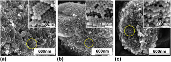
Our previous studies have revealed that 3DOm-i zeolites can be synthesized within 3DOm carbon. The cages of 3DOm carbon were interconnected with other cages through windows, exhibiting the close packing structure. The SAXD patterns of the silica colloidal crystals and 3DOm carbon confirmed that a face centered cubic structure was the dominant arrangement, reflecting that each cage within the 3DOm carbon could interconnect with the other 12 adjacent cages.Reference Cychosz, Guo, Fan, Cimino, Gor, Tsapatsis, Neimark and Thommes25 It was shown that the highly interconnected structure played a critical role in confining zeolite growth within the carbon template as well as allowing the zeolite nuclei formed in a cage to propagate to the adjacent cages through the windows. We have developed two methods to grow zeolites within the 3DOm carbon, which are MHT and SAC methods. In the MHT method, zeolites were subsequently grown within the 3DOm carbon by seeded growth under conventional hydrothermal conditions. Zeolite growth within the carbon template was achieved by providing fresh nutrient solutions to 3DOm carbon for the seeded growth and following timely removal of the crystals formed outside of the carbon template. On the other hand, the zeolite synthesis sol was impregnated within the 3DOm carbon by incipient-wetness technique in the SAC method. The nucleation and confined growth of zeolite crystals within the 3DOm carbon occurred under hot steams avoiding direct contact of water solution to the 3DOm carbon. It was proved that both MHT and SAC methods could produce zeolites with a 3DOm-i structure. The ordered packing structure of the spherical zeolite elements can be observed in the SEM images of 3DOm-i BEA [Fig. 1(a)] and 3DOm-i MFI [Fig. 1(b)] synthesized by the MHT method, and 3DOm-i Al-ZSM-5 [Fig. 1(c)] synthesized by the SAC method. The insets of Figs. 1(a), 1(b), and 1(c) show high magnification images of the 3DOm-i zeolite crystals revealing closely packed spherical elements.
SEM images of (a) 3DOm-i BEA and (b) 3DOm-i MFI synthesized by MHT method, and (c) 3DOm-i Al-ZSM-5 synthesized by SAC method.

B. Compression of 3DOm structures
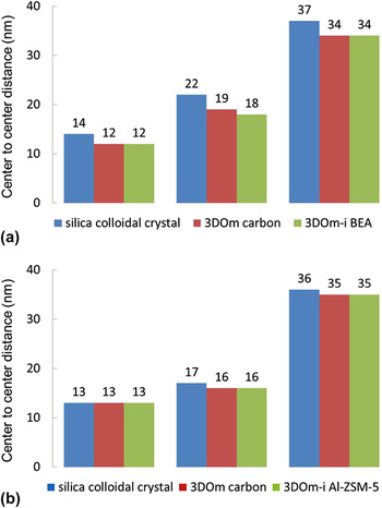
In both MHT and SAC synthesis approaches, the 3DOm structure was replicated two times: the steps from silica colloidal to 3DOm carbon and 3DOm carbon to 3DOm-i zeolites. A perfect replication may deliver the exact three-dimensional structure of the silica colloidal crystals to the final 3DOm-i zeolite crystal arrangements. However, it was shown that the 3D mesopore structure of the silica colloidal crystal was not completely same with the 3DOm-i zeolites. SAXD (Fig. 2) suggested that the center-to-center distances of the final 3DOm-i zeolites were close to the ones of the 3DOm carbon templates but smaller than the silica colloidal crystals. In case of samples with a spherical element size of 10 and 20 nm, a deviation of 0–2 nm between the 3DOm-i zeolites and the silica colloidal crystals was observed, while such deviation increased to 1–3 nm for 35 nm 3DOm-i zeolite. Thus, it was evident that compression of 3DOm structures occurred during a replication step from 3DOm silica to 3DOm carbon. Considering carbonization temperature above 800 °C, the compression may occur by sintering effects.Reference Wang and Liu26,Reference Xia and Mokaya27
Comparison of center-to-center distances of (a) 3DOm-i BEA synthetized by MHT method and (b) 3DOm-i Al-ZSM-5 synthetized by SAC method with those of the corresponding silica colloidal crystals and 3DOm carbon.

C. Mesopore deviation during structure replication
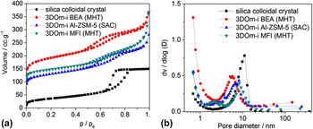
Besides the differences in center-to-center distances of the spherical elements, the mesopore morphologies between silica colloidal crystals and the replicated 3DOm-i zeolites were dissimilar, revealed by nitrogen adsorption-desorption experiments. Figure 3(a) shows the nitrogen adsorption isotherms of 35 nm silica colloidal crystals and the replicated 35 nm 3DOm-i zeolites. Although the isotherms revealed the similar type IV, the hysteresis generated by the mesoporosity between silica colloidal crystals and the replicated 3DOm-i zeolites demonstrated obvious diversities in shapes. A typical H2 type hysteresis was observed in the nitrogen adsorption isotherms of silica colloidal crystals, indicating a perfect closest packing structure, on the other hand, a transformative H2 hysteresis was found in the nitrogen adsorption isotherms of 3DOm-i zeolites, reflecting more irregular mesopore morphologies caused by the imperfect filling of the carbon template during the confined growth.
(a) Nitrogen adsorption-desorption isotherms and (b) BJH mesopore size distributions from adsorption isotherms of 35 nm silica colloidal crystal and the corresponding replicated 3DOm-i zeolites.

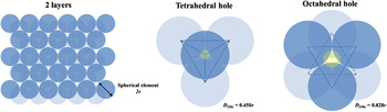
For a closest packing structure, there may be two kinds of holes generated by the packing of spherical elements (as shown in Fig. 4). The tetrahedral hole is formed by four spherical elements touching each other, while the octahedral hole is formed by six spherical elements. The diameters of the largest spheres that can be placed in the tetrahedral (D (th)) and octahedral hole (D (oh)) without pushing spherical elements apart are 0.450r and 0.828r, respectively, where r is the radius of spherical elements.
Schematic of a closest packing structure and its tetrahedral and octahedral holes.

Comparison of mesopore sizes between silica colloidal crystals and the replicated 3DOm-i zeolites with various sizes (10, 20, and 35 nm) of spherical elements is shown in Fig. 5. As a reference, the D (th) and D (oh) of silica colloidal crystals and the replicated 3DOm-i zeolites were calculated from the center-to-center distances determined by small-angle XRD patterns (as shown in Table S2), and the distributions of mesopore sizes were obtained by BJH model from adsorption isotherms [as shown in Fig. 3(b)]. It was found that the mesopore sizes of silica colloidal crystals and the corresponding replicated 3DOm-i zeolites were both increased as spherical element sizes. The mesopore sizes of silica colloidal crystals were located between D (th) and D (oh), close to the average value of D (th) and D (oh). The mesopore sizes of 10 and 20 nm 3DOm-i zeolites (both 3DOm-i BEA and 3DOm-i Al-ZSM-5) were larger than that of the corresponding silica colloidal crystal, and the mesopore sizes of 10 and 20 nm 3DOm-i Al-ZSM-5 zeolites were even larger than the diameters of their octahedral holes (D (oh)) [Fig. 5(a)]. This represented that mesopores larger than D (oh) were generated during the confined growth. Considering zeolite growth limitation of zeolite and diffusion limitation of nutrient through small windows, the mesopores may be originated from incomplete filling of cages of 3DOm carbon. On the other hand, the mesopore sizes of 35 nm 3DOm-i zeolites (both 3DOm-i BEA and 3DOm-i Al-ZSM-5) were smaller than that of the corresponding silica colloidal crystal. As the pore size of carbon templates increases, leading to 3DOm-i zeolite exhibiting smaller mesopore sizes because of the shrinked cage size of 3DOm carbon originated from sintering effects, this reflect an incomplete effect that becomes diminished. Moreover, unlike 3DOm-i Al-ZSM-5 by SAC, the mesopore size of 35 nm 3DOm-i BEA zeolite by MHT was even smaller than the diameter of its tetrahedral hole (D (th)) [Fig. 5(b)], which indicated a better filling of 3DOm carbon benefitted by the easier nutrient mass transfer from liquid solutions of the MHT method and the intergrowth habitus of BEA zeolites.Reference Newsam, Treacy, Koetsier and Gruyter28 Table S2 summarizes the relevant textural data of silica colloidal crystals and the corresponding replicated 3DOm-i zeolites.
Mesopore sizes of silica colloidal crystals and the corresponding replicated (a) 3DOm-i BEA zeolites synthetized by MHT method and (b) 3DOm-i Al-ZSM-5 zeolites synthetized by SAC method.

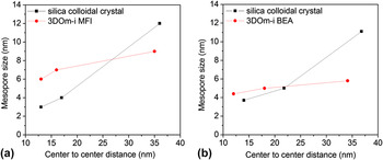
Moreover, the resulting structures of 35 nm 3DOm-i zeolites were not related to the synthesis method (MHT or SAC), but depended on the microstructure of zeolites. For MFI zeolites, both the center-to-center distances [Fig. 6(a)] and the mesopore sizes [Fig. 6(b)] of 35 nm 3DOm-i MFI made by MHT and 35 nm 3DOm-i Al-ZSM-5 by from SAC were almost the same. However, the mesopore size of the 35 nm 3DOm-i BEA made from the same carbon template was much smaller. It may be due to the highly intergrowth habitus with two kinds of polymorphs (A and B) of BEA zeolites,Reference Newsam, Treacy, Koetsier and Gruyter28 which leaded to the formation of tiny zeolite crystal growth in the carbon wall since its less compact structure, particular in the connection located at tetrahedral and octahedral positions, all these made BEA better fill the junction window pore of the adjacent cavities of the 3DOm carbon than MFI.
Alterations of (a) center-to-center distances and (b) mesopore sizes between 35 nm silica colloidal crystals and the corresponding replicated 35 nm 3DOm-i zeolites during replication.

D. Growth developments of 3DOm-i BEA zeolites through MHT method
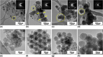
To further understand the crystallization of 3DOm-i zeolites through MHT treatments, the growth development of 35 nm 3DOm-i BEA zeolites after each hydrothermal treatment cycle was monitored by TEM and SEM as shown in Fig. 7 and S1. The microscopy results revealed a continuous growth of 3DOm-i BEA zeolite particles stacked and concatenated by spherical elements. The size of 3DOm-i BEA zeolite particles is determined by the number of spherical elements stacked together, while the size of spherical elements is determined by the center-to-center distance of two neighboring mesopores of the 3DOm carbon template.
TEM images of 3DOm carbon/zeolite composites after (a) 1st cycle, (b) 2nd cycle, (c) 3rd cycle, (d) 4th cycle, and the high-magnification TEM images of 3DOm-i BEA zeolites after (e) 1st cycle, (f) 2nd cycle, (g) 3rd cycle, (h) 4th cycle (inset: electron diffraction patterns from the selected areas).

After the first MHT cycle (100 °C, 4 days), discrete zeolite particles with average diameters less than 200 nm were formed inside the 3DOm carbon [Figs. 7(a) and S1(a)]. These particles consisted of dozens of 35 nm spherical elements with rough surfaces [Fig. 7(e)], which might have arisen from the low crystallinity of the formed BEA zeolite in this stage. When the synthesis proceeded to the second MHT cycle, the BEA zeolite crystals propagated from cage to cage of 3DOm carbon and the size of the discrete particles increased to 100–300 nm [Fig. S1(b)]. Moreover, some adjacent zeolite particles were concatenated together, which could be due to the limited growth space within the carbon template [see the yellow arrows in Fig. 7(b)]. The rough surfaces of the spherical elements were also observed in this stage [Fig. 7(f)], which means an incomplete filling of the spherical cavities of the 3DOm carbon just as the first MHT cycle.
In comparison with the second MHT cycle, the diameter of 3DOm-i BEA particles after the third cycle increased to 200–500 nm [Fig. 7(c) and S1(c)]. Besides propagating from cage to cage, the zeolite spherical elements gradually filled up every seeded cages of the 3DOm carbon, showing up smooth surfaces observed by TEM [Fig. 7(g)]. After the fourth MHT cycle, nearly 80% cages of the 3DOm carbon were occupied by the zeolite spherical elements with smooth surfaces [Figs. 7(d) and 7(h)] and a monolithic morphology was observed after the removal of carbon replica by calcination [Fig. S1(d)].
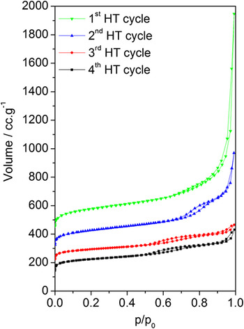
Besides the imprinted structure, the ordered mesoporosity of 3DOm-i BEA zeolites was also evolved from the MHT treatments. Figure 8 shows the nitrogen adsorption isotherms of 3DOm-i BEA zeolites after each MHT cycle. Before the nitrogen adsorption experiments, all the samples were calcined for the removal of carbon templates and organic structure-directing agents.
Nitrogen adsorption-desorption isotherms of 3DOm-i BEA zeolites after every hydrothermal treatment cycle. Carbon templates and organic structure-directing agents were removed by calcination before measurements.

After the first MHT cycle, no obvious hysteresis but a leap at high relative pressure (P/P 0 > 0.9) was observed in the nitrogen adsorption isotherm, indicating a very small particle size of 3DOm-i BEA zeolites with limited mesoporous structures. After the hydrothermal treatment processed to the second cycle, a clear hysteresis appeared in the nitrogen adsorption isotherm, which demonstrated the presence of ordered mesoporosity profited from the increase of the particle size. In comparison with the second MHT cycle, the hysteresis in the nitrogen adsorption isotherms of the 3DOm-i BEA zeolites after the third and fourth MHT cycles was shifted to the relative lower P/P 0, indicating a decrease in the mesopore size as a result of more adequate filling of the cavities of 3DOm carbon. BJH pore size analysis calculated from the adsorption isotherms of 3DOm-i BEA zeolites after every MHT cycles further demonstrated the mesoporosity evolution of 3DOm-i BEA zeolites during MHT synthesis (Fig. S2). Textural analysis (Table S3) of 3DOm-i BEA zeolites revealed a gradual increase in micropore volumes with MHT cycles, which was due to the increasing crystallinity, and the micropore volume of the 3DOm-i BEA zeolite after four hydrothermal synthesis cycles was almost the same as that of conventional BEA zeolites.
E. Si/Al ratio adjusting of 3DOm-i BEA zeolites through MHT method
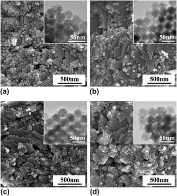
Under the appropriate hydrothermal conditions, 3DOm-i BEA zeolites with variation of Si/Al ratios can be synthesized through the MHT method by adjusting the compositions of the nutrient solutions. The microscopy images (Fig. 9) of 35 nm 3DOm-i BEA zeolites with Si/Al ratios of 14, 22, 24, and 27, respectively, determined by ICP chemical analysis, revealed a high utilization of carbon templates leading to a rough monolithic morphology with stacking and concatenation of zeolite spherical elements. Wide-angle [Fig. S3(a)] and small-angle [Fig. S3(b)] XRD patterns showed the signature reflections of BEA zeolites and ordered mesoporous structures, respectively. The mesoporosities of 3DOm-i BEA zeolites with various Si/Al ratios were further confirmed by nitrogen adsorption–desorption isotherms as shown in Fig. S4(a). Besides the similar hysteresis coming from the ordered mesoporous structures replicated from 3DOm carbon (0.5 < P/P 0 < 0.8), the isotherms of 3DOm-i BEA zeolites with relative lower Al contents exhibited a second hysteresis corresponding to a mesopore of ∼30 nm, revealed by BJH pore size distribution calculated from the adsorption isotherms [as shown in Fig. S4(b)]. Textural analysis (Table S4) indicated that the micropore volumes of 3DOm-i BEA zeolites with various Si/Al ratios were similar to those of conventional BEA zeolites. The results suggested that 3DOm-i BEA zeolites with variation of the Si/Al ratio ranging from 14 to 27 can be synthesized within 3DOm carbon by MHT treatments.
SEM images of 35 nm 3DOm-i BEA zeolites with Si/Al ratio of (a) 14, (b) 22, (c) 24, and (d) 27 (inset: high-magnification TEM images).

IV. CONCLUSIONS
In summary, confined synthesis of 3DOm-i zeolites was achieved by MHT and SAC methods. 3DOm-i BEA and 3DOm-i MFI zeolites were synthesized by the MHT method, while 3DOm-i Al-ZSM-5 zeolite was synthesized by the SAC method. A thorough comparison of the structures between silica colloidal crystals and the corresponding replicated 3DOm-i zeolites suggested an imperfect replication happened in the confined growth, and shape, size, and also mesopore morphology deviations existed in the replication process, which was synthetically caused by the structure sintering at the particle–particle interfaces of silica colloidal crystals and the imperfect filling of cages of the 3DOm carbon template. Moreover, the resulting structure of 3DOm-i zeolite was not related to the synthesis method (MHT or SAC), but depended on the type of the synthesized zeolite. The growth development of 3DOm-i BEA zeolites through the MHT method confirmed that the crystallization took place in the 3DOm carbon template by a cage-to-cage propagation growth process. The Si/Al ratio of 3DOm-i BEA zeolites was controlled from 14 to 27 by MHT treatments with tuning the amount of Al in the initial precursor solutions and optimizing the synthesis conditions. It is reasonable to expect that the investigation demonstrated here will be significant to understand the confined synthesis process and contribute to the fabrication of new hierarchical porous materials.
ACKNOWLEDGMENTS
H. Chen and P. S. Lee contribute equally to this work. H. Chen is grateful to China Scholarship Council (CSC, 2009615071) for a fellowship, to Prof. M. Tsapatsis for hosting him as a joint-training student studying in University of Minnesota, and also to Natural Science Foundation of Northwest University (No.: NG 13026, PR 12108) for supporting his work. Dr. Wei Fan in University of Massachusetts-Amherst is greatly thanked for his direction and modification of the manuscript.