I. INTRODUCTION
The important demand of power amplifiers (PAs) with high performances and a low cost requires the development of more and more compact chips [Reference Lin1–Reference Bessemoulin, Suh, Richardson, Mahon and Harvey3]. To increase the compactness of these amplifiers, one solution consists in decreasing the size of its unitary cell, while increasing their gain and improving their shape factor defined as the ratio between the vertical size and the horizontal size. A shape factor close to one would reduce the total vertical size of the PA and therefore would minimize its total area. To reach this objective, a new topology of elementary power cells in monolithic microwave integrated circuit (MMIC) technology must be designed. The keypoint of this design is to provide the same power performances than a single transistor with the same gate width and a shape factor of one. A new cell based on cascode theory appears to be a good candidate for this task.
II. MMIC TECHNOLOGY
The new cell reported in this paper is used for Ku band PA. It has been designed with a 0.25 µm GaAs pseudomorphic high electron mobility transistors (PHEMT) [4]. The MMIC fabrication is based on a double recess power PHEMT process, using 0.25 µm aluminum T-gates. The MMIC has been realized on 70 µm substrate, 30 Ω/□ TaN thin film resistor, 250 pF/mm2 MIM capacitors, air bridges, and 20 µm via holes. A 1.2 mm gate width transistor, with small via holes under each source is used to design this cell, thus ensuring a high gain and good thermal stability.
III. POWER CELL MMIC DESIGN
A) Cascode cell topology
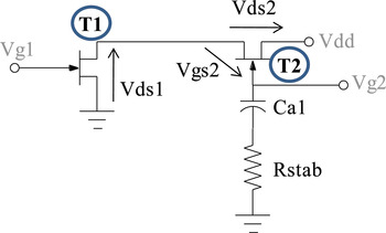
Various amplifiers with cascode cells have been proposed in the literature mainly in order to obtain either a wide band [Reference Martin5–Reference Darwish, Hung, Viveiros and Kao7] or a high gain at very high frequencies, especially for GaN HEMT technology [Reference Dennler, van Raay, Seelmann-Eggebert, Quay and Ambacher8]. However, no attempts have been made with integrated stability resistance and capacities between gate fingers. This new topology allows us to decrease the shape factor of the transistors while maintaining the advantages of the cascode configuration. This new cell is made of two transistors in cascade as shown in Fig. 1.
Cascode cell topology schematic.

The first one is in a common source configuration. Its drain is connected to the source of the second transistor which is in a common gate configuration. The goal of this topology is to add the drain voltages of each transistor which are both conducting the same drain current. Therefore, the output power and the gain of a cascode cell are twice bigger than for a single transistor. Other advantages of this cell rely also on the ability of doubling the drain bias voltage, which leads to a higher output impedance and to a better input/output isolation. In order to add the drain source voltages of the transistors some care must be taken to adapt the levels of voltage applied to the gate of transistor (T2). Indeed, in large signal, V ds1 voltage is applied directly to the gate of transistor in common gate configuration (T2). Without any precaution this transistor would be quickly saturated and destroyed. Therefore, a capacitance (C a1) is added in series with the gate as shown in Fig. 1. This capacitance (C a1) and the input capacitance C gs2 act as a frequency independent voltage divider between V ds1 and V ds2. The second transistor is biased through a 1000 Ω resistance. The cascode cell being sensitive to oscillations, a resistance R stab is added in series with C a1 capacitance to limit all instability phenomena. Both values of C a1 and R stab have been optimized in order to propose a trade-off between power performances and stability.
B) Integrated cascode layout
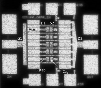
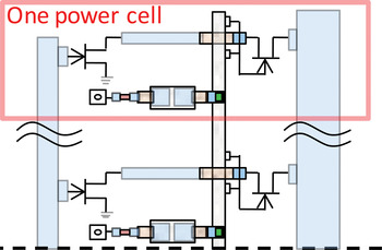
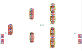
The layout of the compact cell is shown in Fig. 2.
Cascode cell layout.

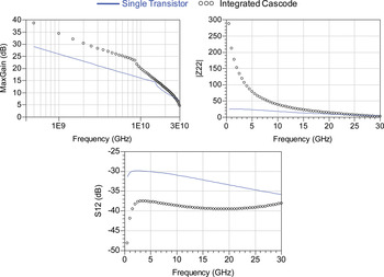
Drains of common source transistors are also sources of common gate transistors, thanks to the micro-strip line which crosses the gate bus through the air bridges. This provides an integrated aspect to the cascode cell. Thanks to via holes in sources of the first transistor, both C a1 capacitance and R stab resistance are distributed between each two gate finger pairs. This configuration ensures a perfect symmetry in the topology of the power cell. The number of elementary cells of two gate fingers can be adjusted to the total power required. As mentioned previously, the vertical size is 413 µm whereas that of a single transistor with the same gate width is 790 µm leading to an improvement of 48% and a shape factor which is close to one. Figure 3 shows that the integrated cascode exhibits a higher linear gain, a better output impedance, and a better input/output isolation than a single transistor with the same gate width.
Comparison of S 12, Z 22, and maximum available gain between an integrated cascode cell and a single transistor with the same gate width.

IV. MODELING AND REALIZATION
A) Distributed approach
The cascode design has been performed through a distributed approach. Firstly, we have extracted intrinsic and extrinsic circuit parameters of a 12 × 125 µm transistor. As the transistor model is scalable we have replaced the 12 × 125 µm transistor by six transistors of two gate fingers and we have compared this simulation with 12 × 125 µm transistor measurements. Gate and drain buses are simulated with the electromagnetic software ADS-momentum. We have adjusted the two gate fingers transistor model in order to have a good agreement between this model and measurements. Results are illustrated in Figs 4 and 5.
[S] parameters measurements of 12 × 125 µm transistor compared with its distributed model composed of six transistors of two gate fingers.

Load pull measurements of 12 × 125 µm transistor with its distributed model @ 12 GHz for Z load = 13.3 + j17.4 Ω.

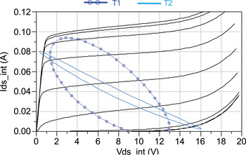
In the integrated cascode, the scalable model of transistor with 12 gate fingers of 100 µm width has been replaced by six transistors of two gate fingers with the same width. Figure 6 shows integrated cascode modeling. Passive elements havebeen simulated with ADS-momentum [Reference Larique9]. Both C a1 and R stab values have been optimized in order to obtain good power performances and to ensure stability of cascode cell. The total values found are C a1 = 525 fF and R stab = 3 Ω which are distributed in five elementary cells with R stab = 15 Ω and C a1 = 105 fF. In order to validate the power optimization of the cascode cell, Fig. 7 shows the simulated intrinsic load lines for both transistors T1 and T2 at 12 GHz in the same load conditions as those used for the load pull power measurements presented in the next section (i.e. Z load = 16.5 + j20.2 Ω). We can observe the excellent optimization for T2. However, T1 remains not fully optimized. Some approaches such as “self-biased optimization” technique [Reference Sowlati and Leenaerts10] have been tried, without convincing results. A trade-off between the power optimization and the shape factor has been applied to obtain the topology shown in Fig. 2.
Distributed model of integrated cascode.

Load cycles of each transistor.

B) Stability analysis
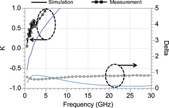
Owing to a high gain, the cascode cell is sensitive to oscillations. That is why the linear stability analysis must be performed [Reference Suarez11]. Figure 8 shows the Rollet factor K and the determinant delta of S matrix. K exhibits that the cascode cell is unconditionally stable between 8 and 30 GHz. We can conclude that the cascode cell is stable for all loads in the Ku band. However, this study reveals that cascode cell is conditionally stable from 0 to 8 GHz. Therefore, the stability circles from 0 to 40 GHz have been examined. For low frequencies (between 0.5 and 2 GHz), we observe a risk of oscillations. Some precautions with additional capacitances have been taken during measurements to avoid all instability phenomena. During this phase, no oscillation appeared.
Rollet factor and delta of [S] parameters matrix.

C) Thermal stability analysis
The cascode cell presents good power performances if both transistors are biased with the same voltage. As the two output current sources of transistors (T1) and (T2) are in series, we could suspect that the bias voltages V ds1 and V ds2 are proneto variation due to the temperature increase. This can lead to an over bias of one of the transistors. In fact, as T2 is driven by the current of T1, this current imposes the value of the gate/source voltage of T2 maintaining T2 in its saturation region. Therefore, V ds1 = V g2 − V gs2 = V dd − V ds2 and the voltage equilibrium between T1 and T2 is ensured by a correct choice of the T2 gate bias. This ensures thermal stability of the cascode. This has been confirmed through the use of an electro-thermal model specially developed for that study. A 3D thermal simulation revealing a poor coupling (Rth 12) between T1 and T2 has been performed in ANSYS. The self thermal resistance of T1 (Rth 1) is 10 % lower than T2 (Rth 2) due to small via holes in sources that are not present in T2. The thermal model is illustrated in Fig. 9
Thermal model including self heating and coupling effects.

V. MEASUREMENTS AND RESULTS
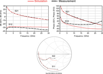
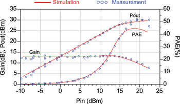
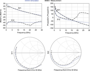
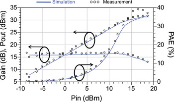
The on chip measurements of small signal gain and input/output return losses of the designed PHEMT integrated cascode cell are shown in Fig. 10. We can observe a good agreement between measurements and the distributed model. The model has beenvalidated with load pull power sweep at 12 GHz for the optimum load impedance, Z load = 16.5 + j20.2 Ω (Fig. 11).
Measured and distributed model [S] parameters of a cascode cell in the 0.5 to 30 GHz range (V dd = 16 V, Ids = 160 mA)

Measured and modeled power sweep of cascode cell at 12 GHz (V dd = 16 V, Ids = 160 mA)

VI. INTEGRATED CASCODE PHEMT PA MMIC
A) MMIC amplifier design
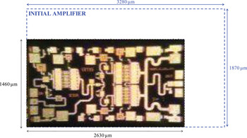
Using the integrated cascode, a 2W PA for Ku band has been designed. Figure 12 shows a photography of the MMIC Ku-Band amplifier. If we compare this new design to the Ku-Band amplifier, called “initial amplifier” (Fig. 13), developed by united monolithic semiconductors (UMS) [12], we can clearly see that only two output cells have been used in order to achieve the output power expected instead of four transistors for the initial amplifier. We have seen in the previous section that the integrated cascode cell vertical size has been reduced by 48% compared to a single transistor with the same gate width. Moreover, the shape factor is close to 1 whereas for a single transistor, it is close to 4. So, the vertical size of the amplifier will be decreased. The transistor type of the other stages and the stages number are very important to realize a compact amplifier. As the linear gain of integrated cascode is twice higher than a single transistor, we have chosen to take only two stages to provide the linear expected gain. This is performed with one cascode cell in the first stage to drive the second stage to deliver the linear gain of 24 dB. As the stage number decreases like the number of cell in each stage, the amplifier area has reduced by 40% compared to the initial amplifier with the same performances. The amplifier design is easier and faster thanks to this simplification.
2W amplifier layout.

2W initial amplifier.

In order to design this compact amplifier, we have used the distributed model of the integrated cascode. Moreover, all passives parts for the output match, the inter-stage and the input stage have been simulated with momentum to take into account all electromagnetic couplings.
Since the cascode cell is sensitive to oscillations, a first step to verify that the amplifier is stable consists of checking the variation of output and input impedances of each cascode cell for all stages. No problem has been observed. We have also takena particular care in order to ensure stability. First of all, Resistance and Capacitance (RC) filters have been added to the cascode cell input, close to the gate bias circuit to cancel oscillations at harmonics of fundamental frequency. They also help us to match the input stage and inter-stage. Balanced resistances in series between the two gate buses of each cascode cell have been included in the last stage. They avoid internal loops between each cell. Low-frequency oscillations are removed by a resistance in series with a capacitance connected to the ground on the drain bias. Finally, we have included resistance bridges in the gate bias circuit of the common source transistor of cascode cell. These bridges increase the gate voltage bias in order to decrease the sensitivity of cascode cell to this voltage. A complete study of stability, linear and nonlinear, has been performed. The conclusion is that no oscillation appeared [Reference Dechansiaud13].
B) MMIC amplifier characterizations
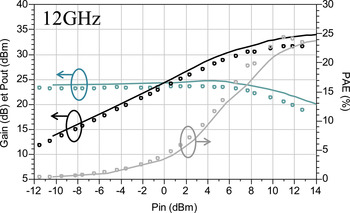
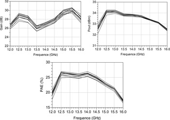
First, we have performed continuous wave (CW) power measurements on board from 10 to 18 GHz in order to check the amplifier model. Figure 14 shows the measured and simulated power characteristics at 12 GHz. We can consider that we have a fairly good correlation between measurements and simulations in order to estimate the power behaviour of this device. Pulsed power measurements on wafer have also been realized from 12 to 16 GHz to show the power performances without thermal effects (Fig. 15). The pulse length is equal to 25 µs and the duty cycle is taken to 10%. This cascode amplifier delivers 33.6 dBm of output power, with 25% of Power Added Efficiency (PAE), a linear gain of 28 dB and −10 dB of return losses from 12.5 to 15.5 GHz for the bias point at Vds 1ststage = 16 V, Vds 2ndstage = 16 V and Ids = 490 mA. We recall that the old version provides 34 dBm of output power, 29 dB of linear gain and 25% of PAE for the same bias point and the same frequency range. The main advantage of this amplifier is the decrease of 40% of the area compared with the oldest version.
CW measured and distributed power characteristics of the amplifier at 12 GHz (V dd = 16 V, Ids = 490 mA).

Pulsed measured power performances, output power, linear gain, and PAE from 12 to 16 GHz (V dd = 16 V, Ids = 490 mA).

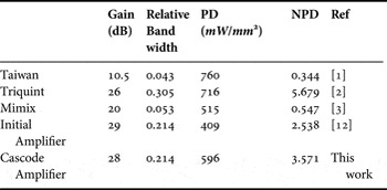
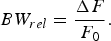
Table 1 shows the comparison in terms of performances between the amplifier with integrated cascode cells and the state of the art. In this design various characteristics are important. Indeed, the amplifier must deliver a linear gain of 24 dB to avoid the use of driver at the input that would increase the cost. Moreover, it must work from 12.5 to 15.5 GHz and provide 33.5 dBm of output power. Its area must be compact enough to be competitive. In order to take into account all characteristics in the comparison we have defined a normalized power density (NPD) expressed by equation (1). BW rel corresponds to the relative band width (see equation (2)), where ΔF is the band width and F 0 the central frequency of the amplifier. PD is the power density.
 $$NPD = Gain\lpar dB\rpar\cdot BW_{rel} \cdot PD\comma \;$$
 $$BW_{rel} = \displaystyle{{\Delta F} \over {F_0 }}.$$
Comparison with the state of the art.

VII. CONCLUSION
This paper has reported the design modeling of a new integrated cascode cell. This new cell is more compact than a single transistor with the same gate width and exhibits the same power performances. The very good agreement between simulation results and measured data show the accuracy of the nonlinear model and also the efficiency of the design approach. Thanks to these promising results, a Ku-band compact amplifier has been designed. Measurement results are close to the initial amplifier. This main improvement is its area reduction of 40% which leads to an increase of its power density which is equal to 596 mW/mm 2 (409 mW/mm 2 for the initial amplifier).
ACKNOWLEDGEMENTS
Authors acknowledge UMS foundry for providing data and transistor samples and ESA for supporting this job.
 Adeline Déchansiaud received a M.S. degree in 2008 from the University of Limoges, and the PhD degree at XLIM laboratory (Limoges University, Brive) in June 2012. Her PhD deals with the modeling, the characterization and the design of an integrated cascode cell to reduce the area of Ku-band amplifiers. She joined NXP in July 2012 as a Design Engineer on the RF power business line. She is involved in characterization/design of MMIC amplifiers for base station applications.
 Raphaël Sommet received the French aggregation in applied physics in 1991 and a Ph.D. degree from the University of Limoges in 1996. Since 1997, he is a permanent researcher for the CNRS (French National Research Center) at XLIM labs in the C2S2 team “Nonlinear Microwave Circuits and Subsystems”. His research interests concern HBT device simulation, 3D thermal finite element simulation, model order reduction, microwave circuit simulation, and generally the coupling of all physics-based simulation with circuit simulation.
 Tibault Reveyrand (M'07) received the Ph.D. degree from the University of Limoges, France, in 2002. From 2002 to 2004, he was a Post-Doctoral Scientist with CNES (French Space Agency). In 2005, he became a CNRS engineer at XLIM. His research interests include the characterization and modeling of RF and microwave nonlinear components and devices. Dr Reveyrand was the recipient of the 2002 European GaAs Best Paper Award and is a member of the IEEE MTT-11 “Microwave Measurements” Technical Committee.
 Diane Bouw received the M.S. degree in microwave and optic communications in engineering from the Research Institute of Microwave and Optical Communications from the University of Limoges (IRCOM, Limoges, France), in 2005. She joined UMS in 2005 as a Design Engineer of MMIC components, where she worked on high power amplifier and nonlinear stability for several applications. Since 2009, she is an Advanced Product Designer Engineer on the High Power Transistor business Line and participates to the development of the Hybrid product based on GaN components for High power.
 Christophe Chang received the M.S. degrees in electronic from Pierre et Marie Curie University, Paris (France), in 2000 and PhD in electronics at University of Limoges (France) in 2004. In 2006, he joined United Monolithic Semiconductors (Orsay, France) where he is involved in development of the AsGa power technologies and responsible for the modeling task. From the last 2 years, he is involved with the characterization and modeling activities of the AlGaN/GaN technology for X-band applications.
 Marc Camiade received the Dpl. Eng. degree in physics and electronic engineering from the Institut National des Sciences Appliquées, Toulouse, France, in 1981. He joined Thomson-CSF in 1982 as a Design Engineer of hybrid circuits where he participated in a variety of microwave and millimeter-wave circuits. Since 1988, he has been Application Group Manager in charge of new product development based on MIC and MMIC components. He joined United Monolithic Semiconductors in 1996, in charge of the development of MMIC components for Defense, Automotive and Telecommunication applications. Since 2009, he is in charge of all the UMS advanced developments on new millimeter-waves and high power technologies. He is also responsible of the new Business Line “GaN Power Transistors”.
 Francois Deborgies graduated from Ecole Supérieure d'Electricité, France, in 1984 and received the M.Sc. in microwaves and modern optics from University College London, U.K., in 1985. In 1986, he joined the Central Research Laboratory (LCR) of Thomson-CSF (now Thales) in Corbeville, France. Within the Optical Link Laboratory, he has worked in the field of microwave photonics, and more specifically on high-frequency optoelectronic components and high-performance microwave optical links. He was responsible for the characterization of multi-gigahertz optoelectronics components and has also been involved in the design and realization of systems based on high-speed optoelectronics. In 1998, he became Head of the Microwave Modules Laboratory, which was concentrating on innovative packaging technologies up to millimetre-wave frequencies. In 2001, he joined the European Space Agency (ESA). Since then, he has been the Head of the Microwave and Millimetre-wave Section within the RF Payload Systems Division of the European Space Research and Technology Centre (ESTEC), Noordwijk, The Netherlands. His current topics of interest are as varied as MMICs, SAW devices, MEMS, and microwave packaging,… François Deborgies holds several patents.
 Raymond Quéré (M88-SM99) received the electrical engineering degree and French aggregation degree in physics from ENSEEIHT-Toulouse, Toulouse, France, in 1976 and 1978, respectively, and Ph.D. degree in electrical engineering from the University of Limoges, Brive, France in 1989. In 1992, he became a Full Professor with the University of Limoges, where he currently heads the research group on high-frequency nonlinear circuits and systems with the Institut XLIM of the Centre national de la Recherche Scientifique (CNRS), Brive, France. He is mainly involved in nonlinear stability analysis of microwave circuits. Dr Quéré is a member of Technical Program Comitee (TPC) for several conferences such as the European GaAs Conference. He was the chairman of European Microwave Week, Paris, France, 2005. He is a reviewer for numerous IEEE Transactions.