I. INTRODUCTION
Due to its unique structures and properties, carbon has generated excitement among materials scientists and engineers for many decades, from the synthesis of diamondReference Hall1, Reference Werner and Locher2 to Buckminster fullerenesReference Kroto, Heath, O’Brien, Curl and Smalley3 and carbon nanotubes (CNTs).Reference Iijima4 Recently, graphene has been added to this list due to very unusual properties such as charge mobility, band structure, and mechanical strength. This was emphasized by the Nobel Prize in Physics in 2010 “for groundbreaking experiments regarding the two-dimensional material graphene” awarded to Andre Geim and Konstantin Novoselov.5, Reference Novoselov, Geim, Morozov, Jiang, Zhang, Dubonos, Grigorieva and Firsov6 Numerous articles have been published on the synthesis and properties of graphene (for three recent reviews see Refs. Reference Wu, Yu and Shen7–Reference Wei and Liu9). There have also been earlier reports on graphitic platelets deposited after CNT deposition in a two-step process.Reference Trasobares, Ewels, Birrell, Stephan, Wei, Carlisle, Miller, Keblinski and Ajayan10, Reference Yu, Lu, Bo, Mao and Chen11 The present authors recently reported on the enhanced electrochemical double-layer performance of graphenated CNTs with varying foliate density, demonstrating the potential application of this hybrid structure.Reference Stoner, Raut, Brown, Parker and Glass12 Furthermore, recent reviewsReference Wu, Yu and Shen7–Reference Wei and Liu9 have also described vertically oriented graphene nanosheet structures but have not discussed the integration of graphene or graphitic nanosheets with CNTs.
The fundamental advantage of a combined CNT-foliate structure is the high surface area framework of the CNTs coupled with the high edge density of the graphene sheets. Graphene edges provide high charge density and reactivity, but they are difficult to arrange in a three-dimensional (3D), high-density geometry. CNTs are readily aligned in a high-density geometry (i.e., a vertically aligned forest) but lack high charge density surfaces—the sidewalls of the CNTs are similar to the basal plane of graphene. For example, the capacitance expected for the edge planes of graphene versus the basal plane is 3 versus 50 to 70 μF/cm2.Reference Randin and Yeager13 Combining these properties by growing protrusions or graphitic foliates from CNT sidewalls can provide a unique and valuable 3D nanoarray of graphene edges. Since the thickness of the foliate structures can vary from <10 to >20 layers in the present study, we will refer to these hybrid structures more generally as “graphenated CNTs” (g-CNTs) and the foliate structures as “graphitic foliates” or just “foliates”. They can be considered a foliated CNT because they are reminiscent of a striated, leaflike structure growing from a CNT stem or a foliated column in gothic architecture.
Many applications require high charge density materials at the nano- or microscale, such as electrical conductors for nanoscale solid state devices, and therefore would benefit from high charge densities at edges. Examples of applications that could benefit from the combined structure include (i) an electrochemical double layer capacitor or “supercapacitor,”Reference Raut, Parker and Glass14 (ii) a neural stimulation electrode,Reference Cogan15 and (iii) a field emission electron source.Reference Natarajan, Gilchrist, Piascik, Parker, Glass and Stoner16 These g-CNT structures may also be advantageous in CNT–polymer composites,Reference Kurt, Karimi and Hoffmann17, Reference Lourie and Wagner18 providing protrusions to enable mechanical interlocking between the CNTs and the matrix as well as reactive sites along the length of the CNT for chemical binding to the polymer matrix. One of the problems reported for composites that use CNTs as the reinforcing phase is stress transfer from the matrix to the CNT. The edge structure of graphitic foliates can enable a controllable level of chemical interaction with the matrix and the flat surfaces of the foliates, forming an interlocking structure that mechanically transfers the load.
Kurt et al.Reference Kurt, Karimi and Hoffmann17, Reference Kurt and Karimi19, Reference Kurt, Klinke, Bonard, Kern and Karimi20 have grown “decorated C:N Nanotubes” using hot filament growth of surface decorations on CNTs, resulting in structures with some similarities to those presented here. The structures were described as “disordered multi-walled nano-tubes” that were “probably hollow” and the graphitic decorations were described as “lamellar needle-like structure with a preferential radial growth direction (perpendicular to the tube axis).”Reference Kurt and Karimi19 Mata et al.Reference Mata, Ferro, Fernandes, Amaral, Oliveira, Costa and Silva21 have also reported what appear to be graphitic nanosheets integrated with CNTs in the context of a study on the nucleation of carbon nanostructures on nickel foil. Although there is little discussion on the details of the structure, Mata et al. identified the core structures as carbon nanofibers rather than CNTs.
The present research reports the growth and characterization of g-CNTs—a nanostructure that has the potential to integrate the exceptional properties of graphene or graphitic nanosheets with those of CNTs by growing the nanosheets or foliates protruding from the sidewalls of the CNTs. A proposed mechanism for foliate formation during CNT growth is also presented.
II. EXPERIMENTAL
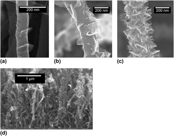
g-CNTs were grown using a 915 MHz microwave plasma enhanced chemical vapor deposition (MPECVD) system. To prepare the substrates, 5-nm iron films were deposited on Silicon(100) wafers using a CHA electron-beam evaporation system. Prior to growth, the coated substrates were heated to 1050 °C in 150 sccm of NH3, followed by striking and stabilizing a plasma at 21 Torr and 2.1 kW of magnetron input power. The pressure of 21 Torr was maintained throughout the pretreatment and growth steps. Substrates were then pretreated for 180 s in the plasma. Following pretreatment, growth of the g-CNTs was accomplished by changing the gas flow to 150 sccm CH4 and 50 sccm NH3 for 360 s. Details of the deposition system can be found in Cui et al.Reference Cui, Zhou and Stoner22 Scanning electron microscopy (SEM) images of these nanostructures can be seen in Fig. 1. Through adjustments in growth conditions, the density of the graphitic features can vary from none (i.e., only CNTs grow), low density [Fig. 1(a)], medium density [Fig. 1(b)], to high density [Fig. 1(c)]. Increasing density is accomplished by a combination of higher growth temperature, higher methane to ammonia ratio, and/or longer growth time, as described in more detail later. The specific capacitance was measured using electrochemical impedance spectroscopy (EIS) between 0.1 Hz and 100 kHz using a 1252 frequency response analyzer and 1287 electrochemical interface (Solartron Analytical, Farnborough, Hampshire, UK) with a Ag–AgCl reference electrode in water with model interstitial fluid (2 mM Na2HPO4·7H2O, 0.5 mM NaH2PO4·H2O, 28 mM NaHCO3, 7.5 mM KHCO3, 110 mM NaCl, 0.5 mM MgSO4, 0.5 mM MgCl2, and 0.5 mM CaCl2) purged with 5% O2, 6% CO2, and 89% N2 was used for all measurements. Raman spectroscopy was performed with a Horiba Jobin Yvon LabRam ARAMIS system (Horiba, Kyoto, Japan) that was calibrated using a silicon standard before use. SEM was performed using a FEI XL30 SEM-FEG (FEI, Hillsboro, OR) and transmission electron microscopy (TEM) was performed with a FEI Tecnai G2 Twin with an accelerating voltage of 200 kV.
Scanning electron microscopy (SEM) images of graphenated carbon nanotubes (g-CNTs). (a) Low-density graphene foliates on a CNT. (b) Medium-density graphene foliates on a CNT. (c) High-density graphene foliates on a CNT. Structures were reproducible and observed over several square centimeters after microwave plasma chemical vapor deposition growth. (d) Cross-sectional SEM image showing a typical aligned g-CNT film.

III. RESULTS AND DISCUSSION
g-CNTs consist of perpendicularly oriented foliates growing out from the sidewalls of multiwall CNTs. Figures 1(a)–1(c) show three different densities of foliates. Figure 1(d) depicts an SEM cross section of a typical film of semialigned CNTs with foliates along their length. The density of foliates can be controlled by varying the growth conditions. In Figs. 1(a)–1(c), the foliate density per micron of CNT length increases from 4.2 to 5.3 to >15.0, respectively.
TEM images of the g-CNTs (Fig. 2) provide additional insight into the nucleation and growth of the foliated structures. The hollow core, characteristic of CNTs,Reference Endo, Takeuchi, Hiraoka, Furuta, Kasai, Sun, Kiang and Dresselhaus23 is clearly observed in Fig. 2(a). The CNT sidewalls, however, are unusually thick relative to the diameter, a consistent characteristic for the g-CNTs observed in this work. What appears to be secondary nucleation is also observed in Fig. 2(b); smaller foliates protruding from the primary “leaf” itself growing normal to the CNT sidewall. The specific mechanism for secondary nucleation is currently unknown and will be the topic of future studies but defects at the active growth surface of the foliate are expected to play a role.Reference Zhu, Wang, Holloway, Outlaw, Zhao, Hou, Shutthanandan and Manos24 The majority of the foliates grow with a curvature vector that is coplanar with the axis of CNT growth, i.e., the curvature being either concave up or concave down, suggesting that the fiber texture of the foliate may have nucleated from the original fiber texture of a fractured CNT. TEM also indicated that both coherent and incoherent boundaries existed between the CNT sidewalls and the foliates [Figs. 2(c) and 2(d)], respectively, where the coherent boundaries tended to be associated with smaller foliates. Theories of interface development in nucleation and growth of a new phase can provide some insights about the CNT–foliate interface.Reference Porter and Easterling25 As a new phase nucleates on an existing surface, the interface between the two materials generally begins as a coherent boundary if the lattice mismatch is small. As growth of the new phase proceeds, interfacial dislocations tend to form to relieve the strain energy that builds at the interface due to mismatch of the lattices. When the nucleus reaches a critical size, the increase in volumetric elastic energy is greater than the interfacial energy and the interface becomes incoherent to relieve the elastic strain that has developed.Reference Porter and Easterling25 Similarly, in the present case, the lattice mismatch between the foliates and the CNT sidewalls would result in coherent interfaces for small foliates in the early stages of nucleation and growth and incoherent interfaces between larger foliates and the CNT sidewalls as has been observed by TEM. The coplanar alignment suggests that the graphene foliates may have nucleated from defects or fractures in the CNT sidewall. More on proposed mechanisms will be covered in Sec. IV, to follow.
Transmission electron microscopy images of g-CNTs. (a) The hollow core of the nanotube shows graphene foliates in CNTs, rather than nanofibers (b) Secondary nucleation of graphene foliates is indicated by arrows. The presence of secondary nucleation indicates an active growth surface on the graphene foliates. (c) Coherent interface between CNT sidewall and graphene foliates. Inset: lower magnification image of same. (d) Incoherent interface between nanotube sidewall and the graphene foliates. Inset: lower magnification image of same. (e) Lattice fringes from CNT stem and graphene foliate are visible. The average of 11 fringes for the CNT and leaf gives values of 0.362 nm in the foliate and 0.351 nm for the CNT. This is consistent with a range of 0.345 to 0.365 nm for CNTs.Reference Endo, Takeuchi, Hiraoka, Furuta, Kasai, Sun, Kiang and Dresselhaus23 (f) A foliate around 10 layers thick. As is typical for the foliates, it is thicker near the base where it is attached to the nanotube and gets thinner towards the edge.

Figure 2(c) shows a coherent interface, with the lattice fringes bending from the CNT sidewall to the foliate, suggesting a single continuous carbon layer can be part of both the CNT sidewall and the foliate. Figure 2(d) shows an incoherent interface, where the foliate appears to have a break in the lattice fringes between the CNT sidewall and the graphene layers. This could indicate a high angle twinReference Porter and Easterling25 or a grain boundary between the CNT sidewall and the foliate. Additional evaluation of the lattice fringes [Fig. 2(e)] indicates that the fringe spacing for the CNT and the foliate is consistent with graphene lattice spacing. The lattice fringes were 0.362 nm (average of 11 fringes) for the foliate versus 0.351 nm for the CNT (average of 11 fringes). The trend in the fringe spacing is consistent with previous work on the variation of the layer spacing of graphene sheets as a function of CNT diameter that found a smaller number of layers have a larger lattice spacing.Reference Endo, Takeuchi, Hiraoka, Furuta, Kasai, Sun, Kiang and Dresselhaus23, Reference Singh, Iyer and Giri26Fig. 2(f) shows a thin foliate with approximately 10 fringes at the base and narrowing to just a few fringes at the tip.
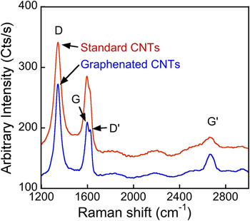
Raman spectroscopy was used to characterize the different bonding states present in the g-CNTs compared to standard CNTs. Although the peak designations for Raman spectra of CNTs and graphene are still debated (compare designations of the band at 2700 cm−1 in Ferrari et al.Reference Ferrari, Meyer, Scardaci, Casiraghi, Lazzeri, Mauri, Piscanec, Jiang, Novoselov, Roth and Geim27 and Faugeras et al.Reference Faugeras, Nerriere, Potemski, Mahmood, Dujardin, Berger and de Heer28), there is reasonable consensus about the primary peaks designations. For CNTs and graphene, these peaks are the D, D′, G, and G′. Their descriptions follow the review of Raman of CNTs and graphene by Dresselhaus et al.Reference Dresselhaus, Jorio, Hofmann, Dresselhaus and Saito29 Representative spectra from g-CNTs and standard CNTs are presented in Fig. 3, showing an increase in G′ to G ratio when the foliate structures are present on the CNTs. This increase suggests the presence of graphene on the foliated CNTs.
Standard CNTs are compared to g-CNTs. The expected increase for the ratio of G′ to G for the g-CNTs is observed. The spectra are smoothed to remove digitizer noise.

In summary, SEM, TEM, and Raman spectroscopy reveal several characteristics of the g-CNTs. First, the CNTs have hollow cores and straight sidewalls (Fig. 2). Second, the foliates grow out of the CNTs and are not simply attached by van der Waals bonding (Fig. 2). Third, the nanosheets have a fringe spacing that agrees with published values for graphene layer spacing, i.e., greater than 0.35 nm [Fig. 2(e)]. The thinnest foliates and tips of thicker foliates are graphene-like in their thickness (<10 layers), while the base of the thicker foliates are more graphitic, like the wall of the host CNT [Fig. 2(e)]. Fourth, Raman spectra of g-CNTs versus standard CNTs suggests, by changes in relative peak intensity, that there is a higher graphene component in the g-CNTs versus standard CNTs (Fig. 3).
IV. GROWTH MECHANISM
The growth process for the g-CNTs may provide a new avenue for understanding how these foliates grow or develops certain morphological characteristics. The following is a proposed nucleation and growth mechanism for the graphitic foliates formed during CNT growth. It is not conclusive, but attempts to be consistent with the structural observations and process responses reported above.
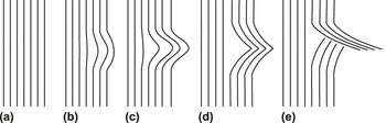
A schematic representation of the proposed CNT graphenation process is provided in Fig. 4. The model is as follows:
(i) The outer sidewalls of the CNTs grow at a higher rate than the inner walls, causing residual stress to build up in the outer walls;
FIG. 4.Schematic of the nanoscale buckling of a CNT and thus the creation of a nucleation site for foliated graphene to grow. Note that the sequence (a)–(d) is similar to that proposed by Thostenson and Chou for CNT buckling.Reference Thostenson and Chou40 (a) unbuckled CNT walls, where the left side is toward the center of the CNT and the right side is the exterior of the CNT. (b) Local bending of several graphene layers in the external walls of the CNT because of a growth rate differential. (c) Continued bending of walls. (d) Buckling of CNT walls. (e) Breaking of CNTs walls, leading to foliate nucleation site and strain relaxation of external CNT walls.

(ii) the residual stress eventually exceeds the strength of the CNT sidewalls, causing localized buckling;
(iii) the localized buckling creates a protrusion of a few layers of carbon from the sidewall preferentially in locations where sidewall defects exist:
(iv) the protrusion fractures and a nucleus of foliated graphene is formed;
(v) carbon continues to attach to the foliated graphene tip through gas-phase adsorption and surface diffusion, and the sidewall continues the protrusion process; and
(vi) larger CNT diameters allow increased foliate density due to higher defect densities and stress gradients.

Obtaining g-CNTs likely requires not only surface defects but also specific growth conditions that enhance edge growth. It is possible that the defects are present on standard CNTs, but these defects do not grow foliates due to unfavorable growth conditions. Several observations and literature reports support this model of foliate nucleation and growth as discussed below:
A. Decreasing strength and increasing defect density as CNT diameter increases
It has been reported that the Young’s modulus of CNTs decreases as the diameter of the CNT increases, particularly for multiwalled CNTs (MWCNTs).Reference Li, Wang and Lee30–Reference Lee, Lukic, Magrez, Seo, Briggs, Kulik and Forro33 Li et al.Reference Li, Wang and Lee30 derived an analytical result for the effect of diameter and found that it had a 1/x dependence, converging on the bulk value for the material . This led to a drop from 600 to 10 GPa as the diameter of the MWCNTs increased from 10 to 25 nm. The effect can be seen via in situ TEM measurements made by Poncharal et al.Reference Poncharal, Wang, Ugarte and de Heer34, where the greatest deformation occurs in the outer layers of a bent nanotube, gradually decreasing further into the nanotube. The primary cause of the decrease in Young’s modulus of larger diameter CNTs is the lower shear strength of the larger diameter graphene shells that comprise the CNT sidewalls.Reference Robertson, Brenner and Mintmire35, Reference Peng, Locascio, Zapol, Li, Mielke, Schatz and Espinosa36
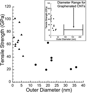
Defects also cause a lower tensile strength with increasing diameter in CNTs,Reference Lee, Lukic, Magrez, Seo, Briggs, Kulik and Forro33 generally following Young’s modulus (Fig. 5).Reference Yu, Lourie, Dyer, Moloni, Kelly and Ruoff32, Reference Wang, Golberg and Bando37 This effect was also found in CNT composites, but the interpretation is more difficult because of the presence of a copper matrix.Reference Sun and Chen31 Although the data contain significant scatter for any specific CNT diameter, the trend is clear—tensile strength decreases dramatically as CNT diameter increases. For a 1.3 nm nanotube, the tensile strength was 102 GPa,Reference Wang, Golberg and Bando37 and for a 36 nm nanotube, the tensile strength was 24 GPa. The smallest diameter CNTs exhibiting graphitic foliates in the present work was 80 nm, suggesting that the tensile strength of the g-CNTs would be below the 24 GPa reported in the previous work. The decrease in both yield strength and tensile strength of CNTs as diameter increases can be attributed to the increased defect density that occurs in larger diameter CNTs, as explained by the metastable-catalyst growth model.Reference Lee, Lukic, Magrez, Seo, Briggs, Kulik and Forro33 This supports the observations and proposed model in the present work. Graphitic foliates are unlikely to form on small diameter tubes, and the maximum density of foliates increases with increasing diameter. The decreased strength allows the deformation of the sidewalls to occur, and the increased defect density provides a higher density of protrusion sites from which the foliates can nucleate and grow. This is also consistent with the surface inhomogeneities observed in the CNT sidewalls in the present work [Fig. 1(b)]. In contrast, the CNTs grown by Trasobares et al.Reference Trasobares, Ewels, Birrell, Stephan, Wei, Carlisle, Miller, Keblinski and Ajayan10 have a much smaller diameter; however, the structures were grown in two steps. CNTs were grown in one step with thermal CVD and were then modified with microwave plasma-enhanced CVD to add the foliate structures. In the present work, the diameter of the CNTs may be more important for the growth due to the simultaneous growth of the CNTs and foliates.
Tensile strength as a function of outer CNT diameter, measured using an AFM. (▲) are single-walled CNTs from Wang et al.Reference Wang, Golberg and Bando37 (●) are multiwalled CNTs from Yu et al.Reference Yu, Lourie, Dyer, Moloni, Kelly and Ruoff32 Inset shows the same data set with the abscissa scaled to show the diameter range from the present work where g-CNTs are observed.

B. Increased buckling with increasing diameter and temperature
Buckling also occurs more easily in larger diameter CNTs because the strain energy in a CNT wall increases with increasing diameter. This lowers the activation energy necessary to form the primary defect that allows buckling in CNTs, the 5-7-7-5 (Stone–Wales) defect.Reference Nakayama38 Additionally, buckling of the outer layers of a multiwalled CNT is easier at higher temperatures, such as those utilized during growth, because the walls have a lower tensile strength as temperature increases.Reference Poncharal, Wang, Ugarte and de Heer34 This is consistent with the conditions under which the foliates are formed in the present work. Furthermore, stress transfer between graphene layers is poor because of the lack of covalent bonding.Reference Wei, Cho and Srivastava39 This is expected to lead to increased stress concentration at defects as the stress will not be transferred to adjacent walls. The stress concentration leads to buckling and then to a kink, according to the model proposed by Thostenson and Chou.Reference Thostenson and Chou40
The foliates created by this local buckling will be additive in number for CNTs of larger diameters. That is, the foliates from layer n will grow along with the continued growth of the CNT such that foliates from layers n + 1, n + 2, etc. will all be visible on the surface of the CNT sidewalls after growth. This is consistent with observations that foliates of differing protrusion lengths are observed as the foliate density increases and that foliate–CNT sidewall interfaces are observed via TEM well below the surface of the outer CNT sidewall.
C. Sidewall-foliate continuity
From the TEM of the foliate–CNT sidewall interface [Fig. 2(e)], it appears that foliates are a continuous extension of the sidewall; thus, they can be envisioned as an integral part of the sidewall prior to the protrusion process. Consistent with a buckling process, a smooth continuous bend is even observed in the atomic layers from the sidewalls to the graphene foliate.
D. Periodicity in the graphene foliates
The graphene foliates appear to occur periodically at low density, consistent with a localized buckling mechanism that relieves the strain buildup in the vicinity of the buckle.
E. Rapid growth of outer walls due to diffusion profiles
The higher linear growth rate of the outer walls in the proposed model is enabled by their access to rapidly diffusing carbon along the substrate and catalyst surface as compared to being diffusion-limited within the nanoparticle. This has been verified by carbon gradient calculations.Reference Ducati, Alexandrou, Chhowalla, Robertson and Amaratunga41
An alternative source of defects has been proposed by Trasobares et al.Reference Trasobares, Ewels, Birrell, Stephan, Wei, Carlisle, Miller, Keblinski and Ajayan10 In this model, hydrogen attacks the curved nanotube surface, leading to a defect where the next most likely site of attack is the next ring in one direction along the CNT length, producing an unzipping of the CNT. This defect mechanism could cause the nucleation site of the foliates. The “graphitic wings” observed in Trasobares et al.Reference Trasobares, Ewels, Birrell, Stephan, Wei, Carlisle, Miller, Keblinski and Ajayan10 are attributed entirely to this ripping. However, nucleation and growth appear to be a more likely process for the g-CNTs as the foliates observed cannot be explained by the rearrangement of material in the CNT sidewall.
A second alternative source of defects is nitrogen from the ammonia used in the processing of the g-CNTs. Kurt et al.Reference Kurt and Karimi19 noted that nitrogen gas introduced in the growth caused surface defects, to the point of causing an amorphization of the surface. This has not been observed to such a degree in the present work. Replacing ammonia with hydrogen in the growth process is recommended for future work to investigate the role of nitrogen in the production of g-CNTs.
The growth mechanism for foliates requires further investigation, but the proposed stress-induced localized buckling mechanism is believed to play a key role. Ultimately, the mechanism must explain not only the formation of the foliates but also the process space ranging from graphitic nanosheets (without CNTs), through g-CNTs, to standard CNTs. Exploring the process window for graphene foliate formation and the effect of foliate density on the properties of the hybrid carbon nanostructure will be the subject of future research.
V. APPLICATIONS FOR g-CNTs
g-CNTs should be interesting in several application areas, especially those that benefit from high surface area graphene edges. Carbon nanosheets on planar substrates do not utilize the third dimension (i.e., perpendicular to the substrate), limiting any improvement in surface area for applications such as electrochemical electrodes and catalyst supports, where high surface area is important. In addition, since only the outer CNT walls are involved in the foliate growth, the high electrical conductivity of the CNT stem is preserved. Finally, unlike planar structures, the graphenated CNT is a potential candidate for composites, from lightweight conductors to load-bearing structures. Problems reported for the bonding of CNTs to the matrix in these compositesReference Kurt, Karimi and Hoffmann17, Reference Lourie and Wagner18 can be overcome using the reactivity of graphene edges present in these structures. The protrusions can also act as mechanical interlocking nanostructures to decrease slippage during deformation.
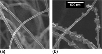
An application area of growing interest for carbon nanostructures in general is as electrochemical electrodes for either energy storageReference Chang and Hui-Ming42–Reference Obreja44 or neural stimulation.Reference Li, Andrews, Sakas and Simpson45–Reference Yeh, Chen, Su, Yew, Kao, Lee, Liu, Chen, Chang and Chang52 EIS was used to measure the specific capacitance of both g-CNTs and standard aligned CNTs. The CNTs were grown under identical conditions (1050 °C, 150 SCCM CH4:50 SCCM NH3), except for the growth time. The standard CNTs and g-CNTs were grown for 60 and 480 s, respectively, and are shown in Fig. 6. The capacitance at 1 Hz was determined using Zview2 software to fit measured impedance data to a series RLC circuit where circuit components are allowed to vary with frequency. The weight was quantified by direct measurement of the substrate before and after CNT growth. At 1 Hz, the weight-specific capacitance was 0.832 and 4.48 F/g for standard and g-CNTs, respectively, a 5.4× increase. Likewise, potential transient measurements (common in neural stimulating electrodesReference Cogan15) using symmetric, biphasic, and cathodic-first current pulses with 1 ms pulse width at 100-Hz pulse train frequency measured an area-specific capacitance of 143 and 1050 μF/cm2 for standard and g- CNTs, respectively, a 7.3× increase in capacitance per unit area. This result is consistent with the trend reported earlierReference Stoner, Raut, Brown, Parker and Glass12 and verifies the higher charge density inherent in the graphitic edges as compared to the basal plan associated with the CNT sidewall. A simple estimate of the degree of foliate coverage for a 4× improvement is approximately 20% of the sidewalls, which is in qualitative agreement with the foliate density shown in Fig. 6.
CNTs grown under the same conditions, but for different times. (a) Standard CNTs grown for 60 s. (b) g-CNTs grown for 480 s. The scale bar is common to both images.

VI. SUMMARY
g-CNTs have been grown with MPECVD. The graphitic foliates nucleate on the CNT surface during deposition and appear uniformly along the length. g-CNTs can be grown with consistency and controllability with respect to shape, size, density, and other morphological properties for both the CNT framework and the foliate structure. The interface between foliates and the CNT sidewalls has been characterized and is either a coherent or low-angle grain boundary. A model has been proposed that involves the buildup of residual strain followed by buckling to nucleate a graphitic-edge protrusion from the sidewall. These structures appear to have enhanced capacitive properties and may be ideal candidates for improved charge storage and other electrochemical applications.
ACKNOWLEDGMENT
This work was partially supported by Grants ECCS-0801942, and DMR-1106173 from the National Science Foundation and 1R21NS070033-01A1 from the National Institutes of Health.