I. INTRODUCTION
Nanocrystalline (nc) materials have been a source of great interest currently because of their unusual mechanical and physical properties.Reference Meyers, Mishra and Benson1–Reference Liu, Zhou and Ling8 In general, nc materials show superior strength but low tensile ductility and low fracture toughness, which limit their applications.Reference Meyers, Mishra and Benson1, Reference Kumar, Suresh and Van Swygenhoven3, Reference Koch4, Reference Dao, Lu, Asaro, De Hosson and Ma6, Reference Jiang and Weng9, Reference Ovid’ko10 However, the evidence of tensile superplasticity in nc materials has been studied and reported.Reference Lu, Wang, Ding and Lu11–Reference Figueiredo, Kawasaki and Langdon20 Understanding the fundamentals of superplasticity in the nc materials is of great importance to develop new applications. So far, many models have been developed to explain this phenomenon.Reference Kumar, Suresh and Van Swygenhoven3, Reference Ovid’ko10, Reference Yang and Yang21–Reference Tvergaard and Hutchinson29 Most of them attributed the superplasticity to the alternative deformation modes such as lattice dislocation slip, intergrain sliding, Coble creep, triple junction diffusional creep, rotational deformation, and nanoscale twin deformation effectively operating in nc materials. One of the several strategies that have been suggested for enhancing ductility in nc materials is to develop a bimodal grain size distribution in which fine grains can provide high strength, whereas coarse grains can enable strain hardening to enhance ductility.Reference Wang, Chen, Zhou and Ma30–Reference Han, Huang, Zhu and Lavernia32 Here, we study the mechanical behavior of an nc material composed of an exactly opposite inhomogeneous microstructure where ultrafine nanograins (UFNGs) (2–4 nm), instead of micrometer-sized coarse grains, are embedded inside a matrix of nc grains (20–100 nm).
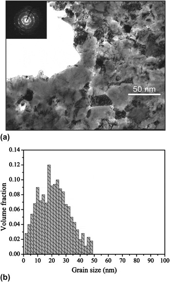
The number of grains with various diameters in nc materials can usually be represented by a log-normal distribution. This particular distribution has also been reported in the literatures to fit real polycrystalline materials.Reference Thorvaldsen33–Reference Ter Heege, De Bresser and Spiers35 Experimental observations on fine-grained polycrystalline metals processed by equal channel angular extrusionReference Youssef, Scattergood, Murty, Horton and Koch36 and inert gas condensationReference Niemana, Weertmana and Siegela37 have found log-normal grain size distributions containing fine grains in the nanometer scale. With log-normal distributions, there must contain some UFNGs with a size of several nanometers. For example, it can be seen from Fig. 1(b) that the volume fraction of grains with a size of 2 nm is ∼2–3% in the specimen with a mean grain size of 23 nm. We suspect that the abundant UFNGs existing in the nc matrix should play an important role in the mechanical behaviors, such as strength and fracture toughness, of nc materials.
(a) Bright-field transmission electron microscope (TEM) image and the selected area diffraction pattern [the upper left inset in (a)] show roughly equiaxed grains with random orientations. (b) Statistical distribution of grain size based on a total grain count of 270 was obtained from multiple dark-field TEM images of the same sample.Reference Kumar, Suresh and Van Swygenhoven3

Many studies have been done to explore the nature of UFNGs. Trelewicz and SchuhReference Trelewicz and Schuh38 evaluated the deformation behaviors of nc Ni–W alloys with grain sizes of 3–150 nm by nanoindentation techniques. They suggested that there is a shift from polycrystal-like to glass-like deformation mechanisms at a grain size of 10–20 nm. GleiterReference Gleiter39 pointed out that these UFNGs exhibit some novel behaviors such as the atomic structure throughout the entire volume of the material and the density of the entire material can be tuned. These properties may be propitious to the nucleation and absorption of dislocations. Gleiter also emphasized that the shift from crystalline state to glass state occurs when the grain size is down to some critical value. Satta et al.Reference Satta, Pisanu, Colombo and Cleri40 inserted a fourth grain into the triple junction location by means of molecular dynamic simulation with the Stillinger–Weber empirical potential and suggested that the central grain could not be stable until the grain size is larger than 6a 0, where a 0 is the lattice constant. However, most of the previous work studied only the UFNGs themselves, instead the influence of UFNGs-induced high strength, adjustable atomic structure, and high volume fraction of triple junctions and grain boundaries (GBs) on the mechanical behaviors of nc matrix.
Bobylev et al.Reference Bobylev, Mukherjee, Ovid’ko and Sheinerman26 suggest a theoretical model that describes the effects of intergrain sliding on the crack growth in nc metals and ceramics. In this model, the stress concentration near cracks initiates intergrain sliding. The model is focused on the intergrain sliding that leads to the generation of dislocations at triple junctions of GBs. These dislocations create stresses that influence crack growth. This process is expected to be applicable to nc solids, which have very large GB and triple junction fractions. It is shown that the intergrain sliding increases fracture toughness by 10–30% in nc Al, Ni, and 3C–SiC. In the spirit of this deformation mechanism, which can lead to crack blunting, the main aim of this study is to describe theoretically how the existence of UFNGs affects the fracture toughness of normal nc materials. More importantly, the dependence of critical crack intensity factor on grain size was calculated, and the results appeared to be much meaningful and inspired. So far, there are few literatures dealing with similar works.
II. GENERATION OF DISLOCATIONS
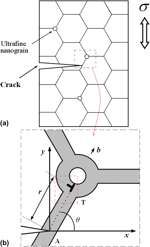
Let us consider a nc solid containing a flat crack with length l. A two-dimensional section of a typical fragment of the solid is schematically shown in Fig. 2(a). The crack intersects the GB at the point distant by r (≪r l) from the nearest triple junction.
Crack in a deformed nanocrystalline (nc) material containing ultrafine nanograins (UFNGs). Inset highlights the formation of an edge dislocation located at the triple junction nearest to the crack tip.
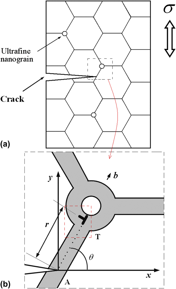
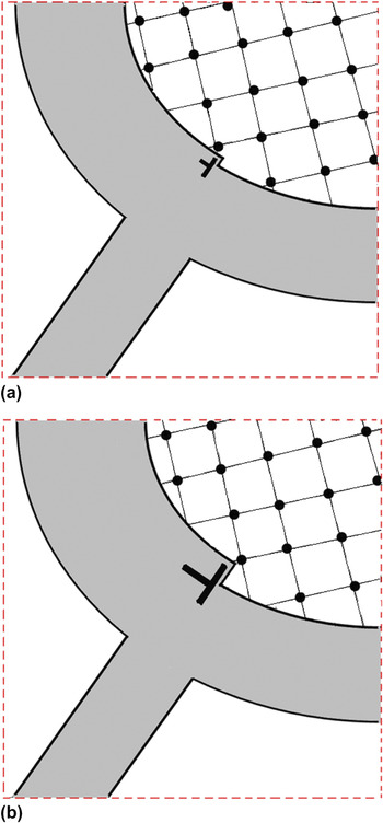
High local stresses operating near the crack tip can initiate intergrain sliding. Following the standard representations of intergrain sliding,Reference Fedorov, Gutkin and Ovid’ko41–Reference Bobylev, Mukherjee and Ovid’ko44 the unfinished plastic shear associated with intergrain sliding is accumulated at the triple junction T. In terms of the theory of defects in solids, the triple junction T contains a dislocation (Fig. 3) whose Burgers vector magnitude gradually grows with increased unfinished plastic shear associated with intergrain sliding.Reference Bobylev, Mukherjee and Ovid’ko44 Here, we assume the situation where intergrain sliding occurs in a part of the boundary, located between the crack tip and a triple junction, and results in the formation of an edge dislocation located at the triple junction nearest to the crack tip.
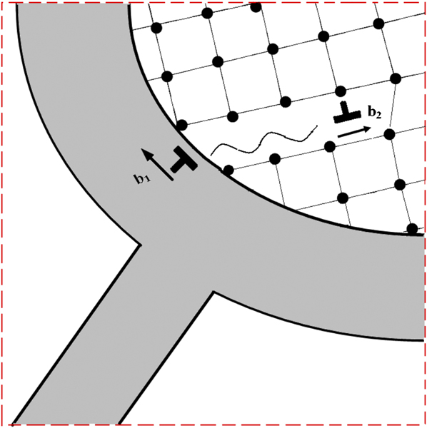
Growth of the Burgers vector magnitude of the triple junction dislocation with increased unfinished plastic shear. This figure is the magnified inset of the part in the red wireframe shown in Fig. 2(b).

It is worth noting that the suggested model (Fig. 2) refers to a rather specialized picture that the UFNGs (just 2–4 nm) stay at the triple junctions of the large grain matrix, which is a special case. We treated the UFNGs as parts of those triple junctions because of their ultrafine size, which play a role of preventing GB dislocations (GBDs) traversing into those triple junctions. It should be noted that the UFNGs are not normal small nanograins, which may facilitate grain boundary sliding (GBS). The UFNGs in normal nanograins matrix can lead to a drastic increase in the overall volume fraction of triple junctions. Fedorov et al.Reference Fedorov, Gutkin and Ovid’ko41 pointed out that the drastic increasing of volume fraction of triple junctions hampers sliding of GBDs at triple junctions, which results in hampering GBS. This can be explained by the following aspects: GB angle, triple junction structure and energy of GBDs sliding through and along the UFNGs, etc. From the mechanical viewpoint, the stress concentration at the UFNGs can not only induce GBS at the UFNGs but also confine the rotation of UFNGs obviously because of their mechanical direction and the ultrafine volume of UFNGs. In addition, GBDs along the UFNGs need to be split frequently because of the special structure. Therefore, both GBDs sliding through and along the UFNGs need much more energy than in the case of normal grain rotation. These actually make the UFNGs to be strong obstacles for GBDs sliding. For simplicity, we take the UFNGs as super triple junctions of overall materials without the consideration of the GBS at UFNGs.
In simulations,Reference Szlufarska, Nakano and Vashista45 partial dislocations in grains were observed to be emitted from amorphous intergranular boundaries connected by stacking faults. Computer simulationsReference Wang, Li, Hamza and Barbee46 have also shown similar partial dislocations emitted from amorphous layers in metallic crystal–glass nanolaminates. In addition, the joining of stacking faults to opposite amorphous layers was experimentally observed in this material after plastic deformation. Bobylev et al.Reference Bobylev, Mukherjee and Ovid’ko44 proposed a theoretical model to describe the emission of partial lattice dislocations from amorphous intergranular boundaries into crystalline grains in deformed nc ceramics. In this model, a dipole of immobile lattice dislocations is generated at an amorphous intergranular boundary through local shear events in this boundary. One of the dislocations then undergoes transformation, resulting in emission of a partial dislocation into the grain interior.
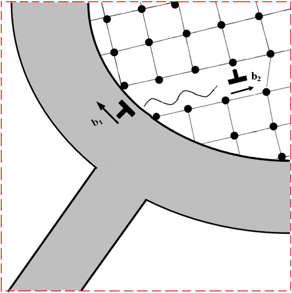
On the basis of the above model, we assume that the Burgers vector magnitude of the triple junction dislocation gradually grows with increased unfinished plastic shear associated with intergrain sliding (Fig. 3), and when the shear stress reaches some critical value τc, the dislocation splits into an immobile edge dislocation and a mobile partial edge dislocation. The glide of the partial dislocation is accompanied by the formation of stacking fault (wavy line) (Fig. 4). The mobile dislocation has the magnitude of Burgers vector b 2 that glides along the crystal slip plane (Fig. 4). The residual dislocation stays at the crystal–glass interface with the magnitude of Burgers vector b 1. At this point, we think that the crack intensity factor reaches its maximum value, and the crack will propagate if the external load continues to increase.
Splitting of one of the dislocations results in the formation of both a residual immobile dislocation and a mobile partial dislocation that glides in a UFNG. The glide of the partial dislocation is accompanied by the formation of stacking fault (wavy line). This figure is the magnified inset of the part in the red wireframe shown in Fig. 3(b).
According to the recently proposed model of Asaro, Krysl, and Kad (AKK)Reference Asaro, Krysl and Kad47 for the emission of partial dislocations, the critical shear stress τc can be calculated by the following equationsReference Asaro, Krysl and Kad47, Reference Zhu, Asaro, Krysl and Bailey48:
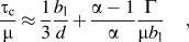

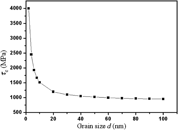
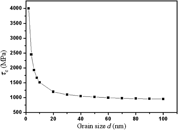
where Γ denotes the stacking-fault energy, d is the grain size, μ is the shear modulus, b 1 is Burgers vector magnitude of the dislocations, and δeq denotes the minimum equilibrium spacing. Figure 5 shows the dependence of critical required shear stress τc on grain size. It can be seen that τc increases with decreased grain size. In particular, when the grain size is down to a few nanometers, there is a sharp increase in τc, which can explain the high strength of the UFNGs.
Dependence of critical shear stress τc on grain size.
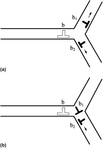
It should be noted that there are other ways of evolution for the dislocation in the triple junctionsReference Fedorov, Gutkin and Ovid’ko41: (i) The dislocation (with Burgers vector b) splits into the two dislocations (with Burgers vectors b 1 and b 2, respectively) that move along the adjacent GBs [Fig. 6(a)]. (ii) The dislocation with Burgers vector b splits into an immobile GBD with Burgers vector b 1, which stays at the triple junction, and a mobile GBD with Burgers vector b 2, which moves along one of the adjacent GBs [Fig. 6(b)]. In this work, we will not consider these two conditions.
Two types of evolution of the triple junction dislocation.

III. EFFECTS OF INTERGRAIN SLIDING ON THE FRACTURE TOUGHNESS OF NC MATERIALS
To consider the effect of triple junction dislocation on the fracture toughness of nc materials, we will use the standard crack growth criterionReference Irwin49 based on the balance between the driving force related to a decrease in the elastic energy and the hampering force related to the formation of a new free surface during crack growth. The criterion can be written asReference Irwin49

where ν is the Poisson ratio, G is the shear modulus, γ is the specific energy of the new free surface, K ‡T and K ‡U are the intensity factors for normal (to the crack line) and shear stresses, respectively. In this study, we assume that the crack growth direction is perpendicular to the direction of the external load. Coefficientsts K ‡T and K ‡U are given as

where  is the intensity factor for the external stress σ0, and
 and
 are the intensity factors for the stresses created by the generated dislocations (Fig. 2).
Within the macroscopic mechanical description, the effect of intergrain sliding, which results in the formation of a dislocation and the emission of dislocation from crack tip, on crack growth can be accounted by effective fracture toughness  . In this case, the crack growth direction is perpendicular to the tensile load direction while the presence of the dislocations just changes the value of
 . In these circumstances, the critical condition for the crack growth can be represented asReference Bobylev, Mukherjee, Ovid’ko and Sheinerman26
 . According to expressions (1)–(3) and the critical condition
 , one finds the following expression for factor
 :

Next, we will calculate the stress intensity factors  and
 . In doing so, as shown in Fig. 2(b), b denotes the Burgers vector magnitude of the edge dislocation, G is the shear modulus, ν is the Poisson ratio, r 0 is the distance between the edge dislocation and the crack tip, and θ is the angle made by the boundary plane (the dislocation Burgers vector) and the coordinate axis Ox. The stress intensity factors
 and
 for the dislocation-induced stresses can be calculated based on Zhang and LiReference Zhang and Li50 by
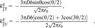
where

It should be noted that in the present model, the Burgers vector magnitude b is arbitrary and it gradually grows with increased unfinished plastic shear associated with intergrain sliding because it characterizes a noncrystallographic dislocation.Reference Bobylev, Mukherjee and Ovid’ko44 In the quasiequilibrium state, the Burgers vector magnitude b corresponds to a minimum of the energy change ΔW associated with the dislocation generation process (Fig. 1). Following Ref. Reference Bobylev, Mukherjee, Ovid’ko and Sheinerman26, the energy change ΔW can be written as

where r c is the dislocation core radius, and r 0 is the distance between the crack tip and the nearest triple junction.
With the condition ∂(ΔW) / ∂b = 0 of the minimum of the energy change ΔW, one finds the following expression for the dislocation Burgers vector magnitude b:

Here,
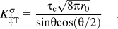
In the above formulas, the distance between the crack tip and the nearest triple junction, denoted as r 0 as shown in Fig. 1, is not directly related with the grain size d. Since the range of r 0 is limited in 0 < r 0 ≤ d / 2, to establish the relationship between d and  , we take r 0 = ϕd / 2, where 0 < ϕ ≤ 1.
IV. RESULTS AND DISCUSSION
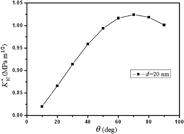
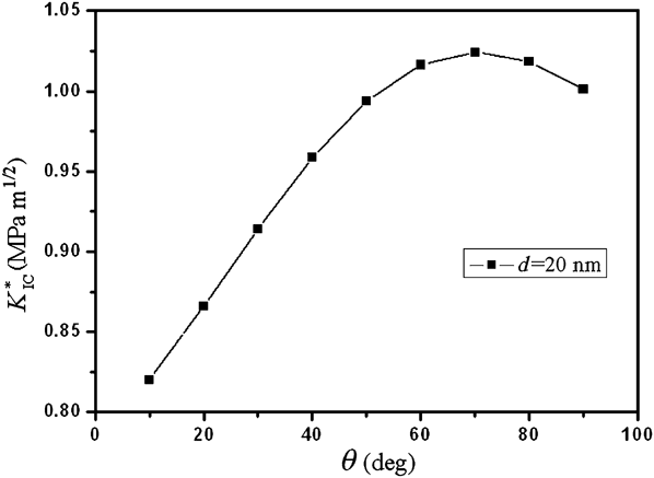
In the case without UFNGs, we have calculated the critical crack intensity factor  as a function of θ for nc Ni with a grain size of 20 nm (Fig. 7). The typical values of parameters of nc Ni are as follows: G = 73 GPa , ν = 0.34, and γ = 1.725 Jm-2. It can be seen from Fig. 7 that the
 reaches the maximum value when the boundary plane makes the angle θ of around 70° with the direction of crack growth. This is because the stress
 reaches its maximum when the plane makes the angle of 70°with the direction of crack growth. It should be noted that these values are still very small. In particular, they are more than an order of magnitude smaller than the experimental values. This is because in calculating these values, we have taken into account only one dislocation emission and only along one slip plane. Apparently, accounting for a number of dislocation emissions along multiple slip planes would increase the calculated values of
 .
The dependence of critical crack intensity factor  on the angle
 made by the boundary plane and the crack growth direction.
To characterize the effect of dislocations produced by intergrain sliding on crack growth, one should compare the value of  with the fracture toughness
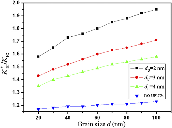
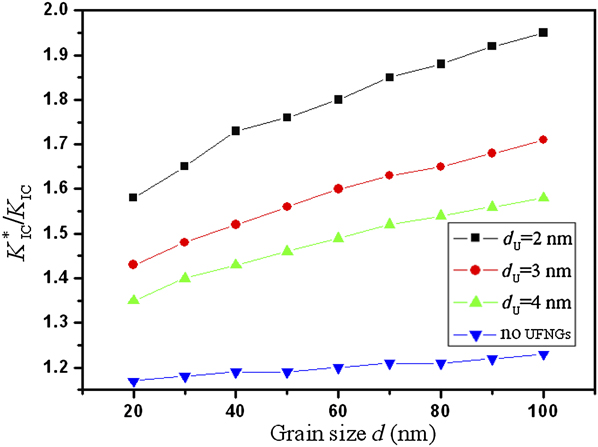
 in the dislocation-free case, that is, the case of brittle fracture with the intergrain sliding being completely suppressed. Figure 8 shows the dependence of the ratio of
 on the grain size of UFNGs and nc matrix. It demonstrates that:
(i) In the case without UFNGs, intergrain sliding can increase the fracture toughness by 11–13%.
 slightly increases with grain size.
(ii) Owing to the existence of UFNGs, fracture toughness increases obviously compared with the case without UFNGs. For example, in the sample composed of UFNGs with size of 2 nm evenly distributed in the nc matrix with grain size of 100 nm, the fracture toughness increases nearly 100%; this is in agreement with the previous inference that the UFNGs can enhance the fracture toughness of nc materials.
(iii) Under the condition that the size of UFNGs being fixed,
will increase with the increasing of nc grain size. For instance, when the size of UFNGs being fixed at 2 nm, can grow up by 26% with nc grain size increasing from 20 to 100 nm. Conversely, a decrease in grain size of the nc matrix dramatically decreases and thus makes the materials much more brittle. This is in agreement with the experimental fact that some nc metals with a face-centered cubic lattice exhibit a ductile-to-brittle transition with decreasing grain size.Reference Li and Ebrahimi51–Reference Ebrahimi, Liscano, Kong, Zhai and Li53(iv) When the grain size of the nc matrix is consistent,
decreases with increased size of UFNGs. For example, when the grain size of nc matrix is fixed at 100 nm while the size of UFNGs increases from 2 to 4 nm, decreases by 28%. This is because the smaller the grain size, the higher the critical stress τc, as shown in Fig. 5.
 slightly increases with grain size.
 will increase with the increasing of nc grain size. For instance, when the size of UFNGs being fixed at 2 nm,
 can grow up by 26% with nc grain size increasing from 20 to 100 nm. Conversely, a decrease in grain size of the nc matrix dramatically decreases
 and thus makes the materials much more brittle. This is in agreement with the experimental fact that some nc metals with a face-centered cubic lattice exhibit a ductile-to-brittle transition with decreasing grain size.
 decreases with increased size of UFNGs. For example, when the grain size of nc matrix is fixed at 100 nm while the size of UFNGs increases from 2 to 4 nm,
 decreases by 28%. This is because the smaller the grain size, the higher the critical stress τc, as shown in
 as a function of grain size for various UFNGs sizes in nc Ni.
It should be noted that, in this work, we consider only the nc matrix with a grain size between 20 and 100 nm. This grain size range is selected on the basis of the following reasons: (i) In nc materials with a grain size below 20 nm, plastic deformation is believed to be dominated by such mechanisms as GB sliding, GB diffusional creep, stress-driven GB migration, twin, and rotation deformation modes, rather than by lattice dislocation slip.Reference Meyers, Mishra and Benson1, Reference Shen, Koch, Tsui and Pharr2, Reference Tomar and Zhou5, Reference Jiang and Weng9, Reference Tvergaard and Hutchinson29, Reference Zhan, Kuntz and Mukherjee54, Reference Han, Lavernia and Mohamed55 (ii) As grain size d increases, GB dislocation climb becomes too slow to fully accommodate intergrain sliding and can no more promote crack blunting. At the same time, the suggested model is not applicable to the solids with a grain size above a hundred nanometers.
V. CONCLUSIONS
We have developed a theoretical model to study the critical stress intensity factor  (which characterizes toughness) of nc materials in a typical situation where UFNGs (2–4 nm) are homogeneously embedded in the nc (20–100 nm) matrix. The processes of crack blunting and propagation are controlled by intergrain sliding in the vicinities of the crack tips. The mechanism involves the intergrain sliding, which generates dislocations at the triple junctions of GBs creating stresses that influence crack growth. We found that the introduction of UFNGs can effectively enhance the fracture toughness of nc matrix materials. For instance, the fracture toughness can be doubled with the introduction of UFNGs (2 nm) in the nc (100 nm) matrix. In addition, the toughening effect of the UFNGs is sensitive to the size of nanograins. For example, decreasing the nanograin size from 4 to 2 nm increases
 (the ratio of critical stress intensity factor to fracture toughness) by 28% and thus dramatically enhances the toughness of the nc (100 nm) matrix material.
ACKNOWLEDGMENTS
The authors are grateful for the funding of the National Natural Science Foundation of China (10502025 and 10872087) and the Natural Science Foundation of Jiangsu Province (BK2007528).