1. Introduction
The human hand is one of the most important systems for us to interact with the environment because it provides sensory and tactile feedback, as well as the ability to manipulate objects. Studies have shown that an average person grasps 1500 times a day with their hands [Reference Zheng, De La Rosa and Dollar1]. However, millions of people around the world suffer from hand dysfunction, and this number is growing. Healthy hand function is the main factor in whether a person can live independently. Loss of some or all finger movement ability will make it impossible for a person to complete daily life activities normally, reducing the patient’s quality of life [Reference Haarman, Hekman, Rietman and Van Der Kooij2]. Finger spasticity is one of the common sequelae of stroke and one of the most important factors causing limb movement disorders. It is mainly manifested as the inability to flex and extend the fingers, resulting in spasticity and increased muscle tension [Reference Barry, Kamper, Stoykov, Triandafilou and Roth3]. If the spastic state lasts for a long time, the spastic muscles and surrounding soft tissues will begin to contract, seriously affecting hand function. Tardieu C et al. believe that static stretching can promote muscle growth and reduce the responsiveness of stretch reflexes. Stretching for several hours a day can effectively relieve spasticity [Reference Li, Cheng, Gao, Lu and Zhao4].
Studies have shown that patients can significantly improve their hand motor function by performing repetitive rehabilitation training of a certain intensity with the assistance of robots [Reference Zhu, Wu, Chen, Zhao and Liang5]. In addition to being an auxiliary means of rehabilitation treatment, hand rehabilitation robotic devices can also provide assistance to stroke patients who have permanently lost hand function or whose hand function has weakened. Hand rehabilitation exoskeletons are of great significance in reducing the pressure on rehabilitation physicians and restoring human health [Reference Noronha and Accoto6].
Hand rehabilitation exoskeletons can be divided into rigid exoskeletons and flexible exoskeletons in terms of structural form. Rigid hand exoskeletons use rigid mechanisms such as connecting rods, gears, and sliders. This structure has accurate transmission and precise control, but its adaptability is poor, and its interaction with the human body is not smooth, so it is easy to cause damage to the wearer’s hand. For example, Guo et al. developed an exoskeleton glove system with a link drive, and the link mechanism was designed on the side of the finger rather than above. The drive part was placed on the forearm, effectively reducing the size of the exoskeleton glove and improving the compactness of the exoskeleton structure [Reference Iqbal, Tsagarakis, Fiorilla and Caldwell7]. Yang et al. developed a portable force-recognizing exoskeleton that uses gears to ensure the accuracy of force and movement, and its structure is relatively complex [Reference Yang, Zhang, Zhu and Fu8].
Due to the complexity and inter-subject variability of human finger bone kinematics, self-alignment of human exoskeleton axes is a challenging task in rigid exoskeleton design. Axis misalignment can produce undesirable forces on finger joints, which can cause harm to the user [Reference Cempini, de Rossi, Lenzi, Vitiello and Carrozza9]. Therefore, designers must consider the problem of human exoskeleton joint axis misalignment when designing hand exoskeletons. Li et al. designed an interactive hand exoskeleton by directly matching the device’s joint axes with the joint axes of the corresponding finger joints [Reference Hong, Kim, Ihn, Jeong and Kim10]. Hong et al. designed an index finger exoskeleton by aligning one side of the user’s finger with the joint rotation axis [Reference Hong, Kim, Ihn, Jeong and Kim10]. Wang et al. proposed an underactuated link-slide mechanism that can directly coincide with the human finger joints [Reference Wang, Meng, Meng, Li and Yu11]. Ho et al. designed a circular track mechanism with a virtual center that directly aligns the joint rotation axis [Reference Sun, Wang, Cheng, Li, Niu, Sun and Li12]. However, due to the soft tissue or inter-subject variability of human finger joints, the axes of the finger joints are variable. The above devices cannot guarantee the self-alignment capability of the exoskeleton joint axes. Therefore, it still causes inconvenience to patients and often has a complex structure. Li et al. developed a thumb exoskeleton that combines a spatially adaptive mechanism with a spherical mechanism. The passive joints exploit configuration-based spatial adaptation to enable flexible motion and compensate for joint axis misalignment, providing independent thumb assistance across three degrees of freedom [Reference Li, Cheng, Gao, Xia and Jiang13]. Sun et al. presented an index finger exoskeleton employing a "serial–parallel MCP closed-loop kinematic chain + serial PIP closed-loop kinematic chain," where passive joints accommodate positional deviations of the finger joint axes through their inherent mobility [Reference Sun, Wang, Cheng, Li, Niu, Sun and Li12]. These designs, however, are confined to single fingers and have not been generalized to all digits, precluding full-hand coordination.
Flexible hand exoskeleton refers to a series of exoskeleton robots that use flexible components such as springs, cables, and pneumatic muscles to transmit and drive finger movements. Compared with rigid hand exoskeletons, flexible exoskeletons have a good performance in aligning with human hand joints, have a higher degree of fit with the human hand, and are more flexible in movement, more comfortable, and safer. At the same time, flexible hand exoskeletons are simpler in structure and lighter in weight. For example, Nycz et al. developed a cable-driven glove with a double-layer elastic leaf spring structure for hand rehabilitation, which can be remotely driven [Reference Nycz, Butzer, Lambercy, Arata, Fischer and Gassert14]. Bützer et al. made some improvements to the double-layer leaf spring structure and added a thumb module [Reference Bützer, Lambercy, Arata and Gassert15]. Li et al. changed the parallel double-layer leaf spring structure to a non-parallel double-layer leaf spring structure, thereby improving the stiffness and load-to-mass ratio of the fingers [Reference Li, Cheng and Zhang16]. Popov et al. developed the cable-driven flexible exoskeleton glove Graspy Glove [Reference Liang, Xu, Li, He and Khalique17]. In et al. developed a cable drive system to help patients with hand injuries grasp movements [Reference Haarman, Hekman, Rietman and Van Der Kooij2]. Renghao et al. developed a pseudo-rigid-body model that integrates a topology-optimized compliant mechanism with a large-displacement flexible hinge, producing a flexible finger rehabilitation exoskeleton that tracks human fingertip trajectories and conforms to the index finger [Reference Liang, Xu, Li, He and Khalique17]. While these designs offer some benefit for hand rehabilitation, they do not adequately address the need for passive extension in patients with finger spasticity. Haarman et al. created a flexible structure using flexible bending elements, cables, and magnetic connectors to form a hand rehabilitation exoskeleton that assists finger extension in severe stroke patients without applying axial forces to the fingers [Reference Haarman, Hekman, Rietman and Van Der Kooij2]. Nevertheless, this configuration cannot provide independent extension control for multiple fingers. Chen et al. made a soft glove system and a special thumb mechanism, which is driven by cables and has good adaptability and flexibility [Reference Chen, Li, Li, Wang, Yu, Wang, Xue, Zhao and Liu18]. Sui et al. designed a soft glove with shape memory alloy as the power and cable drive. The joints are connected by a serpentine fold structure to ensure that the human finger joints can bend smoothly and can adapt well to the rotation axis of the patient’s finger joints [Reference Sui, Ouyang, Jin, Chai, Wei, Li, Xu, Li, Wang and Zhang19]. Agostino Stilli and others designed a new type of lightweight inflatable soft exoskeleton device, called AirExGlove, to provide high-dose, adaptive, and progressive rehabilitation treatment for patients affected by clenched fist deformity [Reference Stilli, Cremoni, Bianchi, Ridolfi, Gerii, Vannetti, Wurdemann, Allotta and Althoefer20].
Shape memory alloy (SMA) actuators, which rely on material deformation at critical temperatures for operation, are known for their high power-to-weight ratio. However, their motion presents significant nonlinearities, hysteresis, and saturation, introducing substantial challenges in control. Conversely, cable-driven exoskeletons (CDEs), utilizing cables for force transmission, exhibit more linear and predictable mechanical properties. They offer an extended range of motion and can be readily managed with traditional control algorithms. Additionally, CDEs provide design flexibility to accommodate a wide variety of human movements, thereby enhancing user comfort and system performance. When comparing pneumatic hand exoskeletons to CDEs, the former present several drawbacks. Their soft actuators, often constructed from materials such as silicone, display high nonlinearity, which complicates the modeling process. Most pneumatic systems employ feedforward control without the integration of sensor feedback. In sharp contrast, CDEs can effectively incorporate sensor feedback. The control of pneumatic pressure is challenging due to its nonlinear characteristics and complex dynamics, leading many studies to adopt fixed pressure values. On the other hand, CDEs can precisely regulate cable tension through motor control and other methods, achieving more flexible and accurate motion control.
This paper proposes a flexible hand exoskeleton based on a composite drive of cables and leaf springs, which addresses the limitation of current hand exoskeletons in enabling patients with finger spasms to achieve independent extension control across multiple fingers. The hand exoskeleton can adapt to different finger sizes of the human body and is easy to disassemble to replace the elastic elements. Section 2 introduces the design basis of the exoskeleton and the overall structure of the exoskeleton. Then, according to the characteristics of human fingers, the DH parameter method is used in Section 3 to establish the kinematic model of the fingers, and a static analysis based on the leaf spring and elastic band is carried out. Finally, a prototype is made, and the performance test of the prototype is carried out, and relevant performance parameters are proposed to evaluate it (Figure 1).
Some existing wearable robotic systems for hand assistance and rehabilitation.

2. Structural design of exoskeletons for hand rehabilitation
2.1. Exoskeleton hand design basis meter
Figure 2 shows the skeletal tendon structure of human fingers. The finger skeleton consists of the distal interphalangeal joint (DIP), the proximal interphalangeal joint (PIP), the metacarpophalangeal joint (MCP), and the distal, middle, and proximal phalanges [Reference Jiang, Yamanoi, Chen, Yong, Li, Yokoi and Jing21]. The MCP has two degrees of freedom, and the DIP and PIP each have one degree of freedom. After ignoring the swinging degrees of freedom of the MCP that are not related to finger flexion and extension, the finger skeleton structure is simplified to a three-degree-of-freedom planar linkage. The flexion and extension movement of the finger is powered by the contraction of the muscles located in the forearm. The muscles pull the finger skeleton to move through the flexor tendons of the profundus, the flexor tendons of the superficial digitorum, and the extensor tendons of the digitorum. When the finger flexes, the flexor tendons of the profundus and superficial digitorum pull the phalanges of the finger. When the finger extends, the extensor tendons of the digitorum pull the distal phalanges so that the three joints of the finger rotate synchronously to complete the finger extension.
Physiological structure of finger bones.

The target users of this design are patients whose fingers are unable to flex or extend autonomously due to factors such as stroke. In order to achieve the purpose of hand rehabilitation, the hand exoskeleton must be small and light, with flexible finger movements, able to overcome the patient’s contracture tension, and generate sufficient force to assist the user in completing simple daily grasping movements. The hand function rehabilitation exoskeleton device is used to assist the affected hand in static stretching and continuous passive motion (CPM) rehabilitation training. CPM theory refers to a rehabilitation training method that passively moves the patient’s joints in a predetermined sequence within a specified time length with the help of a therapist or a rehabilitation robot. The external force applied to the patient’s joints should not be greater than the physiological value, and the freedom of the joint’s own movement should be strictly observed. CPM theory has been proven to be effective for patients with nerve damage, and CPM rehabilitation training does not require high-precision motion trajectories [Reference Uetsuji, Kingsuvangul, Boonyasurakul and Charoensuk22–Reference Harvey25].
The design scheme of this paper is to use a high-rigidity leaf spring with an elastic band to keep the fingers of contracture patients in an extended state without the action of external force and use a flexible cable to simulate the flexor tendon of the finger to drive the finger to bend. The bending angle of the finger is regulated by adjusting the driving force to reconstruct the patient’s motor nerves and promote the patient’s rehabilitation.
2.2. Exoskeleton hand structure program
In exoskeletons made of elastic elements, most of them use a double-layer leaf spring push-pull structure (as illustrated in Figure 3(a)). This configuration consists of a lower fixed reed and an upper sliding reed. When an external force acts on the upper reed, it slides to assist finger flexion or extension while simultaneously storing or releasing elastic potential energy. The fixed lower reed constrains the displacement range of the upper reed, thereby limiting the finger’s motion stroke. A single-layer leaf spring configuration, shown on the left of Figure 3(b), incorporates only a single sliding reed. Without the constraint of a fixed lower reed, this design allows each finger joint to achieve a greater bending angle, expanding the finger’s motion space. However, the absence of a fixed layer causes the exoskeleton finger segment to displace along the direction of finger motion during bending. Table I shows the respective advantages and disadvantages of the two types of leaf springs. To overcome the limited motion space of the double-layer reed and the sliding tendency of the single-layer design, an improved configuration was developed, illustrated on the right of Figure 3(b). This modified design adds an elastic band layer to the original single-layer reed. During finger bending, the elastic band’s tension, combined with the friction between the exoskeleton and the phalanx, effectively counteracts the forward sliding and stacking of the exoskeleton segment. Moreover, this improved configuration maintains the single-layer design’s advantage of a larger motion space. The upper and lower phalangeal blocks are connected by Velcro, providing strong adaptability to different finger sizes. Adjusting the elastic band’s length alters the distance between the blocks to accommodate various finger dimensions. This inherent flexibility improves user comfort.
Advantages and disadvantages of single-layer leaf springs and double-layer leaf springs.

Comparison of double-layer leaf spring and single-layer leaf spring structures.

Figure 4(a) shows the overall structure of the hand exoskeleton designed with a single-layer leaf spring in this paper, including the hand wearable part, the arm guide ring, and the drive device. Figure 4(b) is a schematic diagram of the exoskeleton hand structure, which is roughly composed of three layers: the first layer is composed of reeds and elastic bands, which provide passive elastic force for the exoskeleton hand. One end of the leaf spring is fixed in the distal phalanx block, and the other end can slide. The elastic band is connected between each adjacent phalanx block for an auxiliary role, making the leaf spring easier to recover. The second layer is the wearable layer, which is surrounded by upper and lower phalanx blocks and Velcro. The third layer is the cable hole and nylon tube for guiding the cable transmission. The exoskeleton adopts a cable drive method, and the cable slides in the nylon tube. One end of the cable is fixed on the fingertip, passes through the guide holes on the three lower phalanx blocks in turn, and then connects to the drive device through the guide tube.
Rehabilitation exoskeleton hand design scheme.

The structure of the exoskeleton finger part is basically the same. Taking the index finger as an example, it contains three phalanges, corresponding to the three phalanges of the human hand. Each phalange block is composed of an upper and lower part and Velcro. The enclosed area is worn on the phalanges of the patient’s fingers, and the area enclosed by the fingertips is closed to prevent the exoskeleton from being separated from the patient’s fingers during the driving process. A guide hole for the cable is set in the lower part of the phalange block to guide the cable to the palm. The leaf spring is only fixed in the distal phalange block and can slide into the remaining phalanges. Based on the palm cover, a base plate is installed on the back of the palm cover as a frame. Considering the bending of the palm, the back of the hand base plate is divided into two parts. Each part connects and fixes two fingers (the thumb is connected separately). The cable guide plate is installed on the palm side of the palm cover to guide the reasonable path of the cable.
The cable imitates the flexor tendon in the finger structure and is arranged on the palm side. Each of the five fingers is driven by a cable. The five cables pass through the guide hole of the lower phalanx block to reach the palm. The cables slide in the nylon tube. The tube of the cable in the palm is constrained by the guide block fixed on the palm side of the glove. Unreasonable cable arrangement may cause discomfort to the patient’s fingers during driving, so the following requirements are put forward for flexible cable arrangement:
-
(1) The five cables cannot conflict with each other.
-
(2) The traction direction of cables must conform to the movement characteristics of the fingers to prevent damage to the fingers.
-
(3) The flexible cable path should be as small as possible, and the flexible cable turning angle should not be as sharp as possible to prevent excessive sliding friction.
When the proximal joint of the finger is bent, the palm will bend. Therefore, when arranging the palm guide, it is necessary to follow the physiological characteristics of the palm so that the palm guide does not affect the flexibility of the palm as much as possible. Studies have found that the movement of the palm is related to the palm flexor line. When the palm is bent, it will bend along the flexor line on the inside of the palm. Generally speaking, the palm flexor lines mainly include the distal flexor line, the proximal flexor line, and the longitudinal flexor line. In order to reduce movement interference and ensure the flexibility of the hand, the four-finger guide is arranged on the upper side of the proximal flexor line of the palm, and the thumb guide is placed in the area surrounded by the proximal flexor line and the longitudinal flexor line. The palm cable guide method finally adopted by the exoskeleton through analysis is shown in Figure 5.
Schematic diagram of the flexor line and flexor arrangement of the hand.

3. Kinematics and mechanics analysis of exoskeleton for hand rehabilitation
3.1. Exoskeleton kinematics modeling
The hand rehabilitation exoskeleton finger module can be simplified into a series-link model. The phalanges are assumed to have equal thickness, and the error caused by the phalange thickness is converted to the height of the guide hole. Under the traction of the cable, the exoskeleton generates motion. The model of a single finger is shown in Figure 6. The endpoints of the guide hole of the flexible cable are represented by P 1∼P 7, and the traction points of the moving platform are represented by P 1∼P 7. The global coordinate system is O-X 0 Y 0 Z 0, and the rest are local coordinate systems.
Single-finger model.

The DH method is used to establish the coordinate system at each joint, and the transformation matrix of the adjacent coordinate system is:
 \begin{equation} \left\{\begin{array}{l} ^{2}T_{3}=tran_{x}\left(a_{2}\right)rot_{z}\left(\theta _{3}\right)\\[4pt] ^{1}T_{2}=tran_{x}\left(a_{1}\right)rot_{z}\left(\theta _{2}\right)\\[4pt] ^{0}T_{1}=rot_{z}\left(\theta _{1}\right) \end{array}\right. \end{equation}
Assume that the thickness of the proximal finger, middle finger, and distal finger are t 1, t 2, and t 3, and the heights are b 1, b 2, and b 3, respectively. Calculate the coordinates of each point in the base coordinate system:
 \begin{align} \left\{\begin{array}{l} P_{1}=\left[-l_{0} \quad \dfrac{b_{0}}{2} \quad 0\right]^{T} \\[8pt] P_{2}=\left[l_{1}\mathrm{c}_{1}-\dfrac{b_{1}}{2}\mathrm{s}_{1} \quad l_{1}\mathrm{s}_{1}+\dfrac{b_{1}}{2}\mathrm{c}_{1} \quad 0\right]^{T} \\[8pt]P_{3}=\left[\left(l_{1}+t_{1}\right)\mathrm{c}_{1}-\dfrac{b_{1}}{2}\mathrm{s}_{1} \quad \left(l_{1}+t_{1}\right)\mathrm{s}_{1}+\dfrac{b_{1}}{2}\mathrm{c}_{1} \quad 0\right]^{T} \\[8pt]P_{4}=\left[a_{1}\mathrm{c}_{1}+l_{2}\mathrm{c}_{12}-\dfrac{b_{2}}{2}\mathrm{s}_{12} \quad a_{1}\mathrm{s}_{1}+l_{2}\mathrm{s}_{12}+\dfrac{b_{2}}{2}\mathrm{c}_{12} \quad 0\right]^{T} \\[8pt]P_{5}=\left[a_{1}\mathrm{c}_{1}+\left(l_{2}+t_{2}\right)\mathrm{c}_{12}-\dfrac{b_{2}}{2}\mathrm{s}_{12} \quad a_{1}\mathrm{s}_{1}+\left(l_{2}+t_{2}\right)\mathrm{s}_{12}+\dfrac{b_{2}}{2}\mathrm{c}_{12} \quad 0\right]^{T} \\[8pt]P_{6}=\left[a_{1}\mathrm{c}_{1}+a_{2}\mathrm{c}_{12}+l_{3}\mathrm{c}_{123}-\dfrac{b_{3}}{2}\mathrm{s}_{123} \quad a_{1}\mathrm{s}_{1}+a_{2}\mathrm{s}_{12}+l_{3}\mathrm{s}_{123}+\dfrac{b_{3}}{2}\mathrm{c}_{123} \quad 0\right]^{T} \end{array}\right. \end{align}
Taking the original length of the cable as
 $\left\| P_{0}P_{7}\right\|$
, then the length of the flexible cable S is expressed as:
 \begin{equation} S=\left.\left\| P_{0}P_{7}\right.\right\| =t_{3}+l_{3}+a_{2}+a_{1}+l_{0}+t_{0} \end{equation}
The elastic deformation of the flexible cable under tension is negligible, and the contraction of the flexible cable is as follow:
 \begin{equation} {\unicode[Arial]{x0394}} L=S-t_{0}-t_{1}-t_{2}-t_{3}-\left| \begin{array}{l} P_{1}P_{2} \end{array}\right| -\left| \begin{array}{l} P_{3}P_{4} \end{array}\right| -\left| \begin{array}{l} P_{5}P_{6} \end{array}\right| \end{equation}
Write the length change of the cable as the relationship between the bending angles of the three joints of the finger:
 \begin{equation} {\unicode[Arial]{x0394}} L=f\left(\theta _{1},\theta _{2},\theta _{3}\right) \end{equation}
Thus, the mapping relationship between the contraction of the cable and the bending angle of the finger is obtained.
When the exoskeleton is not worn, according to the coordinate system established in Figure 6, the coordinates of the fingertip coordinate P8 are as follows:
 \begin{eqnarray} P_{8}&=&\left[\alpha _{1}\cos \theta _{1}+\alpha _{2}\cos \left(\theta _{1}+\theta _{2}\right)+\alpha _{3}\cos \left(\theta _{1}+\theta _{2}+\theta _{3}\right) \quad \alpha _{1}\sin \theta _{1}+\alpha _{2}\sin \left(\theta _{1}+\theta _{2}\right)\right.\nonumber\\&&\left.+\alpha _{3}\sin \left(\theta _{1}+\theta _{2}+\theta _{3}\right)0\right]^{T} \end{eqnarray}
Assuming that the length of the proximal phalanx of the index finger is a 1 = 47 mm, a 2 = 30 mm, and a 3 = 25 mm, in order to obtain the spatial range reached by the finger during movement, Matlab is used to cyclically assign values to θ 1, θ 2, and θ 3 to calculate the coordinate points of the finger end position. Taking the index finger as an example, the graph of the index fingertip in all positions in space can be obtained with the MCP as the origin, as shown in Figure 7a.
Finger motion space.

Figure 7 shows the finger movement space under theoretical conditions and artificial consciousness. Due to the coupling of the finger joints in bending, the finger cannot reach the theoretical space without the help of external force. Tests on the index finger found that the three joints were coupled under natural bending, whereas the PIP and DIP joints were coupled under conscious control, whereas the MCP joints could be uncoupled. Compared with the case without a hand exoskeleton, the flexibility of the human hand is reduced after wearing the exoskeleton due to the increase in the volume of the human hand. When the fingers move, certain constraints will be imposed on the fingers, and the fingertip space will also be reduced accordingly.
According to the structural characteristics of the hand exoskeleton designed in this paper, the following constraints are introduced:
Constraint 1: Spring elongation length
Constraint 2: Neighboring phalangeal block contact interference
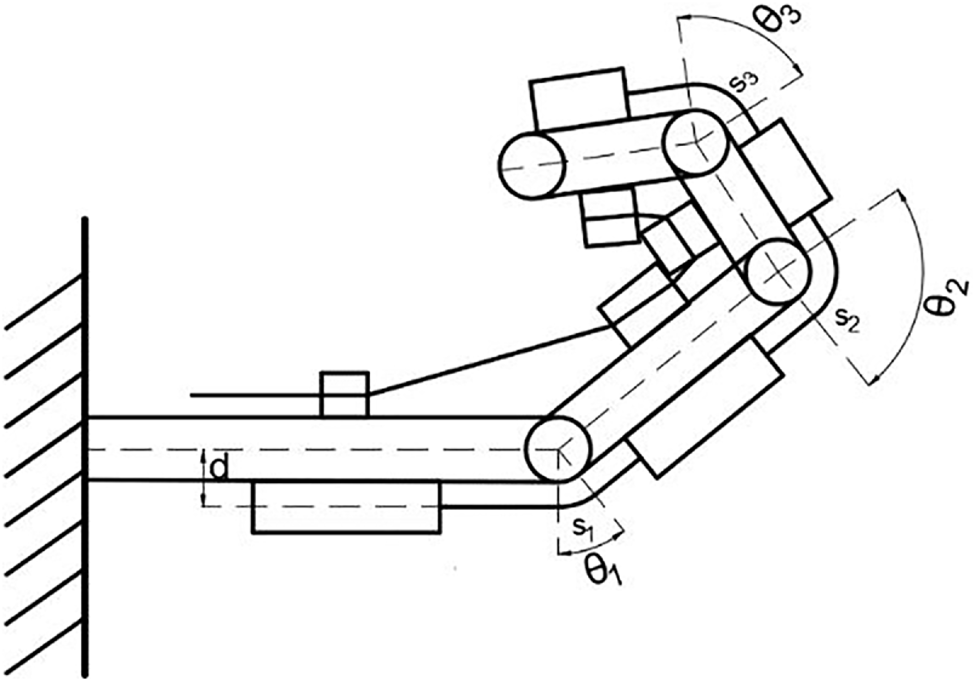
The leaf spring elongation length is related to the bending angle θ of the finger and the height d from the finger, assuming that the curved portion of the reed bends with equal curvature, as shown in Figure 8.
Interference state of finger bone blocks with each other.

The elongation s is when the leaf spring is bent with equal curvature:
 \begin{equation} s=\frac{\theta \pi d}{360^{\circ}} \end{equation}
Take the maximum flexion angle of the finger joints when wearing the exoskeleton:θ 1 = 70°, θ 2 = 90°, θ 3 = 60°.
When the thickness or length of the guide block is too large in finger flexion it causes interference with the phalangeal block, and the flexion state of each joint is shown in Figure 8:
Due to the mutual interference of the phalanges, continuing to increase the cable tension finger will not continue to bend; at this time, the maximum bending angle of the three joints is as follows: θ 1 is not affected by the size of the phalangeal block, considering the remaining two joints.
 \begin{equation} \left\{\begin{array}{l} \theta _{1}=70^{\circ}\\[6pt] 90^{\circ}\leq \theta _{2}=\arctan \dfrac{l_{2}}{b_{2}+r_{2}}+\arctan \dfrac{a_{1}-l_{1}-t_{1}}{b_{1}+r_{2}^{\mathit{'}}}\\[10pt] 60^{\circ}\leq \theta _{3}=\arctan \dfrac{l_{3}}{b_{3}+\sqrt[r]{2}}+\arctan \dfrac{a_{2}-l_{2}-t_{2}}{b_{2}+\sqrt[r]{2}} \end{array}\right. \end{equation}
where r is the simplified connecting rod thickness, when designing the dimensions, the relevant dimensional parameters are selected in such a way that they do not interfere with the maximum angle.
3.2 Leaf spring analysis
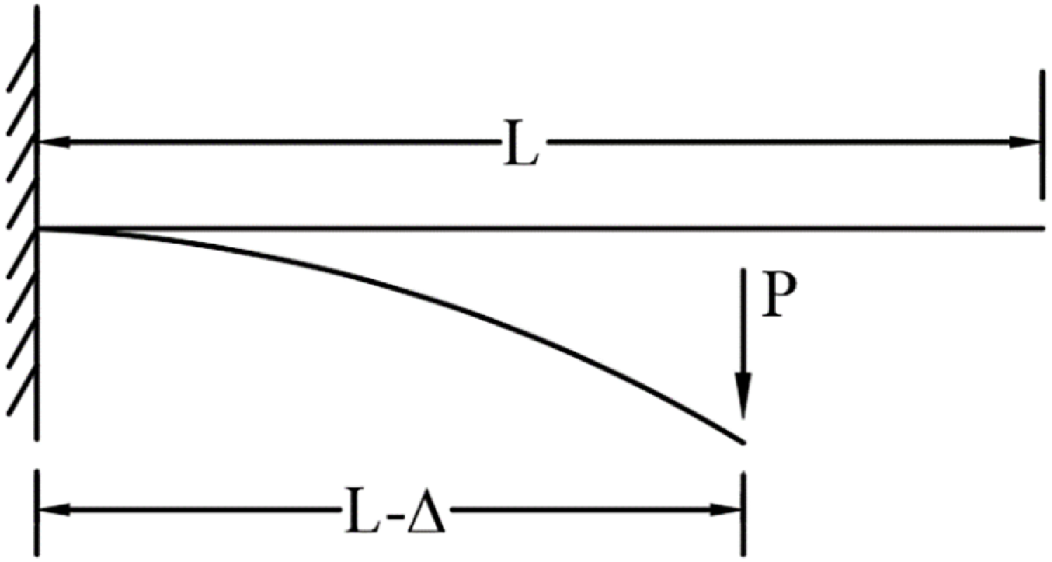
In the designed exoskeleton hand, leaf springs act as an elastic element in the designed hand exoskeleton, taking part of the role of unfolding the curved fingers by simplifying the leaf spring into a cantilever beam model as shown in Figure 9.
Bending cantilever model of leaf spring.

In the design of the exoskeleton structure, the failed spring piece can be easily replaced in time, so the fatigue bending creep of the leaf spring is not considered in the analysis. Leaf spring bending is a large deflection problem and is derived based on the Bernoulli-Euler theorem [Reference Bisshopp and Drucker26]. Let B = EI
 \begin{equation} B\frac{d\phi }{ds}=P\left(L-{\unicode[Arial]{x0394}} -x\right)=M \end{equation}
Solving this differential equation eventually yields:
 \begin{equation} P\left(L-{\unicode[Arial]{x0394}} \right)=B\left(\frac{d\phi }{ds}\right)_{\phi =0}=B\sqrt{\frac{2P\sin \phi _{0}}{B}} \end{equation}
For the leaf spring used, since the initial state is rectangular between the finger bones and the bending elongation part, the leaf spring cross-section is the same rectangular, and the following spring bending elasticity calculation can be carried out:
 \begin{equation} I=\frac{w\ast h^{3}}{12} \end{equation}
 \begin{equation} P=\frac{2EI\phi _{0}}{\left(L-{\unicode[Arial]{x0394}} \right)^{2}} \end{equation}
Assuming that the curved part is of constant curvature,
 \begin{equation} L-{\unicode[Arial]{x0394}} =\frac{L}{\phi _{0}}\sin \phi _{0} \end{equation}
we get
 \begin{equation} P=\frac{2EI\phi _{0}^{2}}{L^{2}\sin \phi _{0}} \end{equation}
E: modulus of elasticity, I: moment of inertia of a rectangular section, w: width of the leaf spring, h: thickness of the leaf spring, P: applied load.
Bending spring force of leaf spring from hydrostatic equilibrium: T = P. Different sizes of leaf springs produce large differences at the moment on the end of the finger in patients with constriction, and the change in stiffness is observed by changing the size of the leaf spring to determine the appropriate leaf spring size. Define leaf spring stiffness as K =2EI/L 2, The stiffness change curve obtained by changing the size of the leaf spring is shown in Figure 10.
Simulation result of leaf spring stiffness.

-
(a) Fix the width of the leaf spring w = 10 mm to get the variation of stiffness with respect to the thickness of the leaf spring with respect to the length:
-
(b) Fix the thickness of the leaf spring t = 0.5 mm to get the stiffness with respect to the variation of the length.
-
(c) Fixed leaf spring length L = 20 mm to get the stiffness versus the variation of thickness
As the leaf spring between the joints lengthens when the finger is bent, the stiffness value of the leaf spring decreases as the spring lengthens. The overall stiffness of the spring is used to calculate the contracture force acting on the fingertip, P = Kϕ 0 and ϕ 0 is limited to a maximum of 15° of bending in the initial state, and ignoring the elongation during bending, and determining the width of the leaf spring is 10 mm, and the total length of the leaf spring is 90 mm as a condition for solving the maximum contracture force that can be overcome by different stiffnesses of the leaf spring.
When the reed overcomes the finger constriction to ensure finger extension, the leaf spring has a very small bending, at which point it can be considered:
 \begin{equation} \begin{array}{l} K_{1}=\dfrac{P\beta _{1}}{\phi _{1}},\quad K_{2}=\dfrac{P\beta _{2}}{\phi _{2}},\quad K_{3}=\dfrac{P\beta _{3}}{\phi _{3}}\\[8pt] K=\dfrac{P}{\phi _{1}+\phi _{2}+\phi _{3}}=\dfrac{1}{\beta _{1}/K_{1}+\beta _{2}/K_{2}+\beta _{3}/K_{3}} \end{array} \end{equation}
Finger module dimensions.

Figure 11 shows the size of the exoskeleton in its initial state. The corresponding value for each leaf spring is deduced from the fact that the fingertip load P is the same as the angle of rotation produced by the equivalent force acting on each leaf spring:
 \begin{equation} \beta _{1}=\frac{2M_{3}-M_{1}}{M_{1}},\quad \beta _{2}=\frac{2M_{3}-2M_{2}+L_{2}}{L_{2}},\quad \beta _{3}=1 \end{equation}
 \begin{equation} P=\frac{\varphi _{0}}{\beta _{1}/K_{1}+\beta _{2}/K_{2}+\beta _{3}/K_{3}} \end{equation}
According to the bone and joint structure of adult healthy human fingers to determine l 1, l 2, and l 3, respectively, 20, 50, and 90 mm, change the thickness of the leaf spring from 0.1 mm to 0.5 mm, each time increasing 0.1 mm. The relationship between the force of the leaf spring to overcome the fingertip contracture and the change of L 2 and L 3 under different thicknesses is shown in Figure 12.
Overcoming the value of the constriction with leaf springs of different thicknesses.

Effect of leaf spring size on contractile force.

The tension of the finger muscles is assessed according to MAS, which divides muscle spasms into six levels: 0, 1, 1+, 2, 3, and 4. The higher the level, the higher the muscle tension [Reference Kaya, Karatepe, Gunaydin, Koc and Ercan27]. Level 0 represents normal muscle tension. The thickness of the reed used is 0.3, 0.4, and 0.5 mm, corresponding to levels 1, 1+, and 2, respectively. For patients with severe spasms, rehabilitation treatment with medication is required to reduce the spasm level before rehabilitation training is performed with a rehabilitation exoskeleton. The spasm tension of the finger is overcome by the reed and the elastic band, and the elastic force provided by the two is reasonably distributed. When the spring is too thick, it will be difficult to bend, only a static stretching effect will exist, and rehabilitation training cannot be completed. Set the leaf spring thickness to less than 0.5 mm, and the remaining spasm force is overcome by the elastic band. Determine the leaf spring width and adjust the length of the three leaf spring sections to an appropriate level. Calculate the spasm force overcome by leaf springs of different thicknesses, and the results are shown in the Table II.
3.3. Analysis of the elastic force generated by an elastic band
The tension generated during the motion of the exoskeleton is analyzed by treating the elastic cord as a spring model, and the magnitude of the tension in the elastic cord is related to the coefficient of elasticity and the position in which the elastic band is mounted. Figure 13 shows the installation model of the elastic band.
Elastic rope elongation model.

The elastic band is at its original length when there is no bending of the fingers and there is no tension. The coordinates of points e 0 to e 5 when the exoskeleton is flexed are as follows:
 \begin{align} \left\{\begin{array}{l} e_{0}=\left[\dfrac{u_{0}}{2}-\dfrac{t_{0}}{2}-l_{0} \quad -l_{e} \quad 0\right]^{T}\\[12pt] e_{1}=\left[l_{e}\mathrm{s}_{1}+\dfrac{a_{1}-u_{1}}{2}\mathrm{c}_{1} \quad -l_{e}\mathrm{c}_{1}+\dfrac{a_{1}-u_{1}}{2}\mathrm{s}_{1} \quad 0\right]^{T}\\[12pt] e_{2}=\left[l_{e}\mathrm{s}_{1}+\dfrac{a_{1}+u_{1}}{2}\mathrm{c}_{1} \quad -l_{e}\mathrm{c}_{1}+\dfrac{a_{1}+u_{1}}{2}\mathrm{s}_{1} \quad 0\right]^{T}\\[12pt] e_{3}=\left[a_{1}\mathrm{c}_{1}+l_{e}\mathrm{s}_{12}+\dfrac{a_{2}-u_{2}}{2}\mathrm{c}_{12} \quad a_{1}\mathrm{s}_{1}-l_{e}\mathrm{c}_{12}+\dfrac{a_{2}-u_{2}}{2}\mathrm{s}_{12} \quad 0\right]^{T}\\[12pt] e_{4}=\left[\begin{array}{lll} a_{1}\mathrm{c}_{1}+l_{e}\mathrm{s}_{12}+\dfrac{a_{2}+u_{2}}{2}\mathrm{c}_{12} & \quad a_{1}\mathrm{s}_{1}-l_{e}\mathrm{c}_{12}+\dfrac{a_{2}+u_{2}}{2}\mathrm{s}_{12} & \quad 0 \end{array}\right]^{T}\\[12pt] e_{5}=\left[\alpha _{1}\mathrm{c}_{1}+\alpha _{2}\mathrm{c}_{12}+l_{e}s_{123}+\left(\alpha _{3}+u_{3}\right)\mathrm{c}_{123} \quad \alpha _{1}\mathrm{s}_{1}+\alpha _{2}\mathrm{s}_{12}-l_{e}\mathrm{c}_{123}+\left(\alpha _{3}+u_{3}\right)\mathrm{s}_{123} \quad 0\right]^{T} \end{array}\right. \end{align}
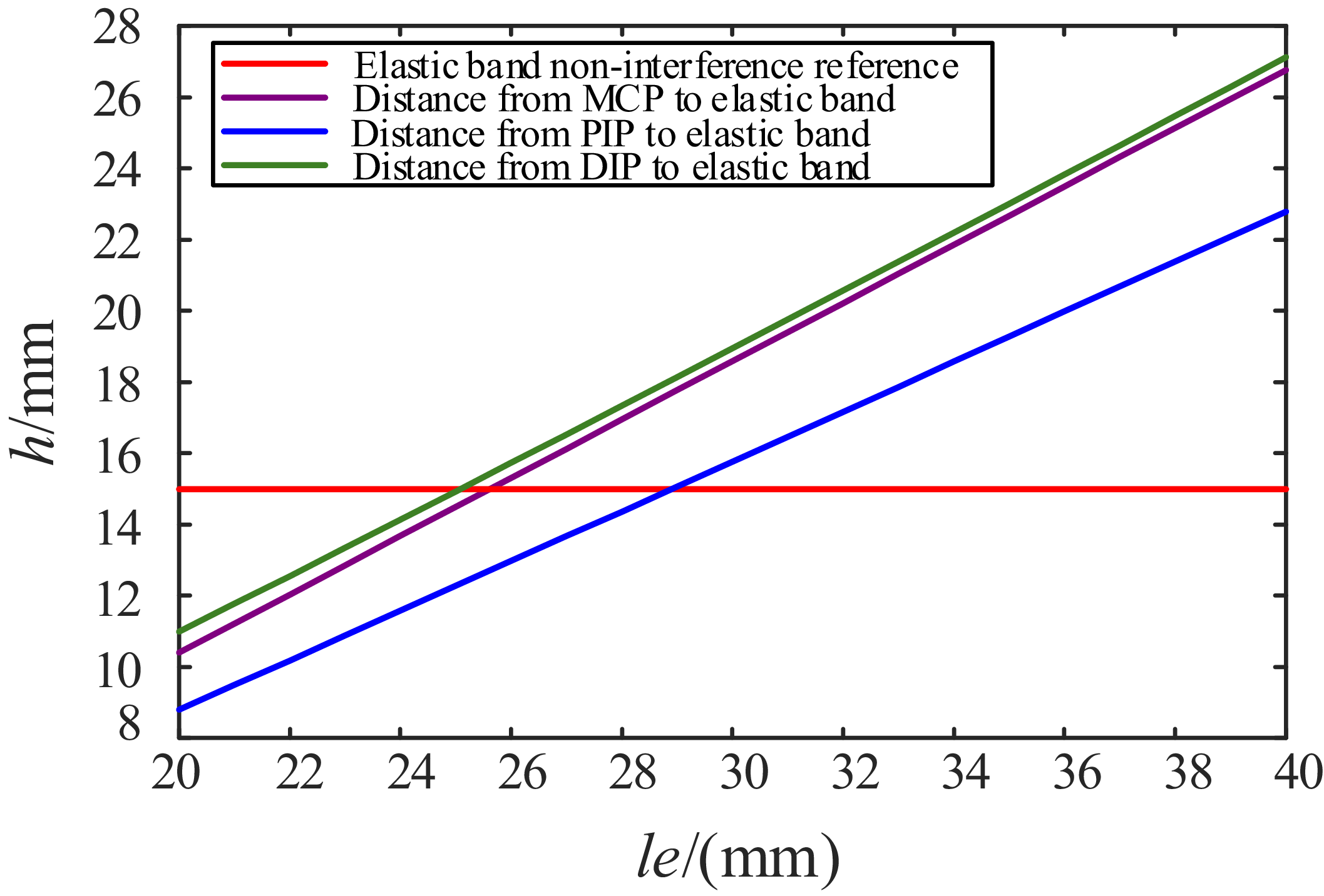
In Figure 14, h is the distance between the finger joint and the elastic band, and le is the distance of the elastic band from the fingers. The le size that allows the elastic cord and the leaf spring to not interfere is a minimum of about 29 mm.
Dimensional optimization result diagram optimization diagram.

The elastic force generated in the bending process of the elastic band is converted into a moment of force on the knuckle of the hand, which is equivalent to a force perpendicular to the fingertip.
 \begin{equation} F_{e}=k\left| \begin{array}{l} {\unicode[Arial]{x0394}} \end{array}\right| \frac{L_{|{o_{1}}-{e_{4}}{e_{5}}|}}{a_{1}+a_{2}+a_{3}} \end{equation}
 \begin{equation} \left| \begin{array}{l} {\unicode[Arial]{x0394}} \end{array}\right| =\left| \begin{array}{l} e_{0}e_{1} \end{array}\right| +\left| \begin{array}{l} e_{2}e_{3} \end{array}\right| +\left| \begin{array}{l} e_{4}e_{5} \end{array}\right| -\left(a_{1}+a_{2}+a_{3}+l_{0}-\frac{u_{0}}{2}-u_{1}-u_{2}-u_{3}\right) \end{equation}
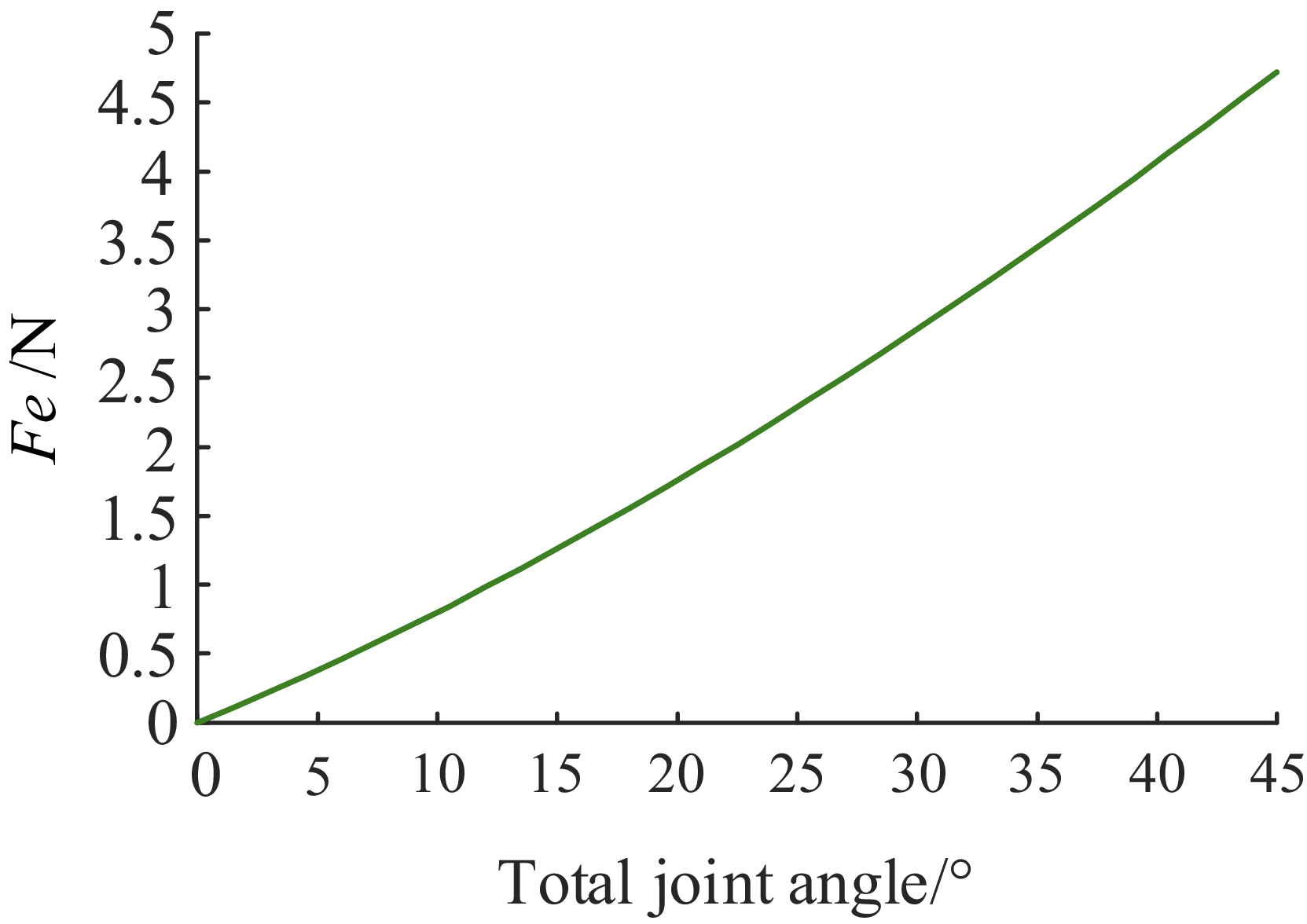
The simulation analysis results are as in Figure 15, it can be obtained that under the dual action of the leaf spring and the elastic band, when the exoskeleton is bent at a maximum angle of 15° in the initial state, it can ensure that the fingertips can overcome the contracture force of about 1.7 N. This resistance can ensure that the palms of general late-stage stroke recovery patients are in an open state.
Simulation of the ability to overcome contracture forces.

3.4. Exoskeleton cable tension analysis
In the process of the empty grip mode, the cable only needs to overcome the resistance torque generated by the deformation of the spring on the finger joints. Assuming that the output tension of the motor on the cable is T out , and τ d , τ p, and τ m are used to represent the torque on the DIP, PIP, and MCP joints, respectively, the torque generated by the cable on each joint of the human finger is as follows.
 \begin{equation} \left\{\begin{array}{l} \tau _{d}=\left| T_{out}\right| \dfrac{P_{6}P_{5}}{P_{6}P_{5}}\times O_{3}P_{6}\\[12pt] \tau _{p}=\left| T_{out}\right| \dfrac{P_{6}P_{5}}{P_{6}P_{5}}\times O_{2}P_{6}+\left| T_{out}\right| \dfrac{P_{5}P_{6}}{P_{5}P_{6}}\times O_{2}P_{5}+\left| T_{out}\right| \dfrac{P_{4}P_{3}}{P_{4}P_{3}}\times O_{2}P_{4}\\[12pt] \tau _{m}=\left| T_{out}\right| \dfrac{P_{6}P_{5}}{P_{6}P_{5}}\times O_{1}P_{6}+\left| T_{out}\right| \dfrac{P_{5}P_{6}}{P_{5}P_{6}}\times O_{1}P_{5}+\left| T_{out}\right| \dfrac{P_{4}P_{3}}{P_{4}P_{3}}\times O_{1}P_{4}\\[12pt]\qquad\qquad +\left| T_{out}\right|\dfrac{P_{3}P_{4}}{P_{3}P_{4}}\times O_{1}P_{3}+\left| T_{out}\right| \dfrac{P_{2}P_{1}}{P_{2}P_{1}}\times O_{1}P_{2} \end{array}\right. \end{equation}
Three-stage elastic resistance torque:
 \begin{align} \left\{\begin{array}{l} \tau _{3}=\dfrac{2EI\theta _{3}^{2}}{\left(L_{3}+\theta _{3}d\right)^{2}\sin \theta _{3}}\cdot \left(a_{3}-u_{3}\right)+T_{k-{e_{5}}{e_{4}}}\times o_{3}e_{5} \\[12pt] \tau _{2}=\dfrac{2EI\theta _{2}^{2}}{\left(L_{2}+\theta _{2}d\right)^{2}\sin \theta _{2}}\cdot \dfrac{a_{2}-u_{2}}{2}+T_{k-{e_{3}}{e_{2}}}\times o_{2}e_{3}+T_{k-{e_{4}}{e_{5}}}\times o_{2}e_{4}+T_{k-{e_{5}}{e_{4}}}\times o_{2}e_{5} \\[12pt] \tau _{1}=\dfrac{2EI\theta _{1}^{2}}{\left(L_{1}+\theta _{1}d\right)^{2}\sin \theta _{1}}\cdot \dfrac{a_{1}-u_{1}}{2}+T_{k-{e_{1}}{e_{0}}} \times o_{1}e_{1}+T_{k-{e_{2}}{e_{3}}} \times o_{1}e_{2} +T_{k-{e_{3}}{e_{2}}}\times o_{1}e_{3}\\[12pt]\qquad +T_{k-{e_{4}}{e_{5}}}\times o_{1}e_{4}+T_{k-{e_{3}}{e_{4}}}\times o_{1}e_{5} \end{array}\right. \end{align}
 \begin{equation} \tau _{m}=-\tau _{1} \quad \tau _{p}=-\tau _{2} \quad \tau _{d}=-\tau _{3} \end{equation}
 \begin{equation} \begin{array}{l} O_{1}=\left[\begin{array}{l@{\quad}l@{\quad}l} 0 & 0 & 0 \end{array}\right]^{T}\\[3pt] O_{2}=\left[a_{1}\cos \theta _{1} \quad a_{1}\sin \theta _{1} \quad 0\right]^{T}\\[3pt] O_{3}=\left[\left(a_{1}+a_{2}\right)\cos \theta _{1} \quad \left(a_{1}+a_{2}\right)\sin \theta _{1} \quad 0\right]^{T} \end{array}\end{equation}
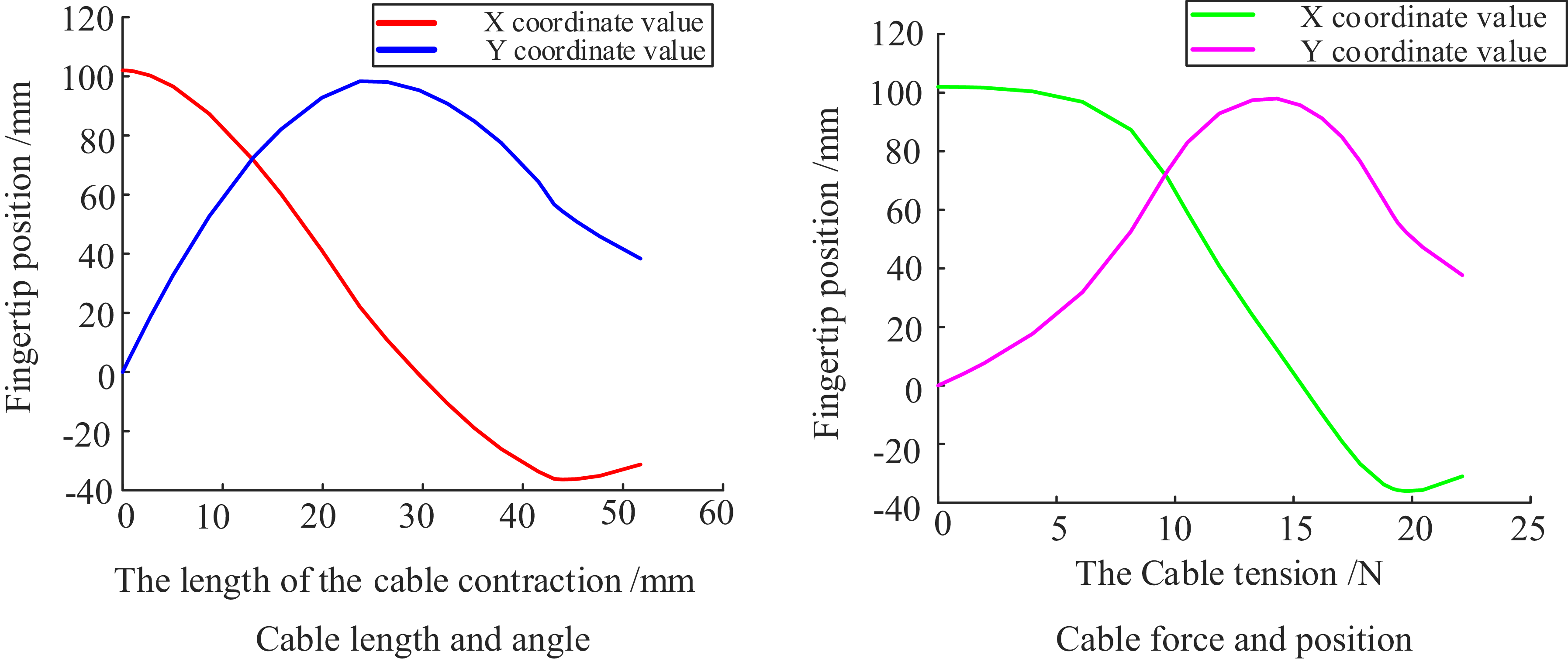
Use MATLAB to find the solution that meets the equation and draw a curve showing the relationship between the cable length and the fingertip coordinates as in Figure 16.
Force and position simulation results.

4. Experimental prototype testing and evaluation
4.1. Prototype testing
Figure 17 shows the test platform for the force of fingertip contracture that can be overcome by the exoskeleton. A single-finger model was made for testing. An angle reference line was drawn at intervals of 15°, and the force was measured by pulling the fingertips of the finger module to the corresponding position with a dynamometer. The results showed that the exoskeleton has a certain ability to resist the contracture force of the fingers.
Maximum constriction force test.

In order to reduce the weight of the wearable part, the finger bone block parts are all made by 3D printing, and nylon wire and sleeves are used for transmission. The prototype made based on the palm sleeve is shown in the figure. At the same time, in order to verify the feasibility of the designed exoskeleton, a prosthetic hand was made according to the size of adult fingers for a wearing test. The MCP joint of the prosthetic hand was designed as a ball joint, and the other joints were all revolute joints. At the same time, in order to simulate the characteristics of finger skin, a silicone finger sleeve was put on the printed finger block, and the prosthetic hand model made was shown in Figure 18.
Prototype and dummy hand-wearing model.

The experimental results show that the exoskeleton fingers can resist a certain amount of contracture force. When a tensile force is applied at the fingertips, the finger module bends, and when a force of 1.7N is applied, the angle of rotation is about 15°. When a force of 3.7 N is applied, the finger module stabilizes at an angle of rotation of about 30°, which is consistent with the theoretical analysis. It shows that the exoskeleton can still keep the fingers unfolded when stroke patients with mild finger contracture are afraid to wear it.
In order to verify the applicability of the designed exoskeleton hand for good life movement ability, this paper conducts a physical prototype control experiment on the exoskeleton rehabilitation manipulator. In order to verify that the exoskeleton has a certain grasping ability, the prosthetic hand is worn on the exoskeleton and driven, and the empty grip experiment and the grasping experiment are carried out, respectively. The experimental setup operated such that a predefined control signal prompted each exoskeleton finger module to perform a three-phase movement sequence:
-
(1) During the flexion phase, tension applied to the flexible cable caused the exoskeleton finger to bend, achieving finger flexion.
-
(2) In the maintenance phase, the cable length remained fixed, maintaining a constant tension to hold the finger in a flexed posture.
-
(3) For the extension phase, the cable tension was gradually released, allowing the finger to extend back to its initial position.
As shown in Figure 19, grasping tests were performed on objects of different shapes, including spheres, cylinders, cuboids, and irregular objects. Covering common grip forms in daily life. The experimental procedure evaluates common daily-life grasping postures. The program is initiated, and an object is manually positioned for the prosthetic hand to grasp. The hand then closes as its fingers gradually bend under the contraction of the soft rope. Once the fingers reach a suitable position, the object is released. A successful grasp is recorded if the object remains held for ten seconds; otherwise, the attempt is considered a failure. Each object underwent fifty grasping trials.
Prototype gripping ability test.

The experiment verifies that the designed exoskeleton has a large bending angle in the empty grip mode, which can meet the rehabilitation needs of patients. In the exoskeleton grasping test, the results (Figure 20) show that the device successfully grasped objects of various geometries and sizes. The success rate reached 100% for spherical, cylindrical, and irregularly shaped objects, while rectangular prisms were grasped with 94% success. Analysis of the rectangular prism trials reveals a small amplitude in the standard deviation curve, indicating high stability in the grasping performance. Furthermore, the narrow confidence interval and high mean success rate, as seen in the corresponding green curve, confirm that the estimated success rate for rectangular prisms is both accurate and reliable. The exoskeleton therefore achieved a high overall grasping success rate, and the experimental outcomes exhibit strong reliability. These results validate the rationality and dependability of the exoskeleton design, confirming that it meets the functional demands of daily living activities.
Analysis of the success rate of grasping objects of different shapes.

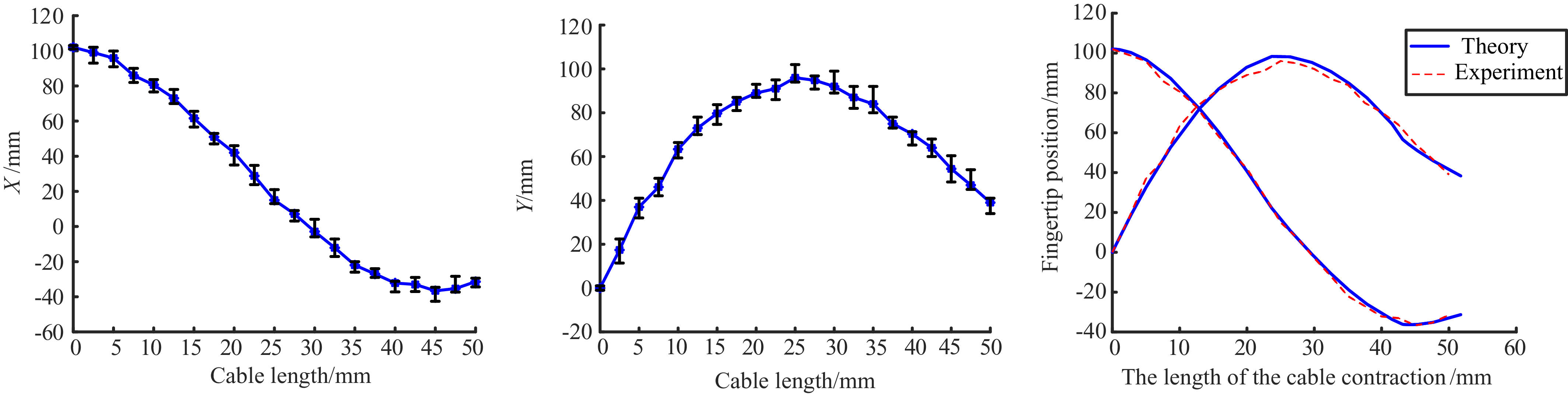
To verify the kinematic relationship of the exoskeleton, a fingertip coordinate measurement platform as shown in Figure 21 was built. Due to the thickness between the fingers of the exoskeleton, the length of the finger module after wearing the exoskeleton is longer. In order to match the length of the theoretical analysis, the fingertip of the finger module is taken as the measured fingertip coordinate instead of the exoskeleton fingertip. Record the fingertip coordinates at different positions and the corresponding cable length contraction, and draw the experimental result curve. Figure 22 shows the experimental results. There is a deviation between the experimental results and the theoretical curve. This is because the exoskeleton and the finger module have slippage and small-size separation during the movement, which affects the joint angle and causes a certain deviation in the fingertip position. But overall, it is consistent with the theoretical analysis and conforms to the kinematic theory modeling.
Single fingertip coordinate experimental device.

Experimental curves of multiple measurements of fingertip position.

4.2. Evaluation of prototype performance
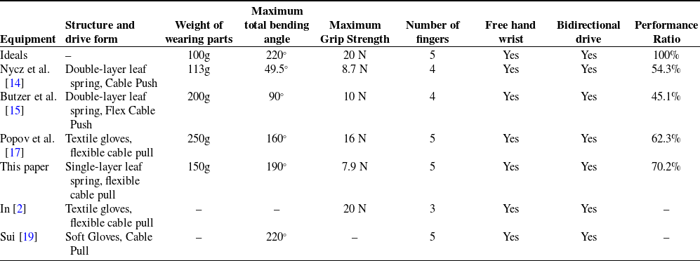
Table III is a summary of exoskeleton gloves used for hand rehabilitation and assistance in the last few years; the exoskeletons evaluated are those for which the relevant parameters were available in the original article, and those for which the relevant parameters could not be obtained are not evaluated. The following graphs show a comparison of these devices. The six axes in each figure are the six characteristics of the devices summarized in Table III, which are hand-wearing part weight, maximum finger bending angle, maximum fingertip force, assistive hand index, having a free wrist, and bi-directional actuation, which are scaled from a value of 20 corresponding to the inner hexagonal region of the grid to a value of 100. where the bi-directional actuation and having a free wrist are binary and have a value of either 2 or 10. Weight of the wearing part. Figure 23 shows the measurement results of the maximum fingertip force.
Evaluation of multiple exoskeleton performance parameters.

For the exoskeleton under ideal conditions, the following parameters were set: the weight was the weight of a single normal glove, which was set to 100g; the maximum fingertip force was 20 N; and the maximum bending angle was the maximum bending angle of the fingers when not wearing any device. For the wearable portion of the weight, G/100 was used as the weight, which was deflated between 20 and 100 according to the formula W = 10/e x based on the results obtained, so that the maximum weight corresponded to a value of 20 and the zero weight corresponded to a value of 100. where x denotes the weight in order to better reflect the difference between the weights close to zero.
Maximum fingertip force measurement.

Exoskeleton performance evaluation results.

The force scales linearly between 20 and 100, with a score of 100 corresponding to 20 N. The maximum bending angle of the exoskeleton selected for evaluation will be scaled between 20 and 100. Assuming a 100% hexagonal area for the ideal system, the relative scores for each glove are shown in Table III. The exoskeleton hexagonal evaluation diagram with available drawing parameters is shown in Figure 24. The structure of the exoskeleton in Table III is shown in Figure 1.
5. Conclusion
In this paper, through the study of the anatomical structure of the hand, a new underdriven flexible rehabilitation exoskeleton is proposed based on a cable and a single-layer elastic leaf spring, which can realize the active flexion or extension of the fingers and has the advantages of better fit, lighter weight of the wearing part, and larger bending angle compared with the double-layer leaf spring. According to the physiological characteristics of the hand, the exoskeleton is reasonably arranged with cable-guided components according to the division of flexor muscle lines, which minimizes interference with the flexibility of the human hand. The motion model of the index finger module when wearing the exoskeleton was established, the motion space was solved, the mapping relationship between the rope length and the finger joints was established, the overall stiffness of the finger module was analyzed, and it was verified that the finger module was able to resist a large finger contracture force under the initial state through the testing experiments. The exoskeleton prototype was made and worn on the prosthetic hand model for testing. Through the measurement of grasping and fingertip force on different objects, it proved that the exoskeleton has a good bending angle and grasping ability, and it can realize the basic movement elements of the patients’ sports training and task training. Evaluation indicators were designed to evaluate a variety of exoskeletons, and the results showed that the exoskeleton in this paper has a significant advantage in a combination of aspects, covering 70.2% of the area of the ideal exoskeleton.
In the future, the structure of the exoskeleton hand will be further optimized to reduce the existing human–machine slip problem. At the same time, appropriate control strategies will be used to control the force and position of the hand exoskeleton more accurately, and electromyographic signals will be added for active control.
Author contribution
Yupeng Zou, Junhe Chen, and Guangxu Zhou conceived and designed the study. Kefei Wang and Minghan Jiang performed data collection. Jianheng Tang, Qiang Yu, and Pengyue Wang conducted the statistical analysis. The manuscript was written by Yupeng Zou, Junhe Chen, and Guangxu Zhou.
Financial support
This research was funded by the National Natural Science Foundation (grant number:51705534) and the Shandong Provincial Natural Science Foundation (grant number: ZR2020MF291).
Competing interests
The authors declare no conflicts of interest exist.
Ethical standards
“The authors assert that all procedures contributing to this work comply with the ethical standards of the relevant national and institutional committees on human experimentation and with the Helsinki Declaration of 1975, as revised in 2008,” and “the authors assert that all procedures contributing to this work comply with the ethical standards of the relevant national and institutional guides on the care and use of laboratory animals.”
Use of AI
The authors declare no use of AI exists.