
Introduction
Methods and materials used for nerve repair have limitations that stimulate research to design and characterize novel biomaterials. Specifically, these biomaterials should enhance the length of neurite extension by neurons and control the directionality of those extensions. The current solutions used for nerve regeneration are not successful in clinical settings because they do not provide guidance to control the directionality of neurite extension. As a consequence, incomplete axon regeneration ensues leading to aberrant tissue innervation often resulting in a loss of both motor and sensory functions.[Reference Hronik-Tupaj, Raja, Tang-Schomer, Omenetto and Kaplan1] In these cases, axons regenerating across conduits often disperse[Reference Diekmann and Fischer2] which results in inappropriate and inaccurate target reinnervations.[Reference Hronik-Tupaj, Raja, Tang-Schomer, Omenetto and Kaplan1,Reference Diekmann and Fischer2] Other in vitro studies have shown patterning capabilities by using surface cues to induce alignment or directional growth of cells, collectively referred to as “contact guidance”.[Reference Hoffman-Kim, Mitchel and Bellamkonda3,Reference Lim and Donahue4] Studies demonstrating versatile technology that can successfully deliver patterning and contact guidance while also providing electrical stimulation are severely lacking mainly due to the nature of the scaffold/ conduit material choice. The limitations imposed by the choice of material can be circumvented by the use of aerogels because aerogels can be used in vivo therefore, in vitro studies can be transferred to in vivo models, can support patterning to create contact guidance, and are tolerant to processing steps required to ultimately create an electrical interface with neurons.[Reference Lynch, Skalli and Sabri5]
Aerogels are a class of mesoporous materials. They represent attractive biomaterials because their tunable chemical, physical, bulk, and surface properties are tunable. This makes aerogels excellent candidates for in vitro and in vivo applications as evidenced by the body of recently published work.[Reference Lynch, Skalli and Sabri5–Reference Sabri, Gerth, Tamula, Phung, Lynch and Boughter12] In particular, aerogels have shown great promise as a scaffold for nerve guidance and regeneration in the presence and absence of electrical stimuli.[Reference Lynch, Skalli and Sabri5,Reference Lynch, Skalli and Sabri6,Reference Rodriguez Sala, Lynch, Chandrasekaran, Skalli, Worsley and Sabri10,Reference Hadley, Hirschman, Morshed and Sabri11] PC-12 cells grown on polyurea crosslinked silica aerogels and carbon-based aerogels regenerated at a faster rate when compared to the behavior of the neurons on smooth surfaces such as polystyrene Petri dishes[Reference Lynch, Skalli and Sabri5,Reference Lynch, Skalli and Sabri6,Reference Rodriguez Sala, Lynch, Chandrasekaran, Skalli, Worsley and Sabri10] which has been attributed to the unique surface and bulk properties of aerogels. However, in these studies, no patterning was attempted and is the focus of the study presented here.
Many recent works have shown that it is possible to align liquid crystal (LC) molecules into non-uniform spatially orientated patterns. Several applications and novel LC devices have sprung from this property of LC, including beam steering[Reference Beeckman, Neyts and Vanbrabant13,Reference McManamon, Bos, Escuti, Heikenfeld, Serati, Xie and Watson14] q-plates,[Reference Chen, Ji, Wei, Hu, Chigrinov and Lu15,Reference Wei, Hu, Ming, Xu, Rubin, Wang, Chigrinov and Lu16] geometric phase-wave plates,[Reference Hronik-Tupaj, Raja, Tang-Schomer, Omenetto and Kaplan1,Reference Diekmann and Fischer2] programable origamis,[Reference Iqbal and Samiullah17,Reference de Haan, Sánchez-Somolinos, Bastiaansen, Schenning and Broer18] predesigned microfluidic electrokinetic flows in LCs, controlled particles positioning and assembly,[Reference Peng, Turiv, Zhang, Guo, Shiyanovskii, Wei, de Pablo and Lavrentovich19] and active matter command.[Reference Peng, Guo, Turiv, Jiang, Wei and Lavrentovich20] A recently proposed approach for surface photo-patterning that is based on plasmonic photomasks has extended the photo-alignment techniques to aqueous LC systems, which is biocompatible and suitable for interfacing with cells (e.g., bacteria) and peptide amphiphiles.[Reference Peng, Turiv, Guo, Wei and Lavrentovich21,Reference van der Asdonk, Hendrikse, Fernandez-Castano Romera, Voerman, Ramakers, Löwik, Sijbesma and Kouwer22] The proposed technique is better suited for design and patterning of biomaterials when compared to other patterning techniques currently used such as lithography-based techniques. Plasmonic photo-patterning enables to create controlled and specific spatial alignment of aqueous LCs. This process eliminates repeated exposures to light beams with differently polarized waves and does not involve the use of surfactants. The use of plasmonic metamasks to control light polarization enables us to avoid multiple exposures of the LC[Reference Peng, Guo, Conklin, Viñals, Shiyanovskii, Wei and Lavrentovich23], unlike standard photomasks that solely control transmitted light intensity.[Reference Gao, Cheng, Bhowmik and Bos24,Reference Niv, Biener, Kleiner and Hasman25]
This technique has been very successful at creating LC patterns precisely guiding and manipulating the flow trajectory of bacterial cells. When bacteria are dispersed in an LC pattern, it imposes the (i) geometry of cell motion trajectories, (ii) the polarity of motility, and (iii) the spatial distribution of the concentration of bacterial cells.[Reference Peng, Turiv, Guo, Wei and Lavrentovich21] This demonstrates that a patterned soft biomaterial representing an anisotropic environment has the potential to represent a new dynamic biomaterial system. Here, the authors report on the first study that uses a plasmonic photo-patterning technique to create a new generation of biomaterials containing preformed patterns on aerogels for precise contact guidance of neurons. Results show the successful transfer of pattern onto aerogel and glass (control) substrates, as well as the evidence of stability of the transferred pattern. Some evidence of cell alignment on patterned substrates has also been presented.
Materials and methods
Preparation of aerogel scaffold
Polyurea crosslinked silica aerogel monoliths were synthesized in accordance with previously described methods.[Reference Lynch, Skalli and Sabri5,Reference Lynch, Skalli and Sabri6] In brief, 8.75 × 10⁻³ L methanol was added to 1.5 × 10⁻³ L deionized (DI) water. To this mixture, 3.85 × 10⁻³ L tetramethyl orthosilicate (TMOS) (Sigma-Aldrich, St. Louis, MO, USA) and 0.25 × 10⁻³ L (3-aminopropyl) triethoxysilane (APTES) (Sigma-Aldrich, St. Louis, MO, USA) were added simultaneously. Next, the mixture was stirred for 15 s and poured into custom-designed molds of 5 × 10⁻² m in diameter. This final mixture was then allowed to cure. When cured, the samples were washed with methanol (Sigma-Aldrich, St. Louis, MO, USA) and submersed for 4 days in acetonitrile. Cross-linking of the material was achieved by transferring it to a 33 g Desmodur N3200 (Bayer Material Science, Leverkusen, Germany)/94 mL acetonitrile (Sigma-Aldrich, St. Louis, MO, USA) mixture in which it remained for 24 h as previously detailed.[Reference Lynch, Skalli and Sabri5,Reference Lynch, Skalli and Sabri6] Samples were then dried by critical point drying and optically inspected for quality assurance. The final samples were sectioned into 5 × 5 mm2 coupons prior to the plasmonic photo-patterning stage. Glass slides were also cleaned and sectioned into 1 cm2 segments to serve as a control for the patterning stage.
Plasmonic photo-patterning of glass and aerogel
To create the precise patterns on the aerogels and the glass (control) substrates, plasmonic photo-patterning technique was adopted. To accomplish this, the photosensitive azodye material SD1 (Sigma-Aldrich, St. Louis, MO, USA) was used without further purification and mixed with n,n-dimethylformamide solvent at a final concentration of 0.3% w/v. The SD1 solution was spin-coated on cleaned aerogel discs for 30 s at 3000 rpm. The aerogel disks were subsequently baked for 30 min at 90°C and then exposed for 5 min in the photo-patterning exposure system with a photonic meta-mask.[Reference Peng, Guo, Turiv, Jiang, Wei and Lavrentovich20] The photonic masks containing the desired pattern were custom-made in-house of aluminum films of 150 × 10−9 m thickness, which were perforated with rectangular nanoslits, each of a length 220 × 10−9 m and width 100 × 10−9 m. An unpolarized light beam passing through the photomask slits becomes linearly polarized with the polarization vector perpendicular to the long side of the slit. The orientation of slits differs between points in the mask. Due to this, the light polarization also varies in space such that it achieves the desired director alignment. Irradiation of the photosensitive substrate through the photomask with a predesigned pattern causes the locally polarized beam to realign the photosensitive molecules of SD1 perpendicularly to the incident polarized light. This results in the imprinting of the polarization pattern of light onto the photosensitive layer used to align the liquid crystals.
Since SD1 is partly water soluble, an additional layer of polymerizable material is added separating the SD1 layer from the water. Toluene and monomer RM257 (EM Industry, NJ, USA ) were mixed with the photoinitiator Irgacure 651 at a final concentration of 10% w/v (Ciba, Inc., Base, Switzerland) at the concentration 5 wt% of RM257. This solution was spin-coated onto the SD1 aerogel disks at 3000 rpm for 30 s and then baked at 55°C for 5 min in order to evaporate the solvent. Next, photo-polymerization was induced for 30 min with unpolarized ultraviolet (UV) light at an intensity of 1.4 mW/cm2. This liquid crystalline polymer pattern is expected to replicate the pattern of SD1 alignment beneath it. To pattern the sectioned and cleaned glass slides, the same steps were repeated with exact conditions. Aerogel disks and glass slides containing the pattern were then treated for collagen coating and cell culture.
Collagen coating
Crosslinked silica aerogels and sectioned glass slides were sterilized for 30 min under UV light (λ = 420 × 10−9 m) and coated with collagen as described in detail previously.[Reference Lynch, Skalli and Sabri5,Reference Lynch, Skalli and Sabri6] Briefly, rat tail type I collagen (Invitrogen, Carlsbad, CA, USA) was diluted in 20 mM acetic acid to a final concentration of 0.05 mg/mL. The collagen solution was then deposited onto the aerogel or glass substrate to reach a final protein density of 4 µg/cm2. Samples coated with the collagen solution were then stored for 1 h at room temperature in a sterile biosafety cabinet. After 1 h had elapsed, the excess collagen solution was carefully removed with a vacuum line. The samples were then rinsed with serum-free RPMI 1640 with great care in order to prevent disturbance of the layered plasmonic photo-patterning. Earlier samples showed folding of the polymer film, which was avoided in later trials by careful and gentle washing. The substrates were then ready for the cell culture stage.
PC-12 cell culture
PC-12 pheochromocytoma cells [American Type Culture Collection (ATCC), Manassas, VA, USA] were grown in RPMI 1640 medium supplemented with GlutaMax, HEPES buffer, 5% fetal bovine serum, 10% horse serum, 100 µg/mL penicillin, and 0.1 mg/mL streptomycin. Before each experiment, PC-12 cells were primed to achieve neural differentiation as has been described in detail previously.[Reference Lynch, Skalli and Sabri5,Reference Lynch, Skalli and Sabri6] Every 2 days, the medium was replaced with fresh low serum medium supplemented with NGF. Cells were harvested from the dish after 8 days in culture and frozen in liquid nitrogen until used for plating on glass substrates or aerogels.[Reference Hronik-Tupaj, Raja, Tang-Schomer, Omenetto and Kaplan1] Each experiment consisted of PC-12 cells cultured in the substrate for 24 h with NGF and then fixed, imaged, and analyzed. Both glass and aerogel substrates without plasmonic photo-patterning were also prepared for cell culture and served as the control for this investigation.
Fixing and imaging
The fixing protocol used in this study is as follows: first samples were fixed for 2 h in 2.5% glutaraldehyde (Tousimis, Rockville, MD, USA) in 0.1 M sodium cacodylate buffer. Next, samples were washed with 0.1 M sodium cacodylate buffer two times, each for a duration of 10 min. Samples were then post-fixed for 1 h with an aqueous solution of 1% osmium tetroxide (Electron Microscopy Sciences, Hatfield, PA, USA). This was followed by 2× 10 min washes in 0.1 M sodium cacodylate buffer. The dehydration stage involved a series of 10 min each washes in 10%, 30%, 50%, 70%, 90%, and 100% ethanol. Finally, the substrates were air dried and sputter coated with a 10 × 10−9 m gold/palladium film. Scanning electron microscopy was performed on a Phenom desktop Scanning Electron Microscope (SEM) (Phenom-World, Eindhoven, Netherlands) to analyze the neurite length and orientation of the cells. It was operated at 10 keV using the backscatter electron detector (BSD) in full mode.
High-resolution 3D profile images of the substrates with/without cells were obtained by means of a 3D Profilometer (Filmetrics Inc., San Diego, CA, USA) using white light interferometry. Samples were prepared for profilometry by first sputter-coating them with a 10 nm AuPd layer. Image acquisition and analysis were performed using the Profilm3D software.
Measurements of neurite
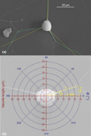
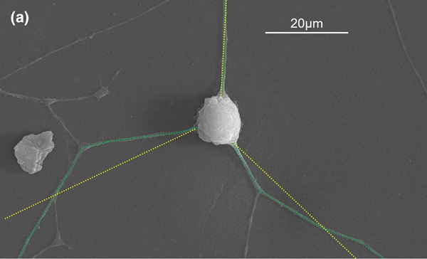
In this investigation, the criteria used for neurite selection were performed in accordance with the method described previously.[Reference Rodriguez Sala, Lynch, Chandrasekaran, Skalli, Worsley and Sabri10] Neurite lengths and neurite orientations were measured with the NIH ImageJ open-access software. The length measurement tool was calibrated by taking advantage of the machine-generated scale-bar of SEM images. Neurites were treated as vectors and accordingly their length was measured by tracing a series of straight-line segments with the line segment tool [Fig. 1(a), green and yellow traces]. Neurites were defined as the longest cytoplasmic extensions directly originating from the cell body. Short branches stemming off these extensions were not considered for measurement. Only the longest branch of branched neurite was considered for length measurement. To measure neurite orientation, the cell body was treated as the origin point of a polar plot [Fig. 1(b)] and the neurite orientation was measured with an angle from 0° to 360° using the straight-line tool [Fig. 1(b), polar plot with orientation]. For the substrate with a linear plasmonic photo-pattern, the analysis was carried with the pattern in the orientation of 0° and 180°. The overall orientation of the neurites was determined using the following vector projection analysis:
 $$x = \displaystyle{1 \over N}\mathop \sum \limits_{i = 1}^N L_i\; \cos \theta _i\; \quad \quad \; y = \displaystyle{1 \over N}\mathop \sum \limits_{i = 1}^N L_i\; \sin \theta _i$$
where N is the total number of neurites measured, L is the individual neurite length, and θ is the individual neurite angle with respect to the horizontal axis.[Reference Rodriguez Sala, Lynch, Chandrasekaran, Skalli, Worsley and Sabri10]
Neurite measurement and orientation: (a) green trace superposed on the neurites represents the measurement of the neurite length while yellow trace shows the overall orientation of that neurite. (b) Polar and Cartesian coordinates superimposed on an SEM image of a cell demonstrating the measurement of each neurite orientation.

Results and discussion
Successful transfer of pattern onto aerogel
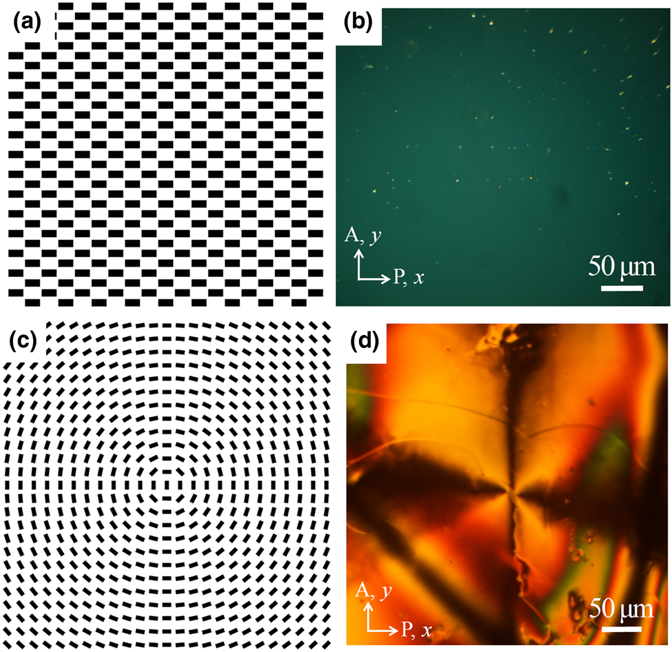
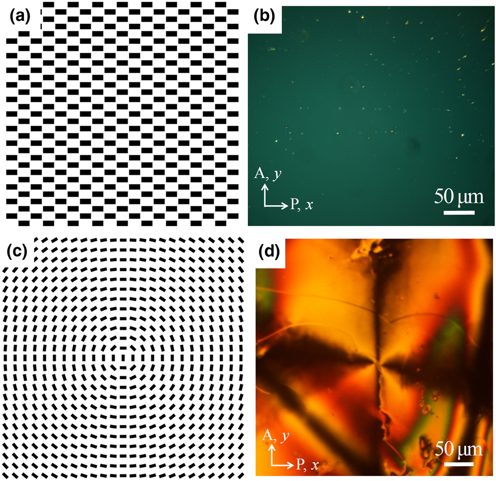
A new approach to successfully apply plasmonic photo-patterning to aerogels is described and shown with two different geometries of patterns applied to polyurea crosslinked silica aerogel. When planar liquid crystalline polymer pattern along X-axis is imprinted on the glass substrate [Fig. 2(a)], this pattern shows uniform dark texture between crossed polarizers as can be seen in Fig. 2(b). We have demonstrated that we can successfully transfer the patterned liquid crystal polymer to the aerogel also. Circular alignment of the liquid crystalline polymer with a length scale around 500 × 10−6 m is photo-patterned on the aerogel surface for further neuron guidance as shown in Figs. 2(c) and 2(d). The stability and reproducibility of the transferred pattern were evaluated periodically and proved to be well adhered to the substrate. Repeated liquid exchanges during the cell culture steps did not adversely affect the pattern layer. This was confirmed by optical inspection under the polarizing optical microscopy.
Plasmonic photo-patterning: (a) schematic diagram of the uniform linear alignment along horizontal X-axis, (b) uniform alignment of liquid crystal polymer on a glass substrate, (c) schematic diagram of a circular alignment, and (d) circular alignment pattern of liquid crystalline polymer transferred to the aerogel substrate.
Neuron response to patterned substrates
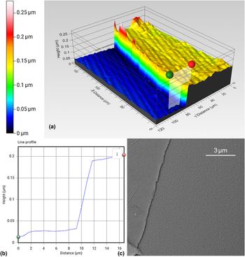
Successful culture of PC-12 cells onto aerogel substrates and glass that had undergone plasmonic photo-patterning was accomplished. After 1 day (24 h) of cell culture, cells showed neurite outgrowth indicating that collagen-coated and plasmonic photo-patterned aerogels are well suited to serve as scaffolds for neuronal growth and orientation. The uniformity of the polymer layer on the aerogel and the glass substrate was evaluated at different locations both by means of SEM and profilometry. Representative profiles are shown in Fig. 3. Figure 3(a) shows an image of the boundary between the pattern and the substrate over approximately a 200 × 10−6 μm range. The height of the boundary was measured at different points and a representative measurement is shown in Fig. 3(b) where a “step height” measurement is taken at the location indicated by the green and red markers of Fig. 3(a). Furthermore, the SEM analysis of the boundaries concurs with the uniformity and continuity results inferred from the profilometry images [Fig. 3(c)].
Pattern–substrate boundary: (a) profilometry and microscopy images of the boundary between the pattern and the substrate showing continuity and uniformity of the polymer layer. (b) A step height representative scan showing an approximate layer thickness. (c) SEM image of a representative region showing the boundary between the pattern and the aerogel substrate.

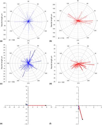
When the response of the PC-12 cells to patterned and non-patterned glass and aerogel substrates was compared, it was determined that the cells do, in fact, follow some degree of alignment with the pattern underneath, as shown in Fig. 4. Initially, the response of PC-12 cells to a glass or aerogel substrate lacking any patterning was evaluated. Results show that the distribution of neurites, as expected, does not have a preference in orientation [Figs. 4(a) and 4(e), and blue traces in 4(e) and 4(f)]. However, PC-12 cells grown on patterned glass and aerogel substrates do, in fact, show a preferred direction of alignment which in each case is consistent with the pattern on the substrates [Figs. 4(b) and 4(d), and red traces in 4(e) and 4(f)].
Response of PC-12 cells to patterned substrates: Polar plot of neurites on glass (a) in the absence and (b) presence of a pattern. Polar plot of neurite length and orientation on aerogel (c) in the absence and (d) presence of a pattern. Cartesian representation of the polar plots for (e) glass substrate and (f) aerogel substrate where blue represents no patterning and red represents a response to a patterned substrate in each case.

Summary and conclusion
A wealth of evidence supports the notion that the topographic features of the substrate at the nanoscale level profoundly impact various cellular properties. Because PC-12 cells are anchorage-dependent, they differentiate only after successful anchoring to the substrate. In light of this, we can conclude from the results of our study that both glass and polyurea crosslinked silica aerogel substrates previously layered with plasmonic photo-patterning and collagen provide the necessary conditions for initial anchoring of PC-12 cells.
Acknowledgments
F.S. would like to thank the FedEx Institute of Technology for partial financial support. C.P. would like to thank the University of Memphis start-up funds.