1. Introduction
Inspired by the behavior of animals in nature [Reference Fan, Thakker and Bartlett1, Reference Guo, Zhang, Guo, Li and Yang2], such as birds and turtles, researchers have realized that robots that possess multi-modal locomotion can offset the shortcomings of uni-modal robots. For instance, they can take different locomotion modes for different requirements to make tasks completed more quickly and efficiently. In special robot applications, multi-modal mobility robots are stealing researchers’ attention away and show great potential for development. In all multi-modal robots, terrestrial/aerial hybrid robots are most concerned because of their flying and driving abilities. To be more specific, the terrestrial/aerial robot can use flight mode to traverse obstacles such as steps, deep pits, and fences that are difficult to pass smoothly, enabling fast maneuvers and reconnaissance over a wide range of space; it can also use ground movement mode to increase its working endurance and achieve detailed search on the ground. Therefore, our research focuses on developing a novel terrestrial/aerial hybrid robot to realize dual-modal mobility and achieve energy saving in applications.
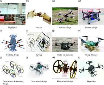
Recently, various approaches have been proposed to design a terrestrial/aerial hybrid robot [Reference Araki, Strang, Pohorecky, Qiu, Naegeli and Rus3–Reference Zhu, Guo, Li and Wang7]. Some researchers added a flexible film to a quadruped robot to realize its flying ability, called Flying Rat [Reference Shin, Park and Park8]. Daler L designed the DALER [Reference Daler, Lecoeur, Bernadette and Floreano9], an adaptive morphological robot that achieves ground movement by rotating its wings. However, it relies on manual assistance for take-off and is short of applicability. Other researchers [Reference Morton and Papanikolopoulos10] proposed a two-wheel rotor cylinder structure, with the four rotors folded into a cylindrical fuselage when rolling on the ground to avoid accidental collisions. All the hybrid robots mentioned above belong to a concept of reconfigurable robots which can alter their structure to adapt to different locomotion modes, and this idea has been applied to plenty of designs of terrestrial/aerial robot [Reference David and Zarrouk11–Reference Zhou, Xu, Xu, Chang, Wang and Chen15]. Nevertheless, these reconfigurable mechanisms are too complex and space occupied, which squeezes the room for deploying sensors and controllers and restricts the robot from being more autonomous.
Another efficient way for hybrid robots to achieve flying ability is to build a quadrotor with a ground mobility structure to lighten the weight or simplify the mechanism. Based on the idea, Kalantari A designed a cylindrical envelope quadrotor (HyTAQ) [Reference Kalantari and Spenko16], which puts a quadrotor in a cylindrical cage to achieve flying and driving modes. Dudley CJ designed a spherical rolling flying robot [Reference Dudley, Woods and Leang17], where the robot’s ground movement can effectively traverse narrow paths and pipes. Those designs reduce the complicity and size of the hybrid robot. However, they also suffer from weak load capacity and the inability to carry sensors for awareness, limiting the development of autonomous capabilities. Refs. [Reference Premachandra, Otsuka, Gohara, Ninomiya and Kato6] and [Reference Pan, Jiang, Zhang, Xu and Gao18] combines a quadrotor with four/one independent wheels to achieve dual-modal mobility while their ground locomotion ability is limited. Currently, the design of terrestrial/aerial hybrid robots is mainly based on the idea of multi-rotors combining with mobile chassis, which include Ackerman structure, dual-wheel, rolling cage, and other untraditional wheels [Reference Kalantari and Spenko19–Reference Zhang, Wu and Zhang25]. These design schemes reserve the space for sensors and controllers, and their dual-modal locomotion can be switched without assistance. Several examples of hybrid robots [Reference Fan, Thakker and Bartlett1, Reference Kalantari, Touma, Kim, Jitosho, Strickland, Lopez and Agha-Mohammadi5, Reference Premachandra, Otsuka, Gohara, Ninomiya and Kato6, Reference Shin, Park and Park8–Reference Morton and Papanikolopoulos10, Reference Kalantari and Spenko16, Reference Pan, Jiang, Zhang, Xu and Gao18, Reference Mulgaonkar, Araki and Koh26–Reference Wang, Shi, Wang, Wang, Feng and You29] with dual-modal locomotion capabilities are shown in Fig. 1.
Examples of some terrestrial/aerial hybrid robots.

In this paper, we developed an innovative terrestrial/aerial hybrid robot system named autonomous quadrotor tilting hybrid robot (AQT-HR), whose driving force is offered by the quadrotor, and the force direction can be altered through a tilting mechanism. In this way, we realize the hybrid robot’s terrestrial/aerial dual-modal mobility. Compared with the existing works, our contributions are considered in the following ways: (1) Developing an innovative terrestrial/aerial hybrid robot based on a lightweight, impact-absorbing, and compact structure design principle, and providing a design reference for the multi-modal robot area., (2) deriving the dynamics of dual-modal locomotion, including the ground movement dynamic model which is completely new, and introducing the models into the control algorithm to achieve stable indoor flying, and (3) realizing the robot’s autonomous mode switching, which is not achievable in the previous work [Reference Zhang, Guo, Ren, Zhu, Xu and Lu24], and the hybrid robot can achieve 72% energy saving efficiency based on the mode switching.
This paper is organized as follows. We first present the design concept of the hybrid robot in Section 2, including mechanical structure, hardware architecture, and manufacturing. Then, in Section 3, we build the hybrid robot’s dynamics model, including aerial flying and ground movement dynamics, and introduce the models to the motion control algorithm. After that, in Section 4, we present the conducted experiments to evaluate the robot’s capabilities and demonstrate that it can traverse the obstacles by switching locomotion mode autonomously and achieve energy efficiency. Finally, we conclude our work and make a future expectation in Section 5.
2. The design of the hybrid robot
2.1. Entire design of the AQT-HR
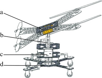
The AQT-HR is designed by considering lightweight, fast mode switching and autonomous movement requirements, which takes the hierarchical structure to avoid conflict among all parts. The robot model comprises the flight pattern, the tilting mechanism, the battery storage room, and the ground movement chassis, as shown in Fig. 2. The flight mode is deployed by making the quadrotor parallel to the ground, the ground movement mode is deployed by tilting the quadrotor and activating the dual-servo mechanism which is mounted on the chassis. The design concept includes three aspects: (1) realizing the dual-mode mobility using one single driving source, (2) reserving a sufficient room for sensor components and making the robot’s scale smaller, and (3) most of the robot’s elements can be installed and disassembled conveniently, and the entire mechanical structure remains solid and impact-resistant.
The entire structure of the AQT-HR. (a) Flight pattern, (b) tilting mechanism, (c) battery storage room, (d) ground movement chassis.

2.2. The design of the flight mode
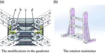
The flight mode is based on the structure of the quadrotor airframe and the tilting mechanism. Firstly, the airframe structure adopts a multi-hole cleat connection to allow for the mounting of the motors, eliminating the need for a shaft clamping device. In addition, the airframe reduces the weight by hollowing out in several places, meanwhile allowing more airflow underneath, reducing lift losses, and being more compact. Secondly, the quadrotor configuration has been modified to achieve the tilting function, as shown in Fig. 3a. Finally, depending on the tilting mechanism, the quadrotor can rotate in the pitch direction with the shaft as the rotation center. The key point of rotation design is to reasonably realize the axial and circumferential limits of the rotating parts. The axial limit ensures that the rotating parts will not slide around in the axis direction of the rotating shaft, while the circumferential limit provides coaxially between the rotating parts and the rotating shaft. In our design, the limit sleeve, the rotation maintainer, and the shaft retaining block are designed to prevent sliding.
The modifications in the quadrotor. (a) Shaft retaining block, (b) limit sleeve, (c) shaft, (d) rotation maintainer.

In order to ensure that the robot is impact-resistant during take-off and landing, the rotation maintainer needs to have high stiffness and strength. Therefore, a special design of the rotation maintainer is shown in Fig. 3b, which uses a double layer of beams and rounded corners to increase the structural stiffness in the horizontal direction, and two hollowed-out reinforcement bars in the vertical direction. The advantages of the design are that it strengthens the support frame against vertical impact and reduces the weight. In addition, the tilting servo motor is mounted at the bottom of the rotating maintainer. To ensure safety, the rotation maintainer’s finite element analysis simulation is conducted by using SolidWorks.
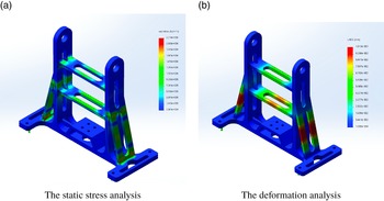
The analysis of the rotation maintainer.

The total weight of the robot is estimated to be 3 kg. Considering a safety factor, a static force of 40 N was applied to the structural element for simulation testing. The results are shown in Fig. 4a and b. Figure 4a shows the stress distribution in each part of the rotation maintainer after the force is applied, with a maximum value of 2.21
 $\times$
10
 $^{6}$
N/m
 $^{2}$
, which is much smaller than the material’s elastic modulus of 2
 $\times$
10
 $^{3}$
MPa. Figure 4b shows the deformation and displacement after the force is applied, with a maximum value of 0.1013 mm. As can be seen, there is not major deformation or structural fracture of the rotation maintainer occurred, which is in line with the design expectations.
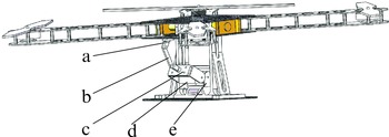
The flight pattern consists of the quadrotor configuration and the tilting mechanism, which converts the direction of the driving force, as shown in Fig. 5. The output torque is transmitted to the quadrotor configuration via the servo rod, the linkage, the fixer beneath the quadrotor and the shaft to achieve rotational angle control. The maximum forward tilt angle of the quadrotor is measured to be 37.5
 $^{\circ }$
, which indicates that 3/5 of the thrust force can be converted to ground locomotion driving force, improving the ability to move quickly on the ground.
The servo tilting mechanism. (a) Fixer beneath the quadrotor, (b) linkage, (c) servo rod, (d) servo, (e) servo support.

2.3. The design of the ground movement mode
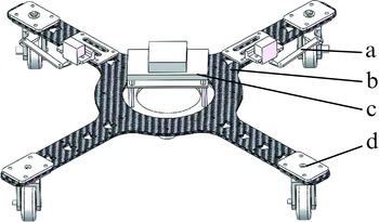
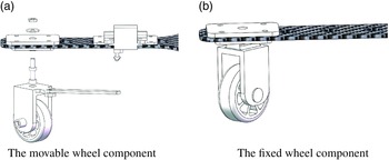
The configuration of the mobile chassis is shown in Fig. 6. The ground flexible movement is achieved through a dual-servo steering mechanism. The mobile chassis’s optimized design is X-shaped, with the main processor mounted at the center of gravity, and the four wheels symmetrically distributed. At the same time, the chassis is made of carbon fiber with multiple rounded corners and hollowed-out areas to lighten the weight. The chassis’ shape design and material selection allow the robot to reduce damage caused by unstable falls and offset some landing impacts. The four wheels of the chassis contain two movable wheel components and two fixed wheel components, with the front dual-servo steering mechanism achieving the robot’s ground turning capability, as shown in Fig. 7a. The movable wheel components are mirror symmetrically mounted on the front, with their support parts extending in a specific shape, which connects to the servo rods through linkage to realize the torque transfer from the servo to the movable wheels. The rear wheels are fixed directly to the rear side of the chassis to assist the ground movement. The structure is shown in Fig. 7b.
The ground movement chassis. (a) Dual-servo steering mechanism, (b) chassis plate, (c) main processor, (d) fixed wheel components.

Wheel components of the chassis.

2.4. The hardware architecture of the AQT-HR
The robot’s hardware architecture contains motors, sensors, control boards, and other electronic components. Among these, the thrust force generated by motors and blades is essential in achieving mobility and needs to be considered first. The static thrust calculation [Reference Chen30] of the propeller blades is shown as follows:
 \begin{equation} T_{s} = 1.283\times 10^{-12} \times \text{RPM}^{2} \times D^{4} \times \rho \times K_{t} \times K_{g} \end{equation}
 $T_s$
: static thrust generated by the propeller blades, N;
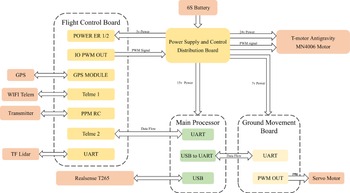
The electrical system of the AQT-HR.

The AQT-HR is an autonomous robot designed to fly and drive in various environments.

RPM: motor speed, rpm;
 $D$
: the diameter of the propeller blades, inches;
 $\rho$
: air density, taking the conventional value of 1.293 kg/m
 $^3$
 $K_t$
: static thrust coefficient, taking the conventional value of 0.73.
 $K_g$
: the acceleration of gravity, taking the conventional value of 9.82 m/s
 $^2$
T-motor 1555 blades and antigravity MN4006 motors are selected as the force generator. Each motor weighs 68 g and can provide a 21.6 N maximum thrust based on the manufacturer’s specification. According to Eq. (1), consider the expected total weight of the robot, which is 3.5 kg. We can calculate the maximum thrust of the hybrid robot will reach 86 N. This indicates that the robot can achieve great acceleration in the vertical direction and is capable of high agility. Furthermore, the ground movement mode needs to be constructed. Therefore, DS3218 20 kg
 $\cdot$
cm servo was selected as the power output component for the tilting structure, and MG90s 2 kg
 $\cdot$
cm motor was chosen as the steering servo.
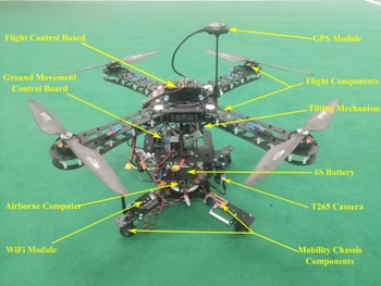
After the actuated components have been determined, the hardware architecture would be built, as shown in Fig. 8. Pixhawk V4 was selected as the flight control board and Arduino Uno as the ground locomotion control board to enhance the robot control performance, respectively. The airborne computer of the AQT-HR is an Nvidia Jetson TX2. The robot outdoor localization system relies on the GPS module to obtain horizontal localization in an open environment and a barometer to get altitude information; the localization accuracy of the GPS device is about 0.2 m. The indoor localization system relies on the T265 binocular camera and deploys the Visual-Inertial Odometry(VIO) algorithm to fuse IMU information with image processing information to obtain the robot’s pose. The realization of VIO is based on an open-source project called “vision
 $\_$
to
 $\_$
mavros” and processed in the Nvidia Jetson TX2. This processor is with 256 CUDA cores and 4 GB LPDDR4 memory, which makes the image processing in real-time can be satisfied.
The AQT-HR takes a hierarchical structure so that the main frame comprises panels, using 2 mm carbon fiber to ensure light weight and increased structural stiffness. All the fasteners and transmission parts, including the rods, mounts, and wheels, are manufactured using 3D printing chosen from PLA and with a tire size of 45 mm. For the tilting structure, the ABS material was selected to ensure the structure’s stiffness and strength. The prototype of the AQT-HR is shown in Fig. 9.
3. Dynamical analysis and motion control
3.1. Dynamics model of the flight mode
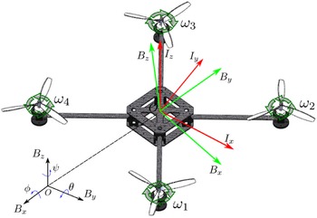
The actuator of the hybrid robot is the quadrotor configuration. Therefore, to improve the stability of locomotion, a dynamics model of the quadrotor will be established for the control method design [Reference Ahmed, Kumar and Patil31–Reference Nemati and Kumar33]. Firstly, we will establish two coordinate frames, the inertial frame
 $I_{x}I_{y}I_{z}$
, also known as the Earth Centered Earth Fixed coordinate, which is used to express the motion of the quadrotor relative to the ground, where the positive direction of the Z-axis is defined as the opposite of gravity and belongs to ENU coordinate frame. Next, the body-fixed frame
 $B_{x}B_{y}B_{z}$
will be established, which indicates the angular velocity and attitude information of the body itself, with its origin taken at the geometric center of the quadrotor. The definition of two frames is shown in Fig. 10.
The definition of the two coordinate frames.
 $ I_{x}I_{y}I_{z}$
is the inertial frame,
 $B_{x}B_{y}B_{z}$
is the body-fixed frame,
 $\omega _i$
is the rotation speed of the motor
 $i$
, and
 $\phi, \theta, \psi$
is roll, pitch, yaw angle of the quadrotor.

According to the above coordinate frames, we define the position and velocity of the quadrotor as
 $\boldsymbol{x} = (x, y, z)^{T}$
,
 $\boldsymbol{v} = (\dot{x}, \dot{y}, \dot{z})^{T}$
on the inertial frame. The attitude of the quadrotor can be defined on the body-fixed frame. Roll, pitch, and yaw angle of the robot can be represented as
 $\boldsymbol{\theta } = (\phi, \theta, \psi )$
and
 $\boldsymbol{\dot{\theta }} = (\dot{\phi }, \dot{\theta }, \dot{\psi })$
. Based on the theory of the coordinate transformation, the transformation matrix for angular velocities from the body-fixed frame (
 $\boldsymbol{\dot{\theta }}$
) to the inertial frame (
 $\boldsymbol{\omega }$
) is shown as:
 \begin{equation} \boldsymbol{\omega }=\left [\begin{array}{c@{\quad}c@{\quad}c} 1 & 0 & -\sin{\theta } \\[5pt] 0 & \cos{\phi } & \cos{\theta } \sin{\phi } \\[5pt] 0 & -\sin{\phi } & \cos{\theta } \cos{\phi } \end{array}\right ] \dot{\boldsymbol{\theta }} \end{equation}
The rotation matrix from the body-fixed frame to the inertial frame is
 \begin{equation} \boldsymbol{R}=\left [\begin{array}{c@{\quad}c@{\quad}c} C_{\psi } C_{\theta } & C_{\psi } S_{\theta } S_{\phi }-S_{\psi } C_{\phi } & C_{\psi } S_{\theta } C_{\phi }+S_{\psi } S_{\phi } \\[5pt] S_{\psi } C_{\theta } & S_{\psi } S_{\theta } S_{\phi }+C_{\psi } C_{\phi } & S_{\psi } S_{\theta } C_{\phi }-C_{\psi } S_{\phi } \\[5pt] -S_{\theta } & C_{\theta } S_{\phi } & C_{\theta } C_{\phi } \end{array}\right ] \end{equation}
where
 $S_{x} = \sin{x}$
,
 $C_{x} = \cos{x}$
. The rotation matrix
 $\boldsymbol{R}$
is orthogonal; thus,
 $\boldsymbol{R}^{-1} = \boldsymbol{R}^{T}$
. According to ref. [Reference Lee, Leok and McClamroch34], the torque vector of the quadrotor
 $\boldsymbol{\tau }_{B}$
can be derivated as:
 \begin{equation} \boldsymbol{\tau }_{B}=\left [\begin{array}{c} L k\left (\frac{\sqrt{2}}{2}\omega _{1}^{2}-\frac{\sqrt{2}}{2}\omega _{2}^{2}-\frac{\sqrt{2}}{2}\omega _{3}^{2}+\frac{\sqrt{2}}{2}\omega _{4}^{2}\right ) \\[5pt] L k\left (\frac{\sqrt{2}}{2}\omega _{1}^{2}+\frac{\sqrt{2}}{2}\omega _{2}^{2}-\frac{\sqrt{2}}{2}\omega _{3}^{2}-\frac{\sqrt{2}}{2}\omega _{4}^{2}\right ) \\[5pt] b\left (\omega _{1}^{2}-\omega _{2}^{2}+\omega _{3}^{2}-\omega _{4}^{2}\right ) \end{array}\right ] \end{equation}
where
 $L$
represents the distance between the motor and the quadrotor’s center,
 $k$
is the thrust coefficient, and
 $b$
is the torque coefficient.
Based on Newton’s Second Law, the mechanical analysis of the quadrotor can be represented as:
 \begin{equation} \begin{aligned} m \ddot{\boldsymbol{x}} &=\left [\begin{array}{c} 0 \\[5pt] 0 \\[5pt] m \boldsymbol{g} \end{array}\right ]+\boldsymbol{R} \boldsymbol{T}_{\boldsymbol{B}}+ \boldsymbol{F}_{D} \\[5pt] \boldsymbol{T}_{\boldsymbol{B}} &=\sum _{i=1}^{4} T_{i}=k\left [\begin{array}{c} 0 \\[5pt] 0 \\[5pt] \sum \omega _{i}^{2} \end{array}\right ] \end{aligned} \end{equation}
where
 $\ddot{\boldsymbol{x}}$
represents the accelerated velocity,
 $\boldsymbol{T}_{B}$
represents the thrust of the quadrotor on the body-fixed frame, and
 $\boldsymbol{F}_{D}$
represents the drag force which can be ignored at a low speed.
In addition, the dynamics model of the quadrotor contains the torque analysis according to Euler’s Theorem:
 \begin{equation} \boldsymbol{I} \dot{\boldsymbol{\omega }}+\boldsymbol{\omega } \times (\boldsymbol{I} \boldsymbol{\omega })=\boldsymbol{\tau }_B \end{equation}
For an intuitive representation, the torque analysis can be derivated as:
 \begin{equation} \dot{\boldsymbol{\omega }}=\left [\begin{array}{l} \tau _{\phi } I_{x x}^{-1} \\[5pt] \tau _{\theta } I_{y y}^{-1} \\[5pt] \tau _{\psi } I_{z z}^{-1} \end{array}\right ]+\left [\begin{array}{c} \frac{I_{y y}-I_{z z}}{I_{x x}} \omega _{y} \omega _{z} \\[5pt] \frac{I_{z z}-I_{x x}}{I_{y y}} \omega _{x} \omega _{z} \\[5pt] \frac{I_{x x}-I_{y y}}{I_{z z}} \omega _{x} \omega _{y} \end{array}\right ] \end{equation}
where
 $\boldsymbol{\omega }$
is the vector of angular velocity, and
 $I_{xx}, I_{yy}, I_{zz}$
are the rotational inertia of the body on the
 $x, y$
, and
 $z$
axes, respectively.
Combining Eqs. (2), (5), and (7), the analysis model of the quadrotor can be transformed to a form of state space:
 \begin{equation} \begin{aligned} &\dot{\boldsymbol{x}}_{1}=\boldsymbol{x}_{2} \\[5pt] &\dot{\boldsymbol{x}}_{2}=\left [\begin{array}{c} 0 \\[5pt] 0 \\[5pt] -g \end{array}\right ]+\frac{1}{m} \boldsymbol{R} \boldsymbol{T}_{\boldsymbol{B}} \\[5pt] &\dot{\boldsymbol{x}}_{3}=\left [\begin{array}{c@{\quad}c@{\quad}c} 1 & 0 & -\sin{\theta } \\[5pt] 0 & \cos{\phi } & \cos{\theta } \sin{\phi } \\[5pt] 0 & -\sin{\phi } & \cos{\theta } \cos{\phi } \end{array}\right ]^{-1} \boldsymbol{x}_{4} \\[5pt] &\dot{\boldsymbol{x}}_{4}=\left [\begin{array}{c} \tau _{\phi } I_{x x}^{-1} \\[5pt] \tau _{\theta } I_{y y}^{-1} \\[5pt] \tau _{\psi } I_{z z}^{-1} \end{array}\right ]+\left [\begin{array}{c} \frac{I_{y y}-I_{z z}}{I_{x x}} \omega _{y} \omega _{z} \\[5pt] \frac{I_{z z}-I_{x x}}{I_{y y}} \omega _{x} \omega _{z} \\[5pt] \frac{I_{x x}-I_{y y}}{I_{z z}} \omega _{x} \omega _{y} \end{array}\right ] \end{aligned} \end{equation}
where
 $\boldsymbol{x}_{1}$
represents the position of the quadrotor,
 $\boldsymbol{x}_{2}$
represents the velocity,
 $\boldsymbol{x}_{3}$
represents the attitude angle of the quadrotor,
 $\boldsymbol{x}_{4}$
represents the angular velocity, and the drag force
 $\boldsymbol{F}_{D}$
is ignored.
3.2. Dynamics model of the ground movement mode
The ground movement mode contains the turning and forward motion of the hybrid robot. The output variables of the designed controller are horizontal positions
 $x, y$
, while there are three input variables which are the tilting angle
 $\gamma$
, the quadrotor’s thrust
 $F_{T}$
, and the steering angle
 $\alpha$
. Two outputs correspond to three inputs, belonging to a redundantly driven control model. To reduce the difficulty of control, an assumption is considered as follows:
Assumption 1. The four motors take the same rotation speed, and the thrust generated by each propeller is the same, with the value remaining constant throughout the ground movement mode.
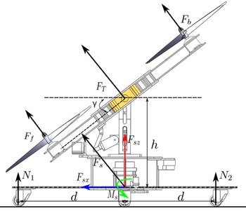
According to Theoretical Mechanics, a total thrust will be generated at the center of the quadrotor, as shown in Fig. 11. Therefore, based on Fig. 11 and considering the robot’s forward motion on the ground, the force analysis of the hybrid robot can be derivated as:
 \begin{equation} \begin{aligned} &F_{sx}=F_{T} \sin{\gamma } \\[5pt] &F_{sz} = F_{T} \cos{\gamma } \\[5pt] &F_{sx}-\mu (N_{1}+N_{2})-F_{D} = 0\\[5pt] &mg - (N_{1}+N_{2}+F_{sz})=0 \\[5pt] \end{aligned} \end{equation}
where
 $\mu$
is the coefficient of rolling friction, and
 $F_{D}$
is the air resistance.
Dynamics model of the forward motion.
 $F_{f}$
is the thrust generated by the two former motors,
 $F_{b}$
is the thrust generated by the two rear motors,
 $F_{T}$
is the total thrust,
 $M_{s}$
is the capsizing moment,
 $h$
represents the distance between the center of the quadrotor and the geometric center of the chassis, and
 $d$
represents the distance from the wheels to the geometric center of the chassis.

The titling angle
 $\gamma$
is selected as the control variable in the ground movement mode. It causes a gyroscopic moment
 $M_{\text{gyro}}$
which is generated by the relative motion of the quadrotor’s tilting and the motor’s rotation. While the tilting motion occurs only on the Y-axis of the quadrotor, which means the gyroscopic moment can be determined as:
 \begin{equation} M_{\text{gyro}} = J_{xy} \vec{\omega }_{y} \times (\vec{\omega }_{1} - \vec{\omega }_{2} +\vec{\omega }_{3} - \vec{\omega }_{4}) \end{equation}
where
 $J_{xy}$
is the rotational inertia,
 $\vec{\omega }_{y}$
is the vector of tilting angular velocity,
 $\vec{\omega }_{i}$
is the rotational vector of each motor, and the direction of
 $M_{\text{gyro}}$
is around the X-axis, satisfying the right-hand rule. According to the Assumption 1, the rotational speed of each motor remains the same so that the gyroscopic moment will be zero.
The capsizing moment
 $M_{s}$
caused by the thrust’s horizontal component is hazardous, while it can be offset by the torque from the ground support force, as shown below:
 \begin{equation} M_{s} +N_{2}d - N_{1}d = 0, M_{s} = F_{T} h \sin\gamma \end{equation}
where, when the rear support force
 $N_{2}$
turns to zero, the robot is in the critical condition of flipping over, which must be avoided. Therefore, combined with the balance condition Eq. (9), the thrust and the support force can be calculated as:
 \begin{equation} \begin{aligned} 2 N_{1}d +F_{T}(d \cos\gamma - h \sin\gamma ) - mgd &= 0 \\[5pt] F_{T} (h \sin\gamma +d \cos\gamma ) -mgd &= 0 \end{aligned} \end{equation}
to achieve the normal ground movement, and the following requirements should be satisfied:
 \begin{equation} \begin{aligned} F_{T} \sin\gamma -\mu (N_{1} + N_{2}) &\geq 0 \\[5pt] mg - F_{T} \cos\gamma -N_{1}-N_{2} &= 0 \end{aligned} \end{equation}
Considering the friction of the ground, the critical condition of the robot’s ground movement can be represented as:
 \begin{equation} \begin{aligned} \frac{umg}{\mu \cos\gamma +\sin\gamma } \leq F_{T} & \leq \frac{mgd}{h \sin\gamma +d \cos \gamma } \\[5pt] 0 \leq N_{1} & \leq \frac{mgd - F_{T}(d\cos\gamma - h\sin\gamma )}{2d} \end{aligned} \end{equation}
After that, the dynamics model of the robot’s forward motion can be derivated:
 \begin{equation} \begin{aligned} m \ddot{x} &= F_{sx} - \mu (N_{1}+N_{2}) -F_{D} \\[5pt] &= F_{T} \sin{\gamma } - \mu (mg - F_{T} \cos{\gamma }) -F_{D} \end{aligned} \end{equation}
and the state space representation can be represented as:
 \begin{equation} \begin{aligned} &\dot{x}_{1} = x_{2} \\[5pt] &\dot{x}_{2} = \frac{F_{T}}{m}(\sin{\gamma } + \mu \cos{\gamma }) - \mu g - \frac{F_{D}}{m} \end{aligned} \end{equation}
where
 $x_{1}$
represents the position of the robot, and
 $x_{2}$
represents the velocity of the robot.
The steering model of the hybrid robot.

The driving force of the ground steering structure comes from the thrust’s horizontal component, the point of force application is in the center of the chassis, and the steering model is a front steering mid-drive configuration, as shown in Fig. 12. Based on a symmetrical chassis configuration and the information in Fig. 12, the steering radius can be calculated as follows:
 \begin{equation} R_{c} = \frac{L_c}{2 \sin{\frac{\alpha }{2}}} \end{equation}
Following the development of the flight dynamics model and the ground mode dynamics model, the control method for the dual-modal motion of the robot will be proposed in the next part.
3.3. The design of the control method
The control method aims to improve the control accuracy and stability of the robot’s aerial locomotion and reduce the risk of falling. This paper proposes a model-feedforward PID control method for implementing the robot’s aerial locomotion, and PD control is adopted to achieve the robot’s ground locomotion.
The model-feedforward PID approach is intended to accommodate the motion characteristics of the hybrid robot. From structural consideration, the AQT-HR system can be considered as a quadrotor with a hanging under-chassis. Compared to the control problem of a normal quadrotor, the downward of the robot’s center of gravity and the increase in gravitational torque make control more difficult and its parameters harder to adjust. Therefore, the traditional PID algorithm is improved by introducing the dynamics model into it, reducing parameter adjustment complexity while increasing flight control’s efficiency. To facilitate the design of the controller, the robot’s flight dynamics model is linearized, assuming that pitch and yaw alter tiny and the total thrust is approximate to the robot’s weight during the flight, with the following mathematical form:
 \begin{equation} \sin{\phi } \approx \phi, \cos{\phi } \approx 1, \sin{\theta } \approx \theta, \cos{\theta } \approx 1, T_{B} \approx mg \end{equation}
According to the mathematical form and the dynamics model (8), a horizontal position control method for the robot can be obtained as follows:
 \begin{equation} \left [\begin{array}{c} \ddot{p}_{x}\\[5pt] \ddot{p}_{y} \end{array}\right ] = g \left [\begin{array}{c@{\quad}c} \cos{\psi } & -\sin{\psi } \\[5pt] \sin{\psi } & \cos{\psi } \end{array}\right ] \left [\begin{array}{c@{\quad}c} 0 & 1\\[5pt] -1 & 0 \end{array}\right ] \left [\begin{array}{c} \phi \\[5pt] \theta \end{array}\right ] \end{equation}
where
 $\ddot{p}_{x}$
is the second derivative of the position on the robot’s x-direction,
 $\ddot{p}_{y}$
is the second derivate of the position on the robot’s y-direction,
 $\phi$
determines the roll angle, and
 $\theta$
determines the pitch angle. The inputs of the controller are the angle of attitude, and there will be a transformation:
 \begin{equation} \left [\begin{array}{c} \phi \\[5pt] \theta \end{array}\right ] = \frac{1}{g} \left [\begin{array}{c@{\quad}c} \sin{\psi } & -\cos{\psi } \\[5pt] \cos{\psi } & \sin{\psi } \end{array}\right ] \left [\begin{array}{c} \ddot{p}_{x} \\[5pt] \ddot{p}_{y} \end{array}\right ] \end{equation}
The desired transition process for the robot’s horizontal position control is:
 \begin{equation} \begin{aligned} &e_{p_{x}} = p_{xd}-p_{x} \\[5pt] &e_{p_{y}} = p_{yd} - p_{y} \\[5pt] &\ddot{e}_{p_{x}} =\ddot{e}_{p_{xd}}-\ddot{e}_{p_{x}} = k_{p} e_{p_{x}}+k_{i} \sum _{i=0}e_{p_{x}} dt +k_d \frac{d{e}_{p_{x}}}{dt} \\[5pt] &\ddot{e}_{p_{y}} =\ddot{e}_{p_{yd}}-\ddot{e}_{p_{y}} = k_{p} e_{p_{y}}+k_{i}\sum _{i=0} e_{p_{y}} dt +k_d \frac{d{e}_{p_{y}}}{dt} \end{aligned} \end{equation}
where
 $e_{p_{x}}$
determines the error between the desired position
 $p_{xd}$
and the actual position
 $p_{x}$
, and the same applies to
 $e_{p_{y}}$
. For position control, the desired acceleration of the robot is 0, so combining Eqs. (20) and (21), the mathematical form of the horizontal position controller for the hybrid robot can be derivated as:
 \begin{equation} \begin{aligned} &\phi = \frac{1}{g}(\sin{\psi }(k_{p} e_{p_{x}}+k_{i} \sum _{i=0}e_{p_{x}} dt +k_d \frac{d{e}_{p_{x}}}{dt}) -\cos{\psi }(k_{p} e_{p_{y}}+k_{i} \sum _{i=0}e_{p_{y}} dt +k_d \frac{d{e}_{p_{y}}}{dt}))\\[5pt] & \theta = \frac{1}{g}(\cos{\psi }(k_{p} e_{p_{x}}+k_{i} \sum _{i=0}e_{p_{x}} dt +k_d \frac{d{e}_{p_{x}}}{dt}) +\sin{\psi }(k_{p} e_{p_{y}}+k_{i} \sum _{i=0}e_{p_{y}} dt +k_d \frac{d{e}_{p_{y}}}{dt})) \end{aligned} \end{equation}
where
 $k_{p}, k_{i}, k_{d}$
are the parameters of the PID controller and should be adjusted to achieve a proper output. The actual control process requires the conversion of the Euler angles into quadratic values, which are solved by the processor to achieve the horizontal position control.
Next, the robot’s height control will be designed. As the same as the design principle of the horizontal position controller, the simplified linear model of the height controller is:
 \begin{equation} \ddot{p}_{z} = g - \frac{f}{m} \end{equation}
The thrust force
 $f$
is the control input corresponding to the robot’s acceleration. In addition, a P-controller for the outer loop velocity is added to avoid the motion oscillation, which results in a height controller of the robot:
 \begin{equation} \begin{aligned} &v_{zd} = k_{pv} (p_{zd} - p_{z}) \\[5pt] &e_{zv} = v_{zd} - v_{z} \\[5pt] &f = mg + m(k_{pf}e_{vz} + k_{if}\sum _{i=0} e_{vz} dt +k_{df} \frac{de_{vz}}{dt}) \end{aligned} \end{equation}
where
 $k_{pv}$
is the coefficient of the P-controller, and
 $v_{zd}$
is the desired velocity on the z-axis, which is generated by the P-controller. After that, the design of the model-feedforward PID controller is completed, whose parameters are shown in Table I. The motion controller for the hybrid robot’s flight mode is shown in Fig. 13.
The parameters of the model-feedforward PID control method.

The motion controller for the hybrid robot’s flight mode,
 $\boldsymbol{p}_{d}=(p_{xd}, p_{yd}, p_{zd})$
,
 $\boldsymbol{p}=(p_{x}, p_{y}, p_{z})$
,
 $\boldsymbol{v}=(v_{x}, v_{y}, v_{z})$
and
 $\boldsymbol{q} = (\phi, \theta, \psi )$
.

4. Results and analysis
In this section, the dual-modal mobility will be verified by experiments, followed by experiments on the robot’s autonomous movement control, showing that the robot can switch modes autonomously to achieve obstacle traversing. Additionally, all the indoor experiments are conducted in a closed space with a length of 24 m and a width of 10 m, and no man will pass by. The manipulator was in another room and watched the robot through a window, so the person’s safety was guaranteed. Besides, the green floor is placed with soft materials to avoid damage to the robot.
4.1. The verification of the dual-modal mobility
4.1.1. The motion performance of the AQT-HR
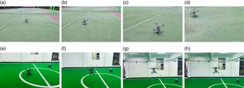
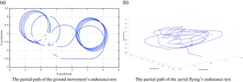
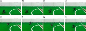
The process of the robot’s ground movement is shown in Fig. 14. In addition, the robot’s ground locomotion endurance was tested in an indoor environment, using a circle test scheme with a battery whose full charge voltage is 25.0 V and depletion voltage is 22.5 V. The partial motion path of the test is shown in Fig. 15a. When the battery’s voltage descended to 22.5 V, the duration in ground movement mode was recorded as 36 min 54 s. Same as the former, the process of the robot’s aerial flying is shown in Fig. 14.
The verification of the ground movement and aerial flying ability. (a)–(d) represent the robot’s ground movement, (e)–(h) represent the robot’s flight mode.

The experiment of the robot’s endurance test.

Similarly, the endurance test was carried out in the flight mode, and the motion path of the test is shown in Fig. 15b. After testing, the robot’s flight duration was recorded as 6 min 42 s. In a word, the robot has a long duration of ground movement and less duration of flight mode, it can be explained because the flying motion needs to overcome the weight of the whole robot, and the energy consumption is higher. So the default locomotion mode of the robot is set as ground movement mode, and the flight mode is used to traverse obstacles or irregular terrain.
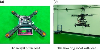
Besides, the robot can deliver loads, as shown in Fig. 16. This load weighed 1089 g and was attached to the bottom of the robot. After loading the extra weight, the AQT-HR can still take off and hover, which means there is room to assemble other sensors or computational units to improve the robot’s motion performance.
The flying experiment of the robot with load.

4.1.2. The maneuverability of dual-modal mobility
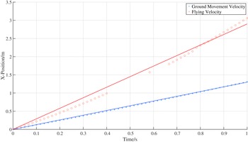
The motion performance of the robot includes the maximum velocity of the dual-modal mobility, which can be measured by deploying a motion capture system called OptiTrack. The sampling frequency was set as 60 Hz, and the sampling time was 1 s. The robot’s locomotion in the x-direction was tracked, and a scatter plot of its trajectory was plotted, as shown in Fig. 17. Due to the high speed of flying, some trajectory points are lost, so there is a gap in the flying scatter plot. Nevertheless, the measuring results show that the hybrid robot can move quickly in the air and on the ground with a velocity of 2.9 m/s for flying and 1.3 m/s for ground movement. Although it could go faster, we curtailed the speed for ensuring indoor environment safety.
The dual-modal locomotion velocity of the hybrid robot. The blue line is the position curve fitted to the ground movement scatter points, and the red line is the position curve fitted to the flying scatter points.

4.2. The experiments of autonomous movement
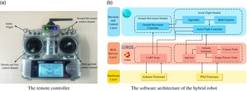
The AQT-HR can be used in two operation modes: remote control and autonomous movement. When the robot is operated in remote control mode, it receives control signals from a remote controller, shown in Fig. 18a. The remote controller can operate the robot to achieve both ground movement and flying locomotion, and it also includes a safety trigger that can switch the robot operation mode between the remote control and autonomous movement. The robot’s autonomous movement relies on the software architecture, which consists of three main parts: the decision and control layer to make a mode-switching decision, the ROS service layer to build communication between ROS and hardware, and the hardware layer to activate the dual-modal drivers. The software architecture of the hybrid robot is shown in Fig. 18b.
The remote controller and the software architecture of the hybrid robot.

4.2.1. Taking off and hovering
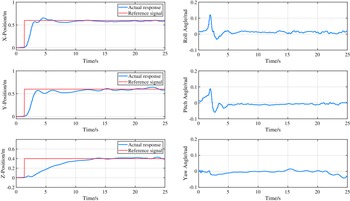
Firstly, the autonomous take-off and landing experiment was conducted to verify that the hybrid robot possesses the basic autonomous flight ability, as shown in Fig. 19. Then, the position and attitude curves can be obtained by recording the data of the experiment through rosbag, as shown in Fig. 20.
The hybrid robot’s autonomous take-off and landing experiment. The target point is (0.6 m, 0.6 m, 0.4 m), whose coordinate frame takes the robot’s beginning position as the origin and the robot’s head toward the front, following the right-hand rule.

The response curve for the autonomous take-off of the hybrid robot. The red line represents the reference signal, and the blue line represents the actual response.

From Fig. 20, with the model-feedforward PID control law, there is a rise time of around 3 s and a setting time of around 10 s in the x-direction position control of the robot; a rise time and a setting time of around 3 s and 11 s in the y-direction, respectively. In addition, the robot gets a rise time of around 13 s and reaches a steady state directly in the z-direction. When the robot reaches the target position, the alteration is less than 5% in all directions, and all attitude angles are changed to less than 2
 $^{\circ }$
, which means that the robot reached a stable hover. For attitude control, the maximum values of roll and pitch angles are around 0.12 rad (7
 $^{\circ }$
), consistent with the small angle assumptions and linear simplifications made previously. Since the yaw motion is not involved, the controller of the yaw angle is not performed.
4.2.2. Traversing the obstacles
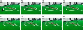
The hybrid robot’s autonomous mode switching depends on a single-line LIDAR installed in the forward position. When an obstacle is detected at a distance of less than 0.5 m, the robot will switch from ground movement mode to aerial flight mode. After traversing the obstacle by flying, the robot alters the tilting angle to 0
 $^{\circ }$
and returns to the ground movement mode. The demonstration is shown in Fig. 21.
The experiment of autonomous traversing obstacle. The whole experiment is divided into five stages. Stage 1: the hybrid robot departed at the initial position (0, 0, 0), adopting the ground movement mode, and after moving 1.5 m, the sensor detected the obstacle; stage 2: switching to flight mode and taking off, hovering at (1.5, 0, 0.5) stably; stage 3: flying over the obstacle and hovering at (3, 0, 0.5); stage 4: executing landing process which makes the z-position back to 0; stage 5: landing completed, switching to ground movement mode and then running forward. The final position of the robot is (6.5, 0, 0).

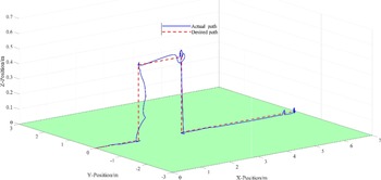
The entire locomotion path is shown in Fig. 22. As can be seen, the obstacles in this experiment are long and narrow, which are set to simulate steps and fences in a real-world scenario, which an ordinary wheeled ground-mobile robot cannot traverse quickly. Our hybrid robot can traverse the obstacles easily by deploying the aerial flight mode, demonstrating that the AQT-HR possesses the ability to switch modes autonomously and can traverse the complex terrains easily.
The locomotion path for autonomously traversing the obstacle. The green plane shown is the field, the red dashed line is the reference trajectory, and the solid blue line is the actual value obtained from the visual odometer.

4.3. Energy consumption for movement mode
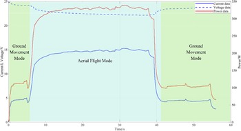
In the experiment on autonomous obstacle traversing, the data related to the voltage and current of the robot are drawn in Fig. 23. It can be seen that the current
 $I_g$
and power
 $P_g$
values are maintained at around 5 A and 110 W in the ground movement mode, while the current
 $I_a$
and power
 $P_a$
maintained at 15 A and 340 W in the flight mode. In addition, we measure the standby power
 $P_s$
of the vehicle, including onboard computer, controllers, and other components, which is 21 W. So we have the power saving efficiency:
 \begin{equation} \eta = (1-\frac{P_g-P_s}{P_a - P_s})\times 100\% \approx 72\% \end{equation}
The result suggests that the AQT-HR is more energy efficient than an ordinary UAV. In addition, the ground movement mode’s potential was not fully exploited, as the quadrotor tilting angle was limited to 20
 $^{\circ }$
to ensure indoor experiment safety, reducing the driving force. There will be a significant reduction in energy consumption for the same speed of movement if the tilting angle alters to a maximum value which is 37.5
 $^{\circ }$
.
Energy consumption of the hybrid robot in the experiment of traversing obstacle autonomously. The current and voltage values are shown on the left-hand axis, and the power curve is shown on the right-hand axis.

5. Conclusion
This paper proposes a prototype of the AQT-HR system. The hybrid robot consists of a quadrotor to generate the driving force, a passive under-chassis to realize the ground movement, and a tilting mechanism to alter the direction of the driving force. Furthermore, a model-feedforward PID control method based on the analysis of the dynamics was adopted to improve flying stability. After that, some experiments were conducted to demonstrate the ideal control performance of the control law in an indoor environment. At last, we showed that the robot is capable of autonomous mode-switching locomotion and verified that the robot has lower energy consumption in ground movement and higher maneuverability in aerial flight, which conform to the original design goal. The proposed robot AQT-HR has the potential to be applied to the real world and can contribute to the exploring and searching tasks.
This paper presents exploratory research on the design and control of terrestrial/aerial hybrid locomotion robots based on the system design concept. At present, there are still much more aspects for improvement of the AQT-HR, and future work can be conducted in the following: (a) optimizing the power module of the robot to ensure the reliability of the system; (b) optimizing the redundancy control of the ground movement mode, adding the dual-control of inclination and thrust, and designing reliable ground motion control algorithms under the condition of redundant inputs; (c) the robot’s mode-switching controller can be optimized to achieve fast ground-to-air and smooth air-to-ground mode changing with advanced switching control theory. In a word, we will build a mature and reliable autonomous robot system and realize the practical application in the future.
Author contributions
Daoxun Zhang and Ming Xu conceived and designed the study. Huimin Lu and Zhiqiang Zheng suggested the framework of this article. Pengming Zhu, Ce Guo, and Zhengyu Zhong help conduct experiments. Daoxun Zhang wrote the article.
Financial support
This work was supported by the National Natural Science Foundation of China [U1813205, U1913202].
Competing interests
The authors declare no competing interests exist.
Ethical approval
Not applicable.
Supplementary material
The supplementary material for this article can be found at https://doi.org/10.1017/S0263574723001376.