
I. INTRODUCTION
Due to the worldwide ever-increasing demand for clean and renewable energies, a great deal of efforts have been devoted to exploring various energy devices. The renewable energies, such as solar energy and wind energy, have shown their potentials for the future society. However, the inherent disadvantages of intermittence and uneven regional distribution have strongly restricted their large-scale applications. In this regard, it is extremely urgent to produce and employ highly efficient, stable, and environmentally friendly renewable energies. As one of the most important energy devices, electrocatalytic water splitting, which can produce hydrogen and oxygen simultaneously, has attracted extensive attention owing to its highly efficient and commercial CO2-free process.Reference Chen, Duan, Jaroniec and Qiao1–Reference Feng, Xu, Dong, Lu, Tong and Li6 Unfortunately, one of the major hurdles of water splitting is the anodic oxygen evolution reaction (OER), which involves the complex process of four-electron transportation and one oxygen molecule formation.Reference Wang, Xiao, An, Long, Zheng, Lu, Tong and Yang7–Reference Lu, Gu, Wang, Wu, Liao and Li12 Up to now, the precious oxides RuO2 and IrO2 have been widely reported as highly efficient OER electrocatalysts.Reference Wohlfahrt-Mehrens and Heitbaum13–Reference Browne, Nolan, Twamley, Duesberg, Colavita and Lyons15 However, these noble metal oxides suffer from drawbacks of high cost and poor chemical stability in the alkaline solution. IrO2 and RuO2 were unstable since they can transfer into higher valent oxides. Consequently, it is important to design and synthesize cheap, durable, and highly effective OER catalysts.
Transition-metal phosphide (TMP) has emerged as one of the most important non-noble-metal electrocatalysts. Recently, metal phosphides, such as FeP, Ni2P, NiP, Co2P, and CoP, have shown their potential for the fabrication of low-cost and highly active water splitting catalysts.Reference Han, Chen, Sun, Xu and Du16–Reference Yu, Zhao, Feng, Hu, Zhang, Zeng, Tong and Lu21 For example, Du et al.Reference Han, Chen, Sun, Xu and Du16 first reported the synthesis of noble-metal-free nickel phosphide (Ni2P) nanowires and explored its catalytic performance for water oxidation. The Ni2P nanowire electrode achieved the lowest onset potential of around 1.54 V [versus reversible hydrogen electrode (RHE)] and a Tafel slope of 60 mV/dec in 1.0 mol/L KOH solution. Wang et al.Reference Wang, Lin, Xu, Tong and Li22 reported a new type of Ni2P–CoP hybrid nanosheet arrays on flexible carbon cloth (Ni2P–CoP HNSAs/CC) for the hydrogen evolution reaction. Due to the special surface effects of hybrid nanosheet arrays and synergistic effects between Ni2P and CoP, the Ni2P–CoP HNSAs/CC showed excellent electrocatalytic performance for the hydrogen evolution reaction in both acid and alkaline solutions.
Compared to these TMPs, the present CoP nanomaterials displayed efficient and durable electrocatalytic activity toward the hydrogen evolution reaction at cathodic potentials in alkaline solutions. However, the OER performance of these CoP nanomaterials was dissatisfactory since they suffered dramatic metamorphosis, morphology transformation, and unique change of microscopic local environments under high anodic potential or oxygen-evolution conditions. The CoP nanomaterial electrodes lost its activity toward water oxidation during the test or suffered from poor chemical stability in the alkaline solution. Different kinds of methods have been devoted to solve these problems. One of the effective methods is to combine the CoP nanoparticle with carbon materials, such as carbon nanotube (CNT) and graphene, to reduce the dramatic metamorphosis and morphology transformation. The carbon materials can be also used to enhance the conductivity of the composited electrodes, as well as the water splitting activity. For example, Hou et al.Reference Hou, Cao, Fu and Chen23 reported the preparation of CoP nanoparticles with multi-walled carbon nanotube (MWCNT). It showed a remarkable activity for water splitting, which showed an onset overpotential of 290 mV, a Tafel slope of 50 mV/dec, and an overpotential of 330 mV to achieve the current density of 10 mA/cm2 in 1.0 mol/L NaOH. Huang et al.Reference Huang, Yu, Yang, Zhao, Han, Liu and Qiu24 developed a strategy to prepare cobalt phosphide/graphene (CoP/Gr) composited architectures. Due to the synergetic effects between the CoP with lots of electroactive sites and Gr with enhanced charge transfer, the CoP/Gr composited architectures only demanded a low overpotential of around 292 mV to achieve current density of 10 mA/cm2 for the OER in 1 mol/L KOH. On the other hand, as a noticeable method, the doping method with metal or nonmetal elements has been proved to be an effective way to greatly modify the physicochemical and electronic properties and the activity for the hydrogen evolution, which was confirmed by many studies in the past few years.Reference Chen, Duan, Jaroniec and Qiao1,Reference Zeng, Han, Zhao, Zeng, Yu, Liu, Tang, Tong and Lu25–Reference Wang, Gong, Chou, Pan, Chen, Wu, Lin, Guan, Yang, Chen, Wang, Hwang, Chen and Dai27 Some studies demonstrated that the HER activity of CoP can be further improved by doping hetero-atom cerium (Ce-doped CoP), and the electrocatalytic activities are highly related to the Ce doping ratio.Reference Gao, Yan, Cheung, Xia, Zhou, Qin, Wong, Qu, Chang and Ho28 Compared to the pristine CoP, Ce doping can reduce the charge transfer resistance but increase the electrochemically active surface area of the catalysts. In addition, the results of DFT (Density Functional Theory) calculation indicated that hydrogen adsorption energy decreased with Ce doping and modified the Bader charge of Co for Ce-doped CoP, which can facilitate the hydrogen evolution reaction with lower overpotential and Tafel slopes. Despite these significant achievements, the development of alternative cobalt-based electrocatalysts with effective activity and excellent stability for the OER is still urgent but remains challenging.
Here, we reported the design and synthesis of Mn-doped CoP nanosheet arrays on flexible carbon cloth (denoted as Mn–CoP/CC) as a robust oxygen revolution catalyst. Additionally, the flexible carbon cloth possessed novel 3D nanostructures, which were beneficial for promoting the electrochemical performances of the electrodes. To enhance the activity of these catalysts, the carbon cloths were first treated in a mixed solution containing concentrated H2SO4 and concentrated HNO3 (V/V = 1:1) for 40 min to produce porous surface with abundant oxygen groups. Then, Mn doped CoP was coated on the treated carbon cloths by a simple hydrothermal method. By analyzing the doping amount of the Mn element and the activity of water oxidation, it was found that CoP/CC with Mn doping amount of 5% [denoted as Mn(5%)–CoP/CC] had the highest water splitting current density and lowest Tafel slope. This novel Mn(5%)–CoP/CC electrode delivered the overpotential of 317 mV for water splitting with a current density of 10 mA/cm2, a Tafel slope of ∼65.1 mV/dec, and excellent stability over 16 h in 1.0 mol/L KOH, which is superior or comparable to the most of the reported cobalt-based catalysts. Moreover, the three-dimensional (3D) structures of the Mn–CoP/CC are beneficial for high electrocatalytic performance due to the intrinsic large specific surface area and high mass transfer between the catalyst and the solution. It is believed that these findings would help us to develop highly effective and stable electrocatalysts for the oxygen evolution.
II. EXPERIMENTAL SECTION
A. Preparation of Mn doped CoP/CC
All reagents in this study were used directly without any purification. Co(NO3)2 6H2O, NH4F, urea, MnCl2 4H2O, concentrated H2SO4, and concentrated HNO3 were purchased from Guangzhou Chemical Reagent Factory (Guangzhou, China). The carbon cloths (CC, WOS 1002 12.5 mg/cm2, the thickness is 360 μm) were purchased from PHYCHEMi Co. Ltd. (Hong Kong, China). First, the carbon cloth was oxidized in a mixed solution containing concentrated H2SO4 and concentrated HNO3 (V/V = 1:1) for 40 min to produce porous surface with abundant oxygen groups. Then, the CC was cleaned ultrasonically in ethanol, deionized water, and acetone for 10 min. Before the synthesized process, the cleaned CC was rinsed in ethanol and dried in air naturally.
In a typical synthesis of Mn doped Co(OH)F/CC precursors, 1 mmol Co(NO3)2 6H2O, 2 mmol NH4F, 5 mmol urea, and a specific amount of MnCl2 4H2O (2, 5, and 10 wt%) were dissolved in 30 mL deionized water under strong stirring for one hour at room temperature. Then, the solution was transferred into a Teflon autoclave with a piece of clean oxidized carbon cloth (2 × 3 cm2). The autoclave was immediately put into an electric oven and heated at 120 °C for 5 h. After that, the autoclaves cooled down to the room temperature naturally. The Mn doped Co(OH)F/CC samples were thoroughly washed with deionized water and ethanol and finally dried at 60 °C in an electric oven overnight. To obtain the Mn doped CoP/CC, the as-prepared Mn doped Co(OH)F/CC and NaH2PO2 powder were placed separately in a horizontal tube furnace and the NaH2PO2 powder was placed at the upstream side of the furnace. Subsequently, the furnace was heated to 350 °C and kept at this temperature for about 2 h from room temperature with a ramping rate of 2 °C/min in Ar atmosphere. The furnace was then cooled down to room temperature naturally. At last, the obtained black solid Mn doped CoP/CC samples were washed subsequently by water and ethanol three times and dried at 60 °C in an electric oven overnight.
In comparison, the RuO2/CC electrode was also prepared. Generally speaking, RuO2 ink solution (2 mg/mL) was obtained by mixing 20 mg RuO2 powder with a solution of 8 mL deionized water, 2 mL isopropanol, and 50 μL Nafion 117. Then, the above ink solution was dispersed by sonicating for one hour to form a homogeneous ink. At last, the RuO2/CC electrode was constructed by dropping 100 μL RuO2 homogeneous ink onto a clean CC to reach RuO2 mass loading of around 0.20 mg/cm2 and dried at 60 °C in an electric oven overnight.
B. Characterizations and electrochemical measurements
The field emission scanning electron microscopy (FE-SEM) images of the as-synthesized products were obtained on JSM-6701F (JEOL Ltd., Tokyo, Japan) with a 20 kV accelerating voltage. The X-ray diffraction (XRD) patterns were measured on a Ultima-IV (Rigaku Co., Tokyo, Japan) diffractometer using Cu Kα radiation (λ = 1.5418 Å) with a 40 kV accelerating voltage and a 20 mA current density. X-ray photoelectron spectroscopy (XPS) was characterized by ESCALab250 (Thermo Scientific, Waltham, Massachusetts). An Al Kα X-ray source with a power of 250 W was used. All the binding energy positions were referenced to the C 1s peak of the surface adventitious carbon (at 284.6 eV). The transmission electron microscopy (TEM) images were obtained on JEM2010-HR (JEOL Ltd., Tokyo, Japan) with a 200 kV accelerating voltage. For TEM and high-resolution transmission electron microscopy (HR-TEM) measurements, the samples were first dispersed into ethanol. Then, the solution was sonicated for at least 30 min to form uniform ink. At last, the ink was dropped on an ultrathin carbon film copper mesh and allowed to dry in an oven at 60 °C overnight prior to these measurements.
All the electrochemical measurements were carried out in a three-electrode cell on a CHI 760D electrochemical workstation (CH Instruments, Inc., Shanghai, China) at room temperature. The electrolyte solution was 1.0 mol/L KOH. The working electrode is the prepared CoP/CC and different Mn doped CoP/CC and RuO2/CC electrodes. A Pt mesh (100 mesh, 1 cm2) was used as the counter electrode and a saturated Ag/AgCl electrode was used as the reference electrode. The reference potential of the Ag/AgCl electrode was calibrated with respect to RHE in all measurements in 1.0 mol/L KOH by Eq. (1),
 $$E\left( {{\rm{RHE}}} \right) = E\left( {{{{\rm{Ag}}} / {{\rm{AgCl}}}}} \right) + 0.059\;{\rm{pH}} + {E^\Theta }\left( {{{{\rm{Ag}}} / {{\rm{AgCl}}}}} \right)\quad ,$$
where E(Ag/AgCl) stands for the measured potential and E Θ(Ag/AgCl) stands for the standard electrode potential with a value of 0.1976 V versus RHE at the temperature of 25 °C.Reference Chen, Duan, Jaroniec and Qiao1 The ohmic resistance of the electrolytic cell was measured by the alternating current (AC) impedance, and all polarization curves presented were corrected by the Ohmic potential drop (iR). Polarization curves were obtained by linear sweep voltammograms from 1.3 to 1.8 V versus RHE with the scan rate of 2 mV/s. Long-term stability of the as-prepared Mn doped CoP/CC electrode was measured at the constant current with the density of 10 mA/cm2, and cyclic stability was recorded by cyclic voltammetry between the potential 1.3 and 1.8 V versus RHE for 2000 cycles with a scan rate of 10 mV/s. Electrochemical impedance spectra were recorded on the electrochemical workstation (PGSTAT302N Autolab, Metrohm, Herisau, Switzerland). An AC sinusoidal potential with the amplitude of 10 mV was applied at the onset potential of each prepared CoP/CC and different Mn doped CoP/CC and RuO2/CC electrodes, with a frequency ranged from 10 kHz to 0.1 Hz.
Cyclic voltammetry was conducted to study the electrochemical double-layer capacitance (C dl) at different scan rates during a narrow potential from 1.10 to 1.25 V versus RHE. Because C dl is constant, it can be calculated by Eq. (2),
 $${C_{{\rm{dl}}}} = {Q / U} = {{\left( {{{{\rm{d}}Q} / {{\rm{d}}t}}} \right)} / {\left( {{{{\rm{d}}U} / {{\rm{d}}t}}} \right)}} = {{\Delta J} / r} = {{\left( {{J_{{\rm{anode}}}} - {J_{{\rm{cathode}}}}} \right)} / {2r}}\quad ,$$
where Q is the quantity of the electric charge per geometric unit area, U is the voltage, J is the current density, J anode (J a) and J cathode (J c) are the anodic and cathodic current densities at the potential where there is no Faradic current, and r is the scan rate.
III. RESULTS AND DISCUSSION
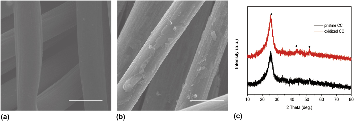
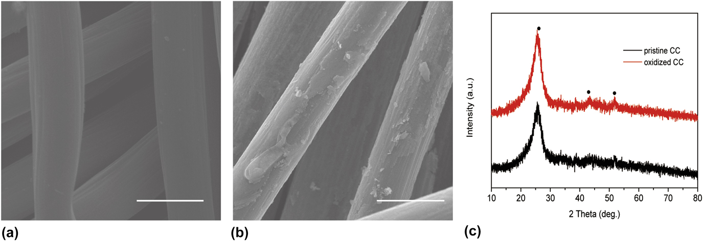
Before the synthesized process, the carbon cloth was oxidized in a mixed solution containing concentrated H2SO4 and HNO3 (V/V = 1:1) for 40 min to produce porous surface with abundant oxygen groups. These abundant surface oxygen groups and rough surface will also help the nucleation of Co(OH)F on the CC. As shown in Fig. 1(a), the SEM image revealed that the fibers of the carbon cloth before acid oxidation were very smooth. The diameter of these carbon fibers was around 6 μm. It should be noted that the carbon cloth was made up with a mass of interlaced microfibers. This open interspace and special structures of the carbon cloth were beneficial for high mass transfer between the electrode and the solution and the release of oxygen bubbles. On the other hand, as illustrated in Fig. 1(b), the surface of carbon fibers became rough after oxidation in mixed acidic solution for 40 min, and lots of small protrusions with different diameters were observed. The diameter of these oxidized carbon fibers were still around 6 um, which indicated that the mild oxidation condition in mixed acidic solution would only oxidize the surface carbon and bring abundant oxygen groups. Moreover, the special open interspace and structures remained after acidic oxidation, which meant that the high mass transfer between the electrode and solution would also be achieved. In addition, the abundant oxygen groups and rough surface of carbon fibers were in favor of the growth of following Co(OH)F nanosheets. XRD patterns of pristine carbon cloth and oxidized carbon cloth were also collected to analyze the main composition of these samples. As shown in Fig. 1(c), only three obvious peaks were observed. The peaks of oxidized carbon cloth located at the same diffraction angles of pristine carbon cloth. In general, the broad peaks at ∼22°, ∼43°, and ∼52° can be assigned to the amorphous carbon from carbon cloth. No other impurity peaks were detected, indicating that the samples were very pure. Therefore, the XRD spectra showed that the acidic oxidation process has no apparent change of composition of the carbon cloth.
SEM images of (a) pristine carbon cloth and (b) oxidized carbon cloth. (c) XRD patterns of pristine carbon cloth and oxidized carbon cloth.
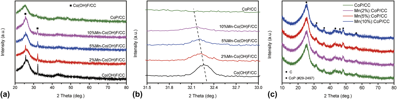
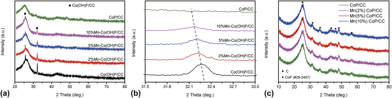
The XRD patterns in Fig. 2(a) revealed that the main composition of the as-prepared samples was Co(OH)F after the hydrothermal process. The two obvious diffraction peaks at 25.68° and 32.30° can be assigned to the planes of (210) and (310) of Co(OH)F (JCPDS #50-0827), respectively. The broad peaks at ∼22° and ∼43° can be assigned to the amorphous carbon from the carbon cloth, which has been discussed above. More importantly, it should be pointed out that the peaks of Co(OH)F shifted to lower diffraction angles after doping with the Mn element, as shown in Fig. 2(b). According to the Bragg equation (3),
 $$2d\sin \theta = n\lambda \quad ,$$
where d is the lattice distance of the crystal, θ is the diffraction angle, n is the diffraction order, and λ is the Cu Kα radiation wave length (λ = 0.15418 nm); a smaller lattice distance will be obtained when the diffraction angle θ shifts to higher diffraction angles. In this case, the ionic radius of Mn2+ ions (67 pm) is a little larger than that of Co2+ ions (65 pm).Reference Haynes29 As a result, the d of CoP will become larger when Mn2+ ions are incorporated into the CoP lattice and hence lead to a shift to lower diffraction angles. Therefore, the Mn element has been successfully incorporated into Co(OH)F lattices since the peaks of Co(OH)F shift to lower diffraction angles. After annealing the precursors of Mn doped Co(OH)F with NaH2PO2 under Ar atmosphere at 350 °C for 2 h, obvious peaks at 31.6°, 35.3°, 36.3°, 46.2°, 48.1°, 52.3°, 56.1°, and 56.8° as shown in Fig. 2(c) were observed, which can be assigned to the planes of (011), (200), (111), (112), (211), (103), (020), and (301) of CoP (JCPDS #29-0497), respectively. These results meant that the Co(OH)F nanosheets transformed into CoP nanosheets under the annealed process. Besides these observed peaks, there were no other distinct peaks, indicating the high purity of these CoP electrode materials. Moreover, the doping amount of Mn has no obvious effect on the composition and structures of Mn–CoP/CC.
XRD patterns of (a) as-prepared Co(OH)F/CC and different Mn–Co(OH)F/CC. (b) Enlarged XRD spectra of the Co(OH)F/CC and Mn–Co(OH)F/CC between the diffraction angles 31.5° and 33.0°. (c) XRD patterns of CoP/CC and different doping Mn–Co(OH)F/CC.
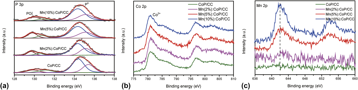
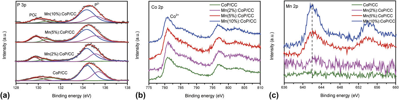
The XPS spectra were further conducted to analyze the surface chemical composition and valence states of the as-prepared CoP/CC and Mn doped CoP/CC electrode materials. Figure 3(a) showed two sharp peaks in the P 2p region from the binding energy between 128.0 and 138.0 eV, indicating that there were disparate valence states of P. Each sharp peak in P 2p can be disintegrated into two peaks of P 2p3 and P 3p1, and the results were shown in Fig. 3(a). The peak at a binding energy of 134.6 eV can be assigned to phosphide (metal–P bond), while the peak at a binding energy of 129.8 eV can be assigned to phosphite (metal–POx bonds).Reference Li, Baydoun, Verani and Brock18,Reference Zhai, Wan, Sun, Chen, Sun, Xia and Xia30,Reference Tang, Zhang, Lu, He, Jiang, Asiri and Sun31 Therefore, these results demonstrated that there were both phosphide and phosphite in the as-prepared CoP/CC and Mn doped CoP/CC electrodes. In general, the peak intensity of the phosphide was much stronger than that of the phosphite, indicating that only small part of the surface phosphide oxidized into phosphite. Two sharp peaks in the Co 2p region from the binding energy between 775.0 and 811.0 eV, indicating that there were Co in the as-prepared CoP/CC and Mn doped CoP/CC electrodes. The typical value of Co 2p was centered at the binding energies of ∼780.8 and ∼797.0 eV [Fig. 3(b)], which can all be assigned to Co(II). It can be concluded that CoP was synthesized successfully by considering the XPS peaks of both Co(II) and P. On the other hand, as shown in Fig. 3(c), the peak in the Mn 2p region from the binding energy between 636.0 and 660.0 eV of CoP/CC was almost negligible. However, a very but obvious peak at 642.0 eV of Mn(II)Reference Li, Baydoun, Verani and Brock18 can be detected after doping with the Mn element of 2% ratio. More importantly, the peak intensity of these Mn(II) increased with the doping amount of the Mn element. Then, with a higher doping amount of the Mn element of 5% ratio, the Mn(II) peak at 642.0 eV was much stronger than the Mn(2%)–CoP/CC. At last, the Mn(10%)–CoP/CC showed the highest peak of Mn. These results demonstrated that the Mn element was successfully doped into the lattices of CoP, which is in accordance with the XRD spectra.
XPS core level spectra of (a) P 3p, (b) Co 2p, and (c) Mn 2p for the CoP/CC and all Mn–CoP/CC.
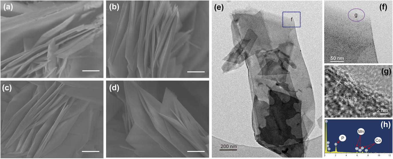
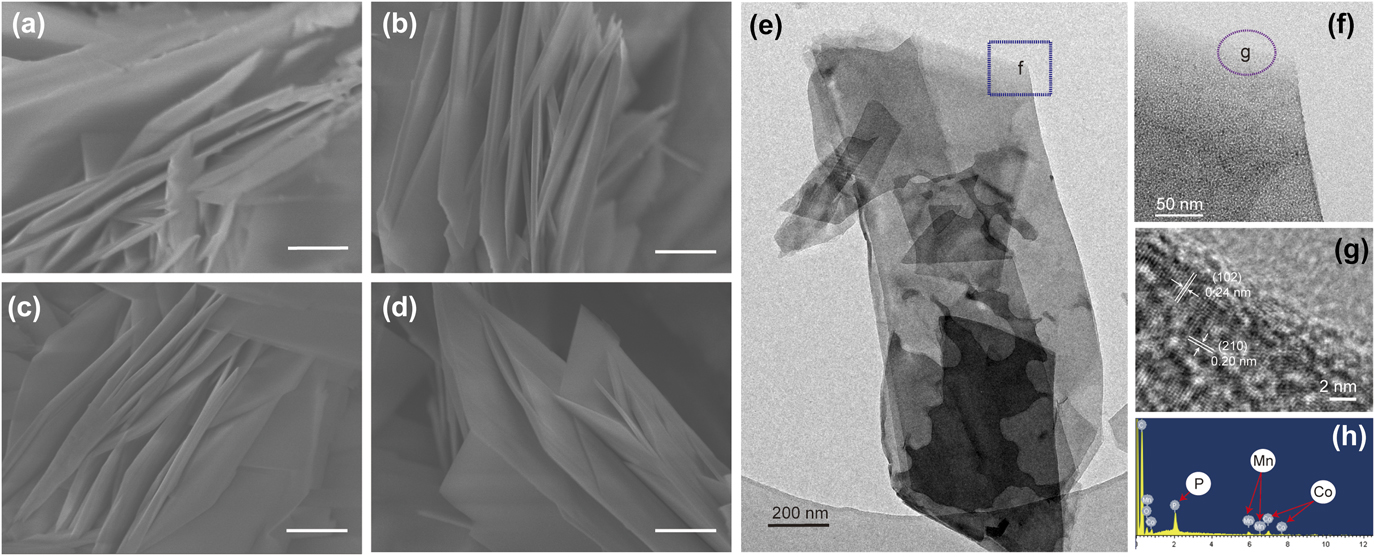
FE-SEM images of these Mn doped CoP/CC were also collected, which revealed that all the samples have morphology of nanosheets with a thickness of around 100 nm. The length of the Mn doped CoP/CC nanosheets was around 1.4 μm, and the width of these materials was around 500 nm, too. As illustrated in Figs. 4(a)–4(d), the doping amount of Mn elements has no obvious influence upon the morphology, the length, and the width of these materials. Moreover, the special open interspace and structures of all the Mn doped CoP/CC electrodes remained after being coated with different Mn doped CoP nanosheet arrays, which meant that the high mass transfer between the electrode and solution would also be achieved. TEM analyses were performed to study the micro-structures of the Mn(5%)–CoP/CC. The typical TEM image in Fig. 4(e) also showed that the morphologies of Mn(5%)–CoP/CC were nanosheets. It showed that a single nanosheet possessed a width of 600 nm and a length of 1.4 μm, which was close to the SEM images. It should be pointed out that some nanosheets were broken by ultrasonication during the TEM sample preparation process. To further obtain the detailed structure information, the HR-TEM images of the selected area marked in Fig. 4(e) were illustrated in Figs. 4(f) and 4(g). As shown in Fig. 4(g), the lattice fringes of 0.24 and 0.20 nm were clearly observed, which were consistent with the (102) plane and (002) plane of CoP, respectively. Therefore, it can be concluded that CoP was synthesized successfully. In addition, the energy dispersive X-ray spectroscopy (EDS) analysis was also conducted from the selected area of the nanosheet, and the result was displayed in Fig. 4(h). Only C, P, Co, Mn, and Cu were observed in the EDS pattern. Besides the Cu signals originated from the Cu grid (for TEM measurement) and the C signals came from the residual carbon cloth fibers, and no other signals were detected. Thus, this result again confirmed that the nanosheet was composed of CoP with doping Mn element and the high purity of the Mn doped CoP materials.
SEM images of (a) CoP/CC, (b) Mn(2%)–CoP/CC, (c) Mn(5%)–CoP/CC, and (d) Mn(10%)–CoP/CC. The scale bars in figures are 500 nm. (e, f) TEM images, (g) HR-TEM image, and (h) energy-dispersive X-ray (EDX) spectrum of the Mn(5%)–CoP/CC.
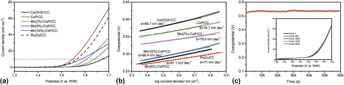
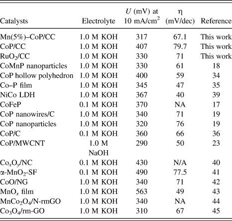
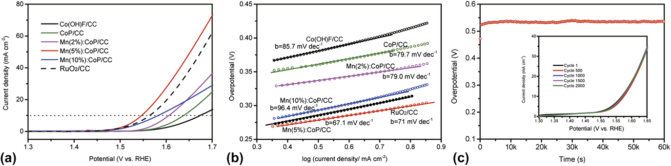
The OER activity of the as-prepared RuO2/CC, Co(OH)F/CC, CoP/CC, and different Mn amount doped CoP/CC electrodes were tested in a solution of 1 mol/L KOH at the scan rate of 2 mV/s, and the results were summarized in Fig. 5(a). Obviously, the current densities of all electrodes increased with the applied potential, and different electrodes had different onset potentials/overpotentials and current densities toward water oxidation. As mentioned above, the noble metal oxide electrode, the RuO2/CC electrode, showed a remarkable electrocatalytic activity for water splitting. The current density of the RuO2/CC electrode can be up to 42.7 mA/cm2 at 1.70 V versus RHE. It also achieved an overpotential of around 330 mV to reach the current density of 10 mA/cm2. However, the pristine Co(OH)F/CC showed negligible current at the potential between 1.50 and 1.60 V versus RHE. Then, with further increasing the applied potential, the current density rose dramatically. The current density at 1.70 V versus RHE was only around 13.7 mA/cm2. It needs the overpotential of about 433 mV to achieve the current density of 10 mA/cm2, which was dissatisfactory for the practical application with such low current density and large overpotential. Compared to the pristine Co(OH)F/CC, the electrolytic current of the CoP/CC electrode increased with the applied potential simultaneously in the electrochemical windows from 1.6 V to 1.7 versus RHE, and the current density was around 24.9 mA/cm2 at 1.70 V versus RHE. The CoP/CC electrode showed an enhanced OER activity with an overpotential of around 407 mV to reach the current density of 10 mA/cm2, which has been widely proved by recent studies.Reference Wu, Pi, Zhang and Chen32–Reference Liu and Li34 Significantly, after doping with the Mn element, it was clearly found that the Mn(2%)–CoP/CC electrode had the current density around 36.4 mA/cm2 at 1.70 V versus RHE, which was much larger than that of the pristine CoP/CC electrode. Significantly, the Mn(2%)–CoP/CC electrode achieved a lower overpotential (376 mV) to reach the current density of 10 mA/cm2, indicating the doping Mn element can somehow further improve the ability of traditional CoP for OER. However, both the electrolytic current and the overpotential at 10 mA/cm2 were still inferior to the RuO2/CC electrode. Then, with higher doping amount of Mn element, the Mn(5%)–CoP/CC electrode demanded the overpotential of 317 mV to reach the electrocatalytic current density of 10 mA/cm2. This value was smaller than that of CoP/CC, Mn(2%)–CoP/CC, and RuO2/CC electrodes. More importantly, the Mn(5%)–CoP/CC electrode achieved a current density of 72.8 mA/cm2 at 1.70 V versus RHE, which was also larger than that of CoP/CC, Mn(2%)–CoP/CC, and RuO2/CC electrodes. It was worthy to note that the amazing electrocatalytic performance was also close to or better than the recently reported cobalt or CoP-based catalysts, which have been listed in Table I, for example, CoMnP nanoparticles (1.0 mol/L KOH, 330 mV, 61 mV/dec),Reference Li, Baydoun, Verani and Brock18 CoP hollow polyhedron (1.0 mol/L KOH, 400 mV, 59 mV/dec),Reference Liu and Li34 Co–P film (1.0 mol/L KOH, 345 mV, 47 mV/dec),Reference Jiang, You, Sheng and Sun35 CoP nanowires/C (1.0 mol/L KOH, 340 mV, 71 mV/dec),Reference Chang, Xiao, Xiao, Ge, Liu and Xing19 CoP nanoparticles (1.0 mol/L KOH, 320 mV, 76 mV/dec),Reference Chang, Xiao, Xiao, Ge, Liu and Xing19 and CoP/C (0.1 mol/L KOH, 360 mV, 66 mV/dec).Reference Ryu, Jung, Jang, Kim and Yoo36 However, if the doping concentration of the Mn element further increased, the electrocatalytic performance decreased. The Mn(10%)–CoP/CC electrode only achieved a current density of around 29.0 mA/cm2 at 1.70 V versus RHE. This value was much smaller than both the Mn(5%)–CoP/CC electrode and RuO2/CC electrode and even smaller than the Mn(2%)–CoP/CC electrode. The Mn(10%)–CoP/CC electrode also needs the overpotential of 353 mV to reach the current density of 10 mA/cm2. Although this performance was still better than the pristine CoP/CC and Mn(2%)–CoP/CC electrode, it was still smaller than both the Mn(5%)–CoP/CC electrode and RuO2/CC electrode. Therefore, a high doping amount of the Mn element (10%) leads to decreased OER activity.
(a) IR-corrected polarization curves and (b) Tafel plots of RuO2/CC, Co(OH)F/CC, CoP/CC, and different Mn amount doped CoP/CC electrodes at the scan rate of 2 mV/s for OER. (c) Long-term stability test of Mn(5%)–CoP/CC electrode carried out under a constant current density of 10 mA/cm2. The inset was the iR-corrected polarization curves for Mn(5%)–CoP/CC electrode before and after 500, 1000, 1500, and 2000 cyclic voltammetry. All experiments were done in a solution of 1 mol/L KOH.
Electrochemical catalytic performance of some representative solid-state catalysts under alkaline medium recently reported. The symbol of U in the table refers to the overpotential at the applied current density; η refers to the Tafel slope.

On the other hand, the Tafel slope was another key factor to analyze the electrolytic activity of the Mn doped CoP/CC electrodes. By assuming a linear dependence between the log-current and the overpotential for the electrochemical reaction, the Tafel plots can illustrate the inherent property of multi-step electrocatalytic reactions between the solid electrode and the electrolyte. Figure 5(b) illustrated the Tafel plots of as-prepared RuO2/CC, Co(OH)F/CC, CoP/CC, and different Mn amount doped CoP/CC electrodes, which fitted from the Tafel equation (4)
 $$\eta = a + b\log j\quad ,$$
where b is the Tafel slope and j is the current density of the Mn doped CoP/CC electrodes and RuO2/CC electrode. Here, the RuO2/CC showed a Tafel slope of 71 mV/dec, which was close to the recentReference Varcoe and Slade37,Reference Chen, Wang, Wang, Zhou, Wu and Jiang38 reports. The Co(OH)F/CC electrode had a Tafel slope of 85.7 mV/dec, which was much larger than the RuO2/CC electrode. In comparison, the CoP/CC electrode had a small value, with the Tafel slope of 79.7 mV/dec. After doping with Mn element, the Mn(2%)–CoP/CC electrode achieved a Tafel slope of around 79.0 mV/dec, demonstrating that the doping Mn can enhance the electrocatalytic performance of water oxidation. More importantly, the Tafel slope for Mn(5%)–CoP/CC was ∼67.1 mV/dec, which was much smaller than that of electrodes mentioned above, indicating much more efficient activity of oxygen generation. Similarly, with higher doping amount, the Tafel slope of Mn(10%)–CoP/CC decreased dramatically to 96.4 mV/dec, which was also larger than the Mn(2%)–CoP/CC, Mn(5%)–CoP/CC electrode, and RuO2/CC electrode and even inferior to that of the Co(OH)F/CC electrode and CoP/CC electrode. Therefore, the Mn(5%)–CoP/CC electrode exhibited the best electrocatalytic activity toward water oxidation among the different Mn doped CoP/CC electrodes.
Besides the high activity toward water splitting, the long-term stability is another important factor for the OER catalysts. To evaluate the long-term stability of the as-prepared Mn(5%)–CoP/CC, long-term anodic constant current with the density of 10 mA/cm2 and cyclic voltammetry of 2000 cycles were also adopted, and the results were shown in Fig. 5(c). The Mn(5%)–CoP/CC electrode performed long-term electrochemical stability for water electrolysis over a period of 16 h with the constant current density of 10 mA/cm2. Besides the long-term constant current measurement, cyclic stability was also recorded by cyclic voltammetry between the potential 1.3 and 1.8 V versus RHE for 2000 cycles with a scan rate of 10 mV/s. The inset in Fig. 5(c) clearly showed that it still performed as well as the 1st cycle after 500, 1000, 1500, and 2000 voltammetry cycles, with negligible loss of anodic current density. These results demonstrated that the Mn(5%)–CoP/CC electrode was very stable for the long-term water splitting. Thus novel stability during long time and cycles made it one of the most promising candidates for the OER catalysts.
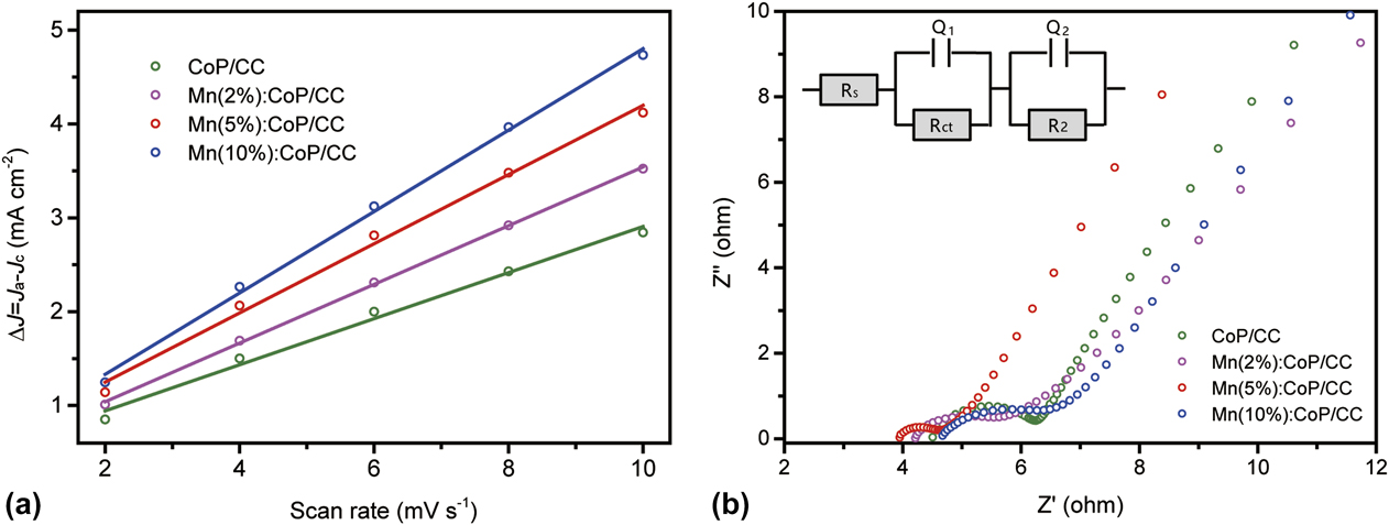
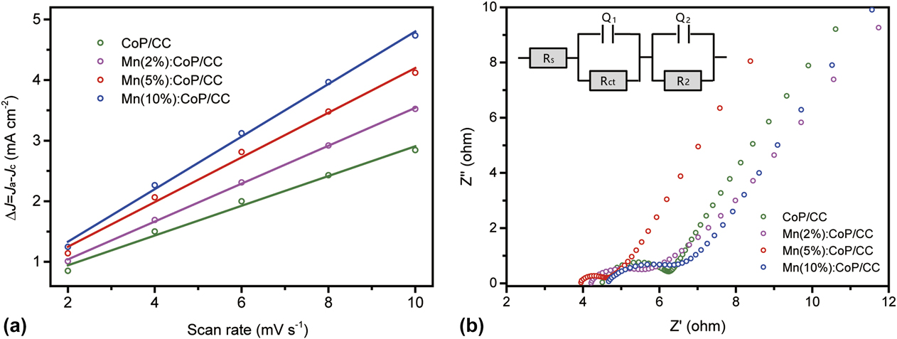
As discussed above, the 3D structures of CC are beneficial for high electrocatalytic performance due to the intrinsic large specific surface area and high mass transfer between the catalyst and the solution. The CoP/CC and Mn doped CoP/CC electrodes here showed an outstanding water splitting activity compared to the RuO2/CC electrode or other CoP/cobalt-based OER catalysts. However, the activity of the CoP/CC electrode, Mn(2%)–CoP/CC electrode, and Mn(10%)–CoP/CC electrode was still inferior to that of the Mn(5%)–CoP/CC electrode. Therefore, thus outstanding enhanced electrochemical activity originated from other factors. Cyclic voltammetry was conducted to study the electrochemical double-layer capacitance (C dl) at different scan rates during a narrow potential from 1.10 to 1.25 V versus RHE, and the results were summarized in Fig. 6(a). As mentioned in Sec. II, the electrochemical double-layer capacitance (C dl) of the OER catalysts had a linear relationship of the surface charging current density differences (ΔJ = J a − J c) plotted against scan rates. A high surface electrochemical area would be achieved with a larger slope of the OER catalysts. After the calculation, it can be found that the CoP/CC electrode has the capacitance of 246 mF/cm2. However, after doping with the Mn element, the Mn(2%)–CoP/CC electrode showed a surface capacitance of 313 mF/cm2, which was much larger than that of the pristine CoP/CC electrode. On the other hand, the capacitance of the Mn(5%)–CoP/CC electrode further increased to 368 mF/cm2. Therefore, the Mn(5%)–CoP/CC electrode showed superior water oxidation performance than both the CoP/CC electrode and Mn(2%)–CoP/CC electrode, indicating that the higher surface electrochemical areas would make a contribution to the excellent electrocatalytic activity. On the other hand, the Mn(10%)–CoP/CC electrode had the largest surface capacitance of around 434 mF/cm2. Therefore, the surface capacitance or the surface areas can be increased with the doping amount of Mn element simultaneously. Although the surface capacitance of the Mn(10%)–CoP/CC electrode was larger than the Mn(5%)–CoP/CC electrode, the Mn(10%)–CoP/CC electrode only achieved a current density of around 29.0 mA/cm2 at 1.70 V versus RHE. This value was much smaller than both the Mn(5%)–CoP/CC electrode and RuO2/CC electrode and even smaller than the Mn(2%)–CoP/CC electrode. As a consequence, considering that the Mn(5%)–CoP/CC electrode possessed superior water splitting activity than the Mn(10%)–CoP/CC electrode, it indicated that the surface areas only made little contribution to its outstanding OER activity. To further understand the enhanced charge-transfer property of the Mn–CoP/CC electrodes, electrochemical impedance spectroscopy (EIS) was also conducted at the onset potential of each electrode. Two equivalent circuits were used to fit the measured Nyquist plots of the as-prepared CoP/CC and Mn doped CoP/CC electrodes. As shown in Fig. 6(b), the Mn(5%)–CoP/CC electrode possess the smallest charge transfer resistance compared to other Mn doped CoP/CC and pristine CoP/CC electrodes. Therefore, the superior activity of the Mn(5%)–CoP/CC electrode mainly arises from effective charge-transfer by the doping Mn element.
(a) Surface charging current density differences (ΔJ = J a − J c) plotted against scan rates and (b) the Nyquist plot of CoP/CC and different Mn doped CoP/CC electrodes in 1.0 mol/L KOH electrolyte measured at the onset potential.
In summary, the pristine carbon cloth was first oxidized in a mixed solution containing concentrated H2SO4 and HNO3 to produce porous surface with abundant oxygen groups. These abundant surface oxygen groups and rough surface will also help the nucleation of the Mn doped Co(OH)F on the CC. The XRD spectra and SEM and TEM images showed that the as-prepared Mn doped Co(OH)F nanosheets transformed successfully into CoP nanosheets after being annealed with NaH2PO2 powder. Moreover, the doping amount of Mn has no obvious effect on the composition and structures of Mn–CoP/CC. Compared to the pristine Co(OH)F/CC and CoP/CC electrodes, the Mn doped CoP/CC electrodes exhibited significantly improved activity with higher water splitting current densities and lower Tafel slopes. Specially, the Mn(5%)–CoP/CC electrode demands an overpotential of 317 mV to reach the electrocatalytic current density of 10 mA/cm2, with the Tafel slope of ∼67.1 mV/dec. This value is even substantial or better than the recently reported cobalt or CoP-based catalysts. Moreover, the Mn(5%)–CoP/CC electrode also showed long-term stability toward the OER. A systematic study reveals that the superior activity of the Mn(5%)–CoP/CC arises from effective charge-transfer and increased surface areas by the doping Mn element. Here this doping method can open our mind in developing the next-generation sustainable electrocatalysts for water splitting with outstanding activity and durability.
ACKNOWLEDGMENTS
This work was supported by National Natural Science Foundation of China (Nos. 21375016, 21475022, and 21505019), the Natural Science Foundation of Guangdong Province (No. 2015A030310272), Technology Planning Project of Guangdong Province (No. 2015B090927007), Guangdong Provincial Key Platform and Major Scientific Research Projects for Colleges and Universities (No. 2014KZDXM073, 2015KCXTD029, and 2016KQNCX166), and Guangdong Province key platforms and projects of Guangdong Universities (No. 2015KQNCX161).