I. INTRODUCTION
In recent years, aluminum honeycomb materials have attracted a great deal of attention owing to their outstanding advantages such as high energy absorption capacity, good thermal insulation, light weight, and high strength. Reference Hu, You and Yu1 These advantages of aluminum honeycomb materials mainly depend on the continuous multiwall arrangement of the honeycomb. The hexagonal network structure can distract the external force from all directions, and thus makes its resistance to impact load much higher than other structures. Reference Yahaya, Ruan, Lu and Dargusch2 Under dynamic impact load, it can bear large plastic deformation to absorb high energy. Reference Ashab, Ruan, Lu, Xu and Wen3 Owing to this characteristic, aluminum honeycomb sandwich panel with aluminum honeycomb core has been identified as one potential energy absorption protective material that can be widely used in different industry fields, such as aerospace, automotive, architecture, shipping, transportation, and so on. Reference Ashaby, Wong, Lu and Ruan4–Reference Yanchang and Zili8 Therefore, it is very necessary to gain a better knowledge of its mechanical properties especially the dynamic mechanical property so as to get a correct understanding of the applications of this material in different areas.
The mechanical behaviors of aluminum honeycomb under dynamic load have been extensively investigated by both experimental and numerical studies. Through the quasistatic and dynamic impact tests, Ashab et al. Reference Ashab, Ruan, Lu and Wong9 tested three types of hexagonal aluminum honeycomb under five different velocities. They presented the displacement, impact force, plateau stress, and energy absorption of aluminum honeycomb based on experimental results, and analyzed the loading plane, loading velocity, and loading angle. Yasui et al. Reference Yasui10 carried out the dynamic impact test on multi-layer honeycomb panels, and the results indicated that the behaviors of these materials were influenced sensitively by dynamic impact velocity and material mechanical properties. Ude et al. Reference Ude, Ariffin and Azhari11 investigated the impact toughness of light weight sandwich panels with reinforced composite surface and aluminum honeycomb core. They analyzed the degree of damage inflicted on the contact surface, penetration thickness, and rear surface, and explored the bearing capacity, energy absorption capacity, and failure modes of the sandwich panels under different impact energies. Hazizan Reference Hazizan and Cantwell12 tested two types of aluminum honeycomb sandwich panels by carrying out drop-weight impact test. The strain rate sensitivity of the sandwich panels was analyzed, and an energy absorption model of aluminum honeycomb structures was constructed to explain the energy absorption in bending and shear tests. Hong et al. Reference Hong, Pan, Tyan and Prasad13 tested different types of aluminum honeycomb by carrying out dynamic impact test under inclined loads. The results showed that the normal crush strength increased while the shear strength remained basically unchanged with the increase of impact velocity. Zhao et al. Reference Zhao, Elnasri and Abdennadher14 conducted dynamic impact test on aluminum honeycomb with various cell sizes and wall thicknesses. The strain rate sensitivity was found to have a great effect on aluminum honeycomb, and the reason for generating this effect was analyzed. Li et al. Reference Li, Zhang, Wang, Wu and Zhao15 studied the mechanical properties of aluminum honeycomb sandwich panels under air blast, and the scaled distance of the explosive was considered as the main reason for failure modes of the composite surface. Chi et al. Reference Chi, Langdon and Nurick16 studied the behaviors of circular sandwich panels with aluminum honeycomb core under air blast loading. It was found that the increase of core thickness delayed the onset of core densification and decreased the deflection of back plate. Deng et al. Reference Lei, Anwen, Liuwei and Kuibin17 analyzed the deformation mechanism and energy absorption characteristics of a square-hole honeycomb sandwich plate under blast loading by the finite element numerical simulation method. They found that there existed an optimal core relative density sandwich plate that endowed the core with the highest energy absorption rate. This corresponded to the minimum deflection in the bottom face sheet and the optimal shock resistance of the structure. Li et al. Reference Li, Gao and Wang18 analyzed the impact response of honeycomb structure with irregular cell shapes and nonuniform cell wall thickness. They investigated the plateau stress, initial strain, and energy absorption by using the finite element method, and summarized different failure models according to the experimental results. For the purpose of better understanding the aluminum honeycomb energy absorption capacity under dynamic load, Xie et al. Reference Xie and Zhou19 carried out numerical analysis on three different types of aluminum honeycomb using the ANSYS finite element method, and the results indicated that the dominant deformation mechanism of aluminum honeycomb under dynamic impact load was stage-by-stage deformation. Hönig et al. Reference Hönig and Stronge20 investigated the in-plane impact on honeycomb by using finite element simulations and analyzed the dynamics of impact band initiation and wave trapping under two different boundary conditions. The simulations proved that elastic wave propagation had an important effect on crush band initiation.
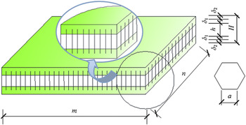
Aluminum honeycomb sandwich panel is mainly composed of two metallic or other panels and an aluminum honeycomb core. The panels usually have high strength and stiffness, while the core with large deformation capacity can absorb a lot of energy. Thus, the structure can be protected from being damaged when the sandwich panel is subjected to impact and blast loads. According to Ref. Reference Cheng, Zhao, Xin, Du and Li21, a new method of manufacturing aluminum honeycomb sandwich panel was proposed, which was different from that of manufacturing traditional sandwich panel. Reference Minxi and Junmin22,Reference Min and Changjun23 The face sheets of the sandwich panel are composite that consists of aluminum honeycomb-resins to replace simple metals, and aluminum honeycomb is gripped between the face sheets. Thus, the core and surface can be combined together without obvious interface (Fig. 1).
Schematic diagram of the specimen. Notes: H is the specimen’s height, δ1 is the immersed resin thickness, δ2 is the additional layers’ thicknesses, h is the core’s thickness, m and n are the lengths of specimen edges.

Based on the productive process of this type of composite sandwich panel, the present paper examines the dynamic behaviors of the integrated panel by employing drop-weight impact test. The dynamic mechanical properties are discussed through varying the impact velocity and impactor shape, and the typical curves are summarized under different impactor shapes. On this basis, failure modes of the panel are analyzed by observing the results of drop-weight impact test.
II. EXPERIMENTAL
A. Materials and properties
The main material is hexagon aluminum honeycomb of 0.05 mm in cell wall thickness. It has good flatness, high strength, low density, and high shear resistance. DY.E44 resin and DY.EP resin firming agent are chosen as auxiliary materials to manufacture the composite.
B. Manufacturing
Reference Reference Cheng, Zhao, Xin, Du and Li21 provides the detailed manufacturing method. Firstly, the epoxy resin was completely poured into the mold of a specified thickness. Secondly, the processed aluminum honeycomb sandwich panel was placed into the mold slowly and stably. Thirdly, the resin was solidified for three days at ambient temperature, and then excessive resin at the edge of the aluminum honeycomb was removed. The other side of the aluminum honeycomb sandwich panel was prepared using the same process. Finally, each specimen was coded with numbers for further use.
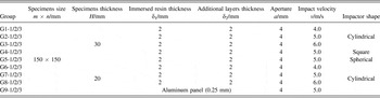
The dynamic mechanical properties of the integrated composite sandwich panel were investigated by drop-weight dynamic impact test through varying impact velocity and impactor shape. To ensure the accuracy of experiment results, each group had three replicates. The testing parameters and specimen numbers are shown in Table I.
Specimen number and parameter.

C. Impact testing system
The drop-weight impact test was carried out on an INSTRON CEAST 9350 impact testing system (Instron, Torino, Italy). This system contains a drop tower equipped with an impactor that can vary the balance weight, and a high speed data acquisition system is also equipped to obtain different data during the test. A force sensor was connected with the impactor. To avoid multiple strikes, the drop-weight impact tester was also equipped with a pneumatic break. The integrated sandwich panels were tested at an impact energy of 100 J, and the impact velocities were 4 m/s, 5 m/s, and 6 m/s respectively. In these tests, two kinds of impactor were designed referring to the cross section size in Ref. Reference Cheng, Zhao, Xin, Du and Li21, and the length of all impactors was made as 80 mm so as to protect the force sensor.
The supporting frame was designed as the same sizes as those in Ref. Reference Cheng, Zhao, Xin, Du and Li21. The specimens were bolted between the supporting frame and pressing panel under fully fixed boundary conditions. Another rigid panel with a diameter of 200 mm was designed. The rigid panel was welded together with the frame and then put into the apparatus. The frame height was set as 130 mm to install the cushion appliance to prevent impact failure problems.
III. IMPACT RESULTS
A. Failure behaviors
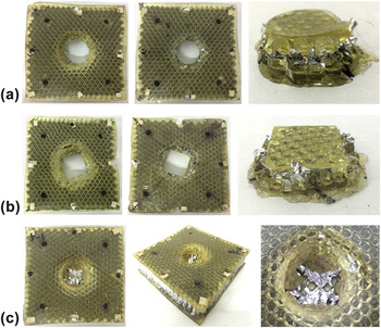
In the drop-weight impact test, the specimens were put on the frame and fixed by bolt, and the impactor was connected with the force sensor. The impact test was conducted at impact velocities of 4 m/s, 5 m/s, and 6 m/s respectively. It can be found from the impact test results that the integrated composite sandwich panel of aluminum honeycomb and epoxy resin maintains a good stability and integrality during the impact test. Under dynamic impact load, the composite layer is not separated from core material. The damage of the composite sandwich panel on the upper surface manifests as cracking near the impactor, and the crack shape is similar to the impactor shape. For the flat-bottom impactor, the bottom surface of composite sandwich panel is penetrated, and the materials under the impactor are separated from the core. The aluminum honeycomb core materials are squashed layer by layer to densification, and the area of bottom face is larger than that of impactor [Figs. 2(a) and 2(b)]. For the gradual impactor, the bottom surface of the composite sandwich panel is not penetrated, and the impactor just presses into the specimen instead of tearing it [Fig. 2(c)].
Damage pictures with different impactors. (a) Damage pictures with cylindrical impactor. (b) Damage pictures with square impactor. (c) Damage pictures with spherical impactor.

B. Typical force–deformation curve
1. Flat-bottom impactor shape (cylindrical indenter and square indenter)
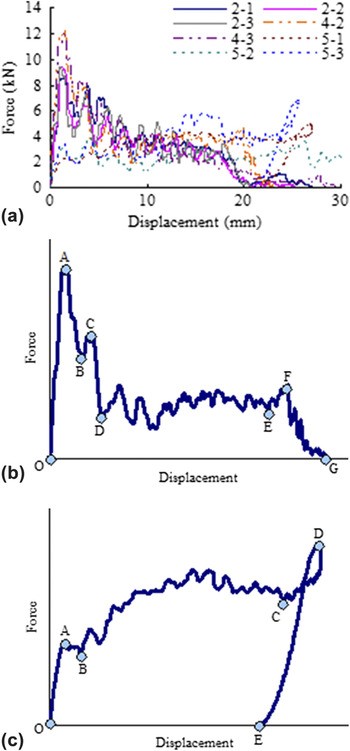
Figure 3 shows the measured force–displacement curves of the specimens under different types of impactor, from which typical force–displacement curve of the flat-bottom impactor shape can be summarized as shown in Fig. 3(b). It can be seen that the curve has seven characteristic phases.
Force–displacement curves with different impactors and typical curves.

Linear elastic phase (O–A): The force–displacement curve exhibits a linear increase at the beginning, and the load keeps increasing until it reaches the maximum force at point A. Responding to this phase, inner and outer deformations of the specimen are not changed.
Local damage phase (A–B): Once the load reaches the maximum force, there is a sudden drop of the load due to the cracking in the upper composite layer, which leads to the decrease of the load to point B.
Global stress phase (B–C): With the increase of displacement, most of the load is transferred to aluminum honeycomb cell walls. Thus, cell walls and upper composite layer can bear load together, which results in the slight increase of the load to point C.
Upper surface damage phase (C–D): With further increase of displacement, the upper composite ruptures along the edge of the impactor, and the material beneath the impactor is separated from upper composite layer. Consequently, the load drops suddenly to point D.
Plateau phase (D–E): With further increase of displacement, the load presents a plateau oscillating phase, and the aluminum honeycomb cell walls under the impactor are squashed layer by layer.
Densification phase (E–F): Aluminum honeycomb cell walls are densified after the plateau phase, so that most of the load is transferred to the bottom surface, which results in the slight increase of the load to point F.
Bottom damage phase (F–G): With the increase of displacement, the lower composite layer is damaged, and the specimen is penetrated. The suddenly decreased load represents the failure of the specimens.
2. Gradual impactor (spherical impactor)
Figure 3(c) shows the typical curve of the gradual impactor shape obtained from the measured force–displacement curves in Fig. 3(a). It can be seen that the curve has five characteristic phases.
Linear elastic phase (O–A): This phase is similar to that of the flat-bottom impactor. With the increase of displacement, the load increases linearly until it reaches point A. However, since the spherical impactor has a gradually increasing cross section area, its contact area with the specimens is small at the beginning, which results in a shorter duration of this phase compared with the flat-bottom impactor.
Local damage phase (A–B): The spherical impactor gradually crushes into the specimen, so the upper composite surface has no obvious crack [Fig. 3(c)]. The load in this phase basically keeps unchanged.
Plateau rising phase (B–C): With the increase of displacement, the zone beneath the impactor is squashed layer by layer, and the crushed areas of the upper composite layer and inner aluminum honeycomb cells expand gradually. That is why the load shows an increasing oscillation.
Densification phase (C–D): The load keeps rising to the maximum force at point D, and the aluminum honeycomb cell walls are squashed gradually, which represents the end of the test.
Rebound phase (D–E): The specimen is not penetrated, so the impactor rebounds from the impacted composite panel and is caught immediately by the pneumatic break to avoid multiple strikes.
IV. ANALYSIS
A. Influence of impact velocity
Three different impact velocities are designed to carry out the drop-weight impact test, and the testing groups of G1, G2, and G3 respectively correspond to the impact velocities of 4 m/s, 5 m/s, and 6 m/s.
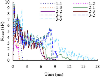
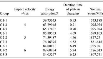
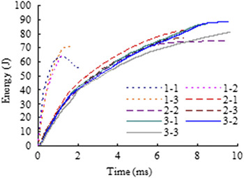
Figure 4 shows the force–time curves of the specimens at different impact velocities. Table II shows the Comparison for different velocity. As shown in Fig. 4, the plateau phase duration time of the integrated composite sandwich panel under different impact velocities is different. Combined with Table II, it can be found that the plateau phase duration time increases obviously with the increase of impact velocity. At the impact velocity of 4 m/s, the average plateau phase duration time is 0.71 ms; at the impact velocities of 5 m/s and 6 m/s, the average plateau phase duration times are 4.56 ms and 6.29 ms, respectively. It can be seen from Table II, with the increasing of the velocity, there is an obviously enhancement. When the velocity rising from 5 m/s to 6 m/s, stress increase smaller. By analyzing the destruction process, the aluminum honeycomb materials appear stress enhancement phenomena when this material under different velocity. It is mainly because of the different strain rate sensitivity of the aluminum honeycomb materials under different strain rate. When sandwich panel under impact force, the force dissipated by the aluminum honeycomb core material successive fold. It shows that the aluminum honeycomb material has superior energy absorption and protective property. Figure 5 shows the energy–time curves of the specimens at different impact velocities. As shown in Fig. 5, at the impact velocity of 4 m/s, the growth rate of energy absorption is higher than those of other groups. It is because that at this relative lower velocity, the mechanical properties of sandwich panel are inclined to the quasistatic mechanical property. The specimen will be destroyed earlier, without sufficient energy absorption. Although the specimen can absorb more impact energy, it is damaged so untimely that its total energy absorption is less than those of other two groups. The average energy absorption of G1 is only 63 J. The energy absorption at the impact velocities of 5 and 6 m/s has basically the same growth rate. At the impact velocity of 6 m/s, the average absorption energy is 85 J, which is 1.36 times of that of G1 and 1.09 times of that of G2.
Force–time curves of specimens with different velocity.

Comparison for different velocity.

Energy–time curves of specimens with different velocity.

To sum up, with the increase of impact velocity, the plateau phase duration time and the stress both show an increasing trend. The plateau phase duration time is an important factor that affects the energy absorption capacity of the composite sandwich. Thus, impact velocity has a great influence on the properties of the integrated composite sandwich panel.
B. Influence of impactor shape
Three groups of specimens, G2, G4, and G5, are designed for the drop-weight impact test with different impactors, including two flat-bottom impactors (cylindrical and square impactors) and one gradual impactor (spherical impactor).
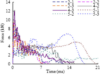
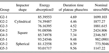
Figure 6 shows the force–time curves of the specimens with different impactors. It can be seen that the force–time curves of the specimens with cylindrical and square impactors are similar, but different from those of the specimens with spherical impactor. Table III shows the comparison for different impactor shape. It can be seen from picture, the spherical impactor has gradual cross section and acts on the specimens from point contact to surface contact, so that the contact area increases gradually. The core material around the impactor has not appears tearing failure, instead of the impactor extrusion destruction. While the core material around cylindrical and square impactors appears tearing failure, the destruction area of square impactor is bigger than the destruction area of cylindrical impactor. Thus, the spherical impactor impact duration time is longer than the others’, and the spherical impactor also has longer plateau phase duration time. On the contrary, the stress of the spherical impactor is much lower than other impactor shape. The stress of the square impactor is higher than other groups. It is because that the square impactor has edges that make the specimens generate strong shear section. It can be seen from Table III, the average plateau phase duration time of G5 is 9.52 ms, which is longer than those of G2 and G4. The growth rate of energy absorption for the spherical impactor is less than those for the cylindrical and square impactors; meanwhile, the spherical impactor can absorb more impact energy. It can be seen that there is little difference in energy absorption for different impactors.
Force–time curves of specimens with different impactor.

Comparison for different impactor shape.

To sum up, the stress of spherical impactor is lower than those of other types of impactor because of its gradual cross section, but it has larger deformation ability. Although impactor shape has little influence on the energy absorption capacity, it can affect the stress of the composite sandwich panel.
C. Influence of specimen thickness
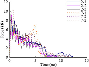
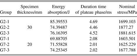
Two groups of specimens with different thicknesses (30 and 20 mm), G2 and G7, are designed for the drop-weight impact test with cylindrical impactor.
Figure 7 shows the force–time curves of the specimens, and Table IV shows the comparison for different specimen thickness. It can be seen that with the increase of specimen thickness, the plateau phase duration time also increases accordingly. The average plateau duration time of G2 is 4.56 ms, which is 2.24 times of that of G7. This is because that the deformation ability of the specimen decreases accordingly with the decrease of specimen thickness. The energy absorption growth rate of G2 is similar to that of G7, and the specimens absorb comparable energy during the same time. It can be seen from Table IV that the average energy absorption of G7 is slightly lower than that of G2. It can be seen from Table IV that with the increasing of the thickness of specimen, the stress of this sandwich panel has slightly increased.
Force–time curves of specimens with different specimen thickness.

Comparison for different specimen thickness.

D. Comparison with traditional sandwich panel
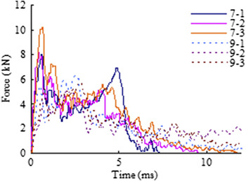
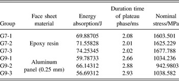
A traditional sandwich panel is prepared using aluminum panels of 0.25 mm in thickness with epoxy resin as adhesive. Then, drop-weight impact testis carried out on the traditional sandwich panel, and the results (G9) are compared with those of the integrated composite sandwich panel (G6) under the same test conditions.
Figure 8 shows the force–time curves of the composite and traditional sandwich panels, and Table V shows the comparison for composite and traditional sandwich panels. During the impact test, wrinkles appear around the upper surface of traditional sandwich panel, and cracks emerge in the aluminum panel under the impactor. As the impact test goes on, peeling-off phenomenon occurs between the lower aluminum panel and the core, which leads to early failure of the specimen. The energy absorption growth rate of the composite sandwich panel is higher than that of the traditional sandwich panel, and the energy absorption of the former is also higher than that of the latter during the same time. The average energy absorption of G6 is 1.29 times of that of G9. It can be seen from Table V that the stress of the composite sandwich panel is higher than the traditional sandwich panel. The average plateau phase during time of G6 is 1.47 ms longer than that of G9.
Force–time curves of composite and traditional sandwich panels.

Comparison for composite and traditional sandwich panels.

To sum up, the integrated composite sandwich panel maintains good stability during the impact test, and shows much better energy absorption capacity and impact resistance than the traditional one.
V. CONCLUSIONS
-
(1) The integrated composite sandwich panel of aluminum honeycomb and epoxy resin has admirable integrality and stability during the drop-weight impact test, and the composite layer can keep good bonding with core material when enduring dynamic impact load.
-
(2) During the drop-weight impact test, the force–displacement curves of flat-bottom impactor have seven phases: liner elastic phase, local damage phase, upper surface damage phase, plateau phase, densification phase, and bottom damage phase, of which plateau phase is one of the indexes to evaluate the energy absorption capacity of the composite sandwich panel under dynamic impact load.
-
(3) With the increase of impact velocity, the plateau phase duration time, energy absorption capacity, and nominal stress of the composite sandwich panel increase accordingly. When different impactor shapes are adopted, the composite sandwich panel under the action of flat-bottom impactors can absorb more impact energy during the same time and has a higher nominal stress. The increase of specimen thickness has little influence on the maximum force, but it can increase the plateau phase duration time and the energy absorption.
-
(4) Compared with the traditional sandwich panel, the integrated composite sandwich panel shows much better energy absorption capacity and impact resistance, and its nominal stress, plateau phase duration time, and energy absorption capacity can be greatly improved.
Supplementary Material
To view supplementary material for this article, please visit https://doi.org/10.1557/jmr.2017.182.