1. INTRODUCTION
With the development of a new class of compact short pulse high intensity laser systems, focused intensities of ultra-high range are achieved, and it has become possible to explore physical effects in laser-plasma interaction in the relativistic regime. For such ultra-high intense laser fields, electrons oscillate at relativistic velocities that results in a relativistic mass change exceeding the electron rest mass, thus modifying the effective plasma dielectric constant and hence affecting the self-focusing of the beam. In the relativistic regime, the quiver momentum of the electrons, p 0, exceeds m 0c, where m 0 is rest mass of electron, and c is the velocity of the light. With this electron mass variation, the dielectric plasma gets modified as  , where
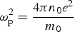 is the plasma frequency, ω is the laser frequency, γ = (1 + a02)1/2 is the relativistic Lorentz factor associated with the electron motion transverse to the laser propagation, and
 is the normalized vector potential. The interaction of ultra-intense laser radiation with plasma is important in number of applications such as fast-ignitor concept, X-ray lasers, ultra-high-gradient electron accelerators, and laser-induced lightning (Tajima & Dawson, Reference Tajima and Dawson1979; Umstadter et al., Reference Umstadter, Kim and Dodd1996; Tabak et al., Reference Tabak, Hammer, Glinsky, Kruer, Wilks, Woodworth, Campbell and Perry1994; Mackinnon et al., Reference Mackinnon, Borghesi, Gaillard, Malka, Willi, Offenberger, Pukhov and Meyer-Ter-Vehn1999; Sprangle et al., Reference Sprangle, Esarey, Ting and Joyce1988; Li et al., Reference Li, L'Huillier, Feray, Lompre and Mainfray1989; Kasparian et al., Reference Kasparian, Rodriguez, Mejean, Yu, Salmon, Wille, Bourayou, Frey, Andre, Mysyrowicz, Sauerbrey, Wolf and Woste2003; Pepin et al., Reference Pepin, Comtois, Vidal, Chien, Desparois, Johnston, Kieffer, Fontaine, Martin, Rizk, Potvin, Couture, Mercure, Bondiou-Clergerie and Lalande2001; Rodriguez et al., Reference Rodriguez, Sauerbrey, Wille, Wostle, Fujii, Andre, Mysyrowicz, Klingbeil, Rethmeier, Kalkner, Kasparian, Salmon, Yu and Wolf2002; Chen et al., Reference Chen, Unick, Vafaei-Najafabadi, Tusi, Fedosejevs, Naseri, Masson-Laborde and Rozmus2008; Neff et al., Reference Neff, Knobloch, Hoffmann, Tauschwitz and Yu2006; Yu et al., Reference Yu, Yu, Xu, Tian, Chen and Wong2007; Zhao et al., Reference Zhao, Yeh, Diels and Wang1993; Braun et al., Reference Braun, Korn, Liu, Du, Squier and Mourou1995; Yang et al., Reference Yang, Zhang, Yu, Li and Wei2001, Reference Yang, Zhang, Li, Chen, Teng, Wei and Sheng2002; Fontaine et al., Reference Fontaine, Vidal, Jiang, Chien, Comtois, Desparois, Johnston, Kieffer, Pepin and Mercure1999). Long-distance propagation of laser pulses in plasma is required for the successful implementation of the above mentioned applications. Self-guiding of intense laser pulses has been studied in many experiments (Krushelnick et al., Reference Krushelnick, Ting, Moore, Burris, Esaray, Sprangle and Baine1997; Sprangle et al., Reference Sprangle, Esarey, Ting and Joyce1988, Reference Sprangle, Esarey, Krall and Joyce1992). Self-guiding is expected due to self-focusing caused by the modification of the refractive plasma index resulting from the interaction with an intense laser. For effective guiding, balance between focusing and defocusing should be maintained over long distances. Self-guiding of laser pulses is limited by a number of effects such as energy depletion by diffraction, scattering, and beam splitting into filaments at high intensity. These difficulties can be avoided when the laser pulse to be guided does not create its own channel. Diffraction broadening of laser radiation limits the characteristic distance of propagation of laser radiation in vacuum up to one Rayleigh length,
 , where r 0 is the spot radius and λ is the laser wavelength. Therefore, guiding of the laser beam becomes essential for long-distance propagation in plasma. Several methods like capillary discharge, self-guiding, two-pulse technique, etc., have been proposed to extend the propagation distance of pulses beyond the diffraction limit (Rayleigh length), as reviewed by Esarey et al. (Reference Esarey, Sprangle, Krall and Ting1996, Reference Esarey, Sprangle, Krall and Ting1997).
In the present paper, two-pulse technique is used for guiding the laser pulse, in which the resultant plasma channel formed after the passage of the prepulse has plasma density minimum on axis as compared to the density at the edge of the plasma channel, and also have an axial variation of plasma density (Singh & Singh, Reference Singh and Singh2010).
In Singh and Singh (Reference Singh and Singh2010), the guided propagation was studied by taking the model proposed by Liu and Tripathi (Reference Liu and Tripathi1994), in which the relativistic effects are not included. Present work investigates the guiding of an intense laser beam under the effect of the relativistic nonlinearity, which comes into existence at higher powers. A laser beam with frequency ω, propagating in under-dense plasma (ωp < ω, where ωp is the plasma frequency), undergoes relativistic self-focusing as soon as its total power P exceeds the critical value 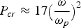 GW as established both theoretically (Max et al., Reference Max, Arons and Langdon1974; Hora, Reference Hora1975) and experimentally (Borisov et al., Reference Borisov, Borovskiy, Shiryaev, Korobkin, Prokhorov, Solem, Luk, Boyer and Rhodes1992; Monot et al., Reference Monot, Auguste, Gibbon, Jakober and Mainfray1995). In the present paper, the critical intensity of the laser beam, I cr, corresponding to the critical power, P cr, is 2 × 10¹⁸ W/cm2, whereas we take the intensity of the guided laser beam of the order of 1020 W/cm2 > I cr. This is required for the relativistic self-focusing and hence the relativistic nonlinearity is considered. In the present problem, we have taken short pulse lasers at relativistic intensities and ignored the time dependance, under quasi-static approximation, which assumes that in the time it takes the laser pulse to transit a plasma electron, the laser pulse does not significantly evolve. In other words, one can say that τL ≪ τE, where τL is the laser pulse duration, and τE is the laser pulse evolution time. Therefore, the plasma electrons experience a static laser field (independent of time). In Section 2, we develop the moment theory of self-defocusing of an ionizing prepulse. In Section 3, we investigate the guidance of the second pulse in the preformed plasma channel by taking into account the relativistic nonlinearity. Equations of the beam width parameters are solved numerically using the Runge-Kutta method. The results are discussed in Section 4.
2. SELF-DEFOCUSING OF PREPULSE
We consider the propagation of a Gaussian laser beam of frequency, ω, through a gas along the z-axis. The laser ionizes the gas via tunnel ionization in a time shorter than the pulse duration of the laser. Characteristics of plasma produced through the ionization of gas by the laser prepulse are calculated using the tunneling model of Keldysh (Reference Keldysh1965).
The rate at which the plasma density increases in tunnel ionization is given, for singly ionized gases, by Leemans et al. (Reference Leemans, Clayton, Mori, Marsh, Kaw, Dayson and Joshi1992)
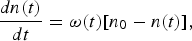
where n(t) is the time dependent electron plasma density, n 0 is the initial neutral gas density, and w(t) is given by Keldysh (Reference Keldysh1965)
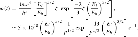
Here E i is the ionization potential of an atom, E h is the ionization potential of hydrogen,  , where
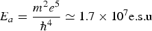 . is the atomic unit of the electric field, and |E| is the amplitude of the laser field, p is the laser power density in units of 1014 W/cm2, e and m are electronic charge, and mass, respectively, and
 , where h is the Plancks constant.
In the experiment performed by Durfee and Milchberg (Reference Durfee and Milchberg1993), a laser prepulse (10.6 µm, ~ 100 ps) forms a channel for the second delayed pulse. The laser intensity used was in the range 1013 – 1014 W/cm2. Sharp plasma density fallout was observed in Durfee and Milchberg's experiment, which was modeled by Liu and Tripathi (Reference Liu and Tripathi1994) as
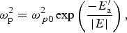
where 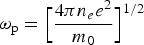 is the electron plasma frequency,
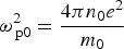 is a constant depending on the neutral particle density(n 0), and
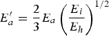 .
The electric vector E of the laser beam satisfies the wave equation

The electric vector E can be written as

The initial intensity distribution of the prepulse is assumed to be Gaussian and is given by

where A 00 is the maximum amplitude of electric field at r = 0 i.e., on the axis of the laser beam, r 2 = x 2 + y 2 and r 1 is the initial width of the laser beam at z = 0.
The transverse intensity distribution of the laser beam for z > 0 can be written as (Sodha et al., Reference Sodha, Ghatak, Tripathi and Wolf1976)
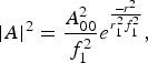
where r 1 represents the initial beam width at z = 0 and r 1f 1 represents the beam width of the prepulse for z > 0. Therefore, the function f 1 is termed as the dimensionless beam width parameter of the prepulse with f 1 = 1 at z = 0 [c.f. Eq. 23].
Following Eq. (3), the permittivity (ε) of the plasma may be written as

where

and ϕ (E.E *) is the nonlinear part of the dielectric constant given as

Now using Eq. (5) in the wave Eq. (4) and neglecting ∂2A/∂z 2 by using Wentzel-Kramers-Brillouin approximation, we get

Neglecting ∂2 A/∂z 2 implies that the solution of Eq. (11) can be obtained for a slowly converging and diverging beams.
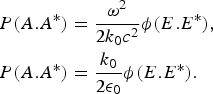
Now Eq. (11) can be rewritten as

where
According to the definition of second order moment, the mean square radius of the laser beam is given by

From above one can obtain the following equation

Eq. (15) is a second order differential equation, which governs the evolution of mean-square beam radius of the laser beam with the distance of propagation. First term on right-hand side of Eq. (15) contains two terms as evident from Eq. (17). First term on the right-hand side of Eq. (17) is a diffractive term, while the second term of Eq. (17) is a nonlinear refractive term. Second term of Eq. (15) is an intensity dependent refractive term as evident from Eq. (19), where I 0 and I 2 are the invariants of Eq. (12) (Lam et al., Reference Lam, Lippman and Tappert1977; Vlasov et al., Reference Vlasov, Petrischev and Talanov1971)
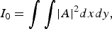

where from (Lam et al., Reference Lam, Lippman and Tappert1977, Vlasov et al., Reference Vlasov, Petrischev and Talanov1971)

and

From Eqs. (7), (14) and (16), it can be shown that


Now from Eqs. (15), (20), and (21), we get.

where ξ = (z/k 0r 12) is the dimensionless distance of propagation.
By using Eqs. (8), (10), (13), (17) – (19), and (22), we get following equation for the beam width parameter f 1

where

Initial conditions for numerically solving Eq. (23) is f 1 = 1,  at ξ = 0.
3. GUIDED PROPAGATION OF THE SECOND DELAYED PULSE
The plasma moves radially away from the axis after the passage of the prepulse. The density profile of the plasma channel formed by the prepulse is given by Liu and Tripathi (Reference Liu and Tripathi1994).

where α1 and α2 are monotonically decreasing functions of z;

The electric field vector of the second intense laser pulse can be expressed as

Due to the propagation of the ultra-intense laser pulse through the preformed plasma channel, nonlinear effects of relativistic mass variation becomes dominant and therefore, the non-relativistic plasma frequency, ωp in Eq. (24) in the preformed plasma channel after the passage of the prepulse, becomes relativistic plasma frequency, ωpr which is given as,  . Therefore, due to the relativistic plasma frequency ωpr, relativistically modified permittivity encountered by the guided ultra-intense laser pulse is given by
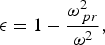
where m 0 is the rest mass of the electron, m is the relativistic mass of the electron, and  is the relativistic factor arising from the intensity dependence of the free-electron mass, where
 , ‘e’ is the electronic charge, ‘ω’ is the angular frequency of the incident laser beam, ‘c’ is the velocity of light, and E 0.E 0* is the Gaussian intensity distribution of the delayed pulse is given as
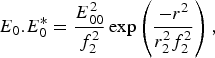
where r 2 represents beam width at z = 0 and r 2f 2 represents the beam width for z > 0. Therefore, f 2 is termed as dimensionless beam width parameter of the second delayed pulse with f 2 = 1 at z = 0. (c.f. Eq. (32)).
Following Eq. (24), permittivity can be expressed as

where
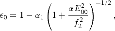
and
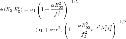
Now using Eqs. (25) and (28) in wave Eq. (4) and neglecting  by using Wentzel-Kramers-Brillouin approximation, we get

By following the same procedure as in Section 2 for the prepulse, we get the following equation for the beam width parameter f 2 of the second delayed pulse
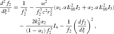
where
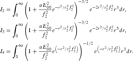
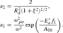
In Eq. (32), first term on the right-hand side is a diffractive term, and the next two terms are nonlinear refractive terms, while the last term is initially zero at ξ = 0. It evolves with propagation distance and counteracts diffraction. Focusing and Defocusing of the beam depends on the relative competition between these terms.
We have numerically solved Eq. (32) by taking initial conditions, 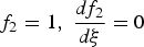 at ξ = 0 and for a model α2 (z) (Liu and Tripathi, Reference Liu and Tripathi1994)
4. DISCUSSION
The differential Eqs. (23) and (32) for the beam width parameter f 1 of the laser prepulse and f 2 of the guided laser pulse, respectively, have been solved numerically for the following set of parameters

and for different values of prepulse and guided beam intensities.
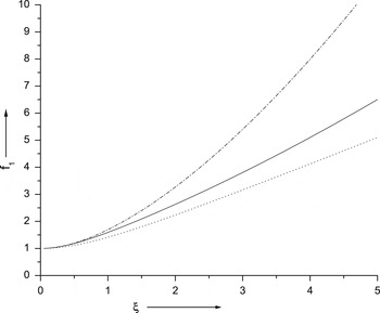
The results are depicted in the form of graphs in Figures 1 to 3. Eq. (23) is a second-order nonlinear ordinary differential equation, which governs the variation of the prepulse beam width parameter, f 1, with the dimensionless propagation distance, ξ. There are three terms on the right-hand side of Eq. (23). The first term is due to diffraction divergence and the second term is due to nonlinear refraction, which is responsible for the self-defocusing of the prepulse. Initially at ξ = 0, the third term is zero. It evolves with propagation distance and hence counteracts diffraction and self-defocusing of the prepulse.
Variation of beam width parameter, f 1 of prepulse with normalized propagation distance ξ.

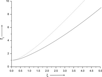
Variation of beam width parameter, f 1 of prepulse with normalized propagation distance,ξ, for two different values of prepulse intensites, 4.0 × 10¹⁷ W/cm2 for solid curve and 0.52 × 10¹⁷ W/cm2 for dotted curve.

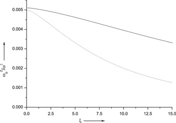
Variation of axial plasma density with normalized propagation distance, ξ for different values of prepulse intensites, 4.0 × 10¹⁷ W/cm2 for solid curve and 0.52 × 10¹⁷ W/cm2 for dotted curve.

Figure 1 depicts the variation of the prepulse beam width parameter, f 1, with the dimensionless propagation distance, ξ. The dotted curve corresponds to the case when only the diffraction divergence term is present and the other two terms are ignored. The semi-dotted curve corresponds to the case when only the first two terms, diffraction divergence and nonlinear refraction, are considered. The solid curve corresponds to the case when all three terms are taken into account. From Figure 1, it is observed that in all the cases the beam width parameter f 1 increases monotonically and leads to defocusing of the ionizing pulse.
It is clear from the semi-dotted curve that there is a sharp defocusing of the ionizing pulse when the first two terms are taken only. This is due to the fact that the first diffracting term is supplemented by the second refractive induced defocusing term.
When the prepulse propagates there is a finite contribution from the last term  , which prevents the prepulse from sharp defocusing as is evident from the solid curve of Figure 1. It hence makes a significant contribution in the formation of the plasma channel. The laser prepulse travels in a plasma having refractive index minimum at the axis and maximum at the edges. Therefore, it travels with larger phase velocity at the axis as compared to the phase velocity at the edges, it results into self defocusing of the prepulse. The beam width parameter and hence the laser spot size increases with propagation distance ξ. Due to the defocusing of the prepulse, the beam intensity decreases and, as a result, the ionization/density of the plasma decreases producing axially non-uniform plasma channel. The axial nonuniformity of the plasma channel off set the balance between divergence and convergence effects.
Figure 2 represents the variation of the beam width parameter, f 1, with the dimensionless propagation distance, ξ, for the two values of the prepulse intensities, 4.0 × 10¹⁷ W/cm2 and 0.52 × 10¹⁷ W/cm2. From figure 2, it is observed that with the increase in the intensity of the prepulse, the rate of defocusing decreases. Figure 3 represents the variation of the axial plasma density along the normalized propagation distance, ξ, for the two values of prepulse intensities, 4.0 × 10¹⁷ W/cm2 and 0.52 × 10¹⁷ W/cm2 as shown by solid curve and dotted curve, respectively. From Figure 3, it is observed that at intensity I = 0.52 × 10¹⁷ W/cm2, the variation of axial plasma density is more as compared to the variation of axial plasma density at intensity I = 4.0 × 10¹⁷ W/cm2 along the normalized distance of propagation, ξ. This is due to the fact that, at lower intensity defocusing is more as compared to the defocusing at higher intensity as evident from Figure 2. Thus, the axial nonuniformity of the plasma channel depends on the defocusing of the prepulse.
Eq. (32) is also a second-order nonlinear ordinary differential equation, which governs the variation of the guided pulse beam width parameter, f 2, with the dimensionless propagation distance, ξ. The first term on the right-hand side of Eq. (32) is due to diffraction divergence. The second term is due to nonlinear refraction, which counteracts the diffraction and is also responsible for the guidance of the laser pulse. There is a third term,  , initially at ξ = 0, this term is zero as
 . However, as the beam propagates, this term supports the second nonlinear refractive term and hence contributes significantly to the guidance of the laser pulse.
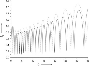
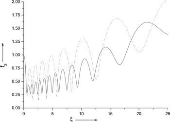
Figure 4 represents the variation of the guided pulse beam width parameter, f 2, with the dimensionless propagation distance, ξ, for two values of the guided pulse intensities, 5.0 × 10²⁰ W/cm2 and 7.5 × 10²⁰ W/cm2 at afixed value of the prepulse intensity of 4.0 × 10¹⁷ W/cm2. It is observed that for the guided pulse intensity of 5.0 × 10²⁰ W/cm2, f 2 varies in the range 0.0928 < f 2 < 1.414 as ξ goes from 0 to 24.0 as shown by the dotted curve. It is further observed that f 2 varies in the range 0.1224 < f 2 < 1.414 as ξ goes from 0 to 30.0 for the guided pulse intensity of 7.5 × 10²⁰ W/cm2 as shown by the solid curve. So, as we increase the intensity of the guided pulse from 5.0 × 10²⁰ W/cm2 to 7.5 × 10²⁰ W/cm2, laser guiding increases from 24.0 Rayleigh lengths to 30.0 Rayleigh lengths. This is due to the dominance of the nonlinear self focusing over the diffraction at higher intensity.
Variation of beam width parameter, f 2 of guided pulse with normalized distance of propagation, ξ, for two different values of the guided pulse intensities, 5.0 × 10²⁰ W/cm2 for dotted curve and 7.5 × 10²⁰ W/cm2 for solid curve at a fixed value of prepulse intensity 4.0 × 10¹⁷ W/cm2.

Figure 5 represents the variation of the guided pulse beam width parameter, f 2, with the dimensionless propagation distance, ξ, for two values of the guided pulse intensities, 5.0 × 10²⁰ W/cm2 and 7.5 × 10²⁰ W/cm2 at a fixed value of the prepulse intensity of 0.52 × 10¹⁷ W/cm2. It is observed that for the guided pulse intensity of 5.0 × 10²⁰ W/cm2, f 2 varies in the range 0.2986 < f 2 < 1.414 as ξ goes from 0 to 14.40 as shown by the dotted curve. It is further observed that f 2 varies in the range 0.2751 < f 2 < 1.414 as ξ goes from 0 to 19.30 for the guided pulse intensity of 7.5 × 10²⁰ W/cm2 as shown by the solid curve. So, as we increase the intensity of the guided pulse from 5.0 × 10²⁰ W/cm2 to 7.5 × 10²⁰ W/cm2, laser guiding increases from 14.40 Rayleigh lengths to 19.30 Rayleigh lengths. It is concluded from the above discussion that the propagation of guided laser pulse is highly dependent on the axial nonuniformity of the plasma channel. It is therefore observed that the propagation of the guided pulse is more in case of less axial nonuniform plasma channel.
Variation of beam width parameter, f 1 of guided pulse with normalized distance of propagation, ξ, for two different values of the guided pulse intensities, 5.0 × 10²⁰ W/cm2 for dotted curve and 7.5 × 10²⁰ W/cm2 for solid curve at a fixed value of prepulse intensity 0.52 × 10¹⁷ W/cm2.

In the present paper, the intensity of the guided laser beam is of the order of 1020 W/cm2, which is more than the critical intensity beyond which relativistic self-focusing sets in. Due to the high-intensity laser beam, the dielectric constant of the plasma takes the form  , where
 is the relativistic Lorentz factor. It is only important at very high intensities. In the low-intensity, non-relativistic regime, as considered in Singh and Singh (Reference Singh and Singh2010),
 holds true. As a result of this
 reduces to 1 and the relativistic dielectric constant
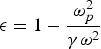 reduces to the non-relativistic dielectric constant
 , where
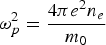 . So, under the above mentioned condition, the relativistic Eq. (32) derived for the beam width parameter of the second delayed pulse reduces exactly to the non-relativistic Eq. (39) of Singh and Singh, (Reference Singh and Singh2010). In the present case, laser guidance up to 30 Rayleigh lengths has been observed, whereas in the nonrelativistic case (Singh & Singh, Reference Singh and Singh2010), laser guiding over 42 Rayleigh lengths has been observed. This is due to the fact that, at very high intensities, the relativistic mass variation of the electrons as a result of the γ-factor, increases the index of refraction of the plasma in the centre of the beam, which further leads to tight self-focusing of the guided laser beam, which, due to diffraction, results in an interaction length shorter than that in the non-relativistic case.
A new route to the achievement of ignition in laser-induced fusion has been provided by the fast-ignitor concept in which an intense laser pulse is guided through a channel to the edge of the core where it is absorbed producing a large flux of Mev electrons (Tabak et al., Reference Tabak, Hammer, Glinsky, Kruer, Wilks, Woodworth, Campbell and Perry1994). These electrons then deposit their energy within the core, thus heating it to ignition temperature before hydrodynamic disassembly can take place. In this process, the intense channeling pulse must propagate through plasma regions without being absorbed and without beam break-up due to filamentation. So, it is very important for the fast-ignition scheme to understand if such propagation is possible.
In our present investigations, the guided laser pulse propagates through a plasma region created by the prepulse, without any absorption up to several Rayleigh lengths as is evident from Figures 4 and 5.
ACKNOWLEDGMENTS
The authors are thankful to the Ministry of Human Resources and Development of India for providing financial assistance for carrying out this work.