
I. INTRODUCTION
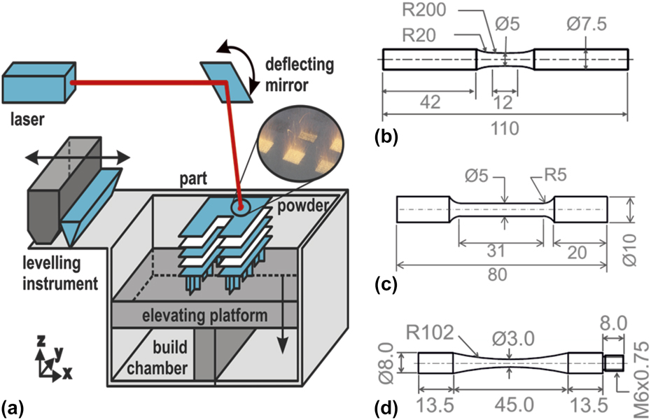
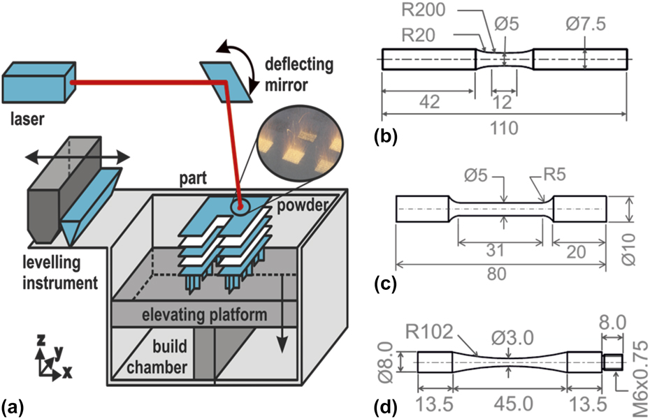
In selective laser melting (SLM), micro layers of powder material are consolidated by a laser fusion source, which scans the coated powder layers of the three-dimensional computer-aided design (3D-CAD) model in a chessboard like fashion. Controls of the laser source follow standard tessellation language file format to slice the 3D-CAD model and establish the contours of the current layer above which, a new layer is deposited. Reference Gibson, Rosen and Stucker1,Reference Gu, Meiners, Wissenbach and Poprawe2 The process schematic is portrayed in Fig. 1(a), which shows that after part slicing, a sequential process starts with the exposure of one powder layer to the laser energy, which fuses the selective layer locations. After selective melting of one layer, the build platform is lowered, equivalent to the thickness of one layer, and a new powder layer is spread by the coater and then exposed to the laser energy. So in this layer-wise fashion, a complete metallic component can be built and then removed from the build platform resulting in a part with near-net shape characteristics without extensive tooling requirements. With vast freeform fabrication capability, tailored medical implants were first of the various fields to tap the capabilities of the new technology. Reference van Bael, Chai, Truscello, Moesen, Kerckhofs, van Oosterwyck, Kruth and Schrooten3 This technology along with other emerging processes like electron beam melting (EBM) made low batch and job shop production economic again after the mass production revolution of subtractive and formative manufacturing processes. Reference Lewandowski and Seifi4,Reference Murr, Martinez, Amato, Gaytan, Hernandez, Ramirez, Shindo, Medina and Wicker5 With short lead times, less tooling requirements, and extensive functional tailoring capability, additive manufacturing processes seem to be on the way to transform mass production concepts into mass customization ones. Considering functional components, attempts have been made at producing tool inserts for machining processes by the deposition of cutting edges and surfaces on tool shanks, Reference Siddique, Wycisk, Tenkamp, Hoops, Behrens, Emmelmann, Walther, Borsutzki and Moninger6 the purpose of which is designing a hybrid manufacturing process in which only geometrically complex parts of a component are produced via additive manufacturing. From an operational point of view, the new robust SLM machines provide a very flexible tool, since the new platforms can be used as either stand-alone manufacturing platforms for direct manufacturing or as support platforms integrated with conventional manufacturing equipments.
(a) Schematic representation of the selective laser melting (SLM) process; specimen geometries for mechanical tests: (b) tensile and HCF tests for the AlSi12 alloy, (c) tensile tests for hybrid batches, and (d) VHCF tests.
Although SLM and EBM are part of the family of metal additive manufacturing processes, they have acquired significantly different characteristics. In contrast to SLM, powder layer thickness in EBM is usually around 100 µm; whereas, in SLM, this parameter has been reported to vary between 30 and 50 µm since electron beams have much more penetrating power than laser beams. Reference Murr, Gaytan, Ramirez, Martinez, Hernandez, Amato, Shindo, Medina and Wicker7,Reference Abele, Stoffregen, Kniepkamp, Lang and Hampe8 In EBM, the main fusion and consolidation scan of the powder material is preceded by preheating scans (up to ∼700 °C), and components are allowed to slowly cool down in the vacuum atmosphere inside the build chamber. Reference Guo, Ge and Lin9 This is a compulsory condition for the operation of electron beams, which is not necessary for the photon energy of laser beams. However, to constrain contamination and oxidation of powder during the fusion process, the atmosphere of the build chamber is saturated with an inert gas. Argon has been proven experimentally best-suited for achieving optimum densification characteristics. Reference Wang, Zhang, Fang and Sercombe10 These three main differences with respect to layer thickness, preheating of the powder, and postbuild cooling conditions did format the main difference in application fields of SLM and EBM processes. Since high temperatures are reachable in EBM, the process is considered best-suited for heat-resistant materials like intermetallics, e.g., titanium aluminides Ti–Al. Reference Hernandez, Li, Martinez, Murr, Pan, Amato, Cheng, Yang, Terrazas, Gaytan, Hao, Yang, Medina and Wicker11,Reference Schwerdtfeger and Körner12 This implies that light metals such as aluminum and magnesium would lie in the operational zone of SLM. Reference Louvis, Fox and Sutcliffe13,Reference Zhang, Liao and Coddet14 Titanium alloys, for example, have been processed successfully via SLM Reference Cain, Thijs, van Humbeeck, van Hooreweder and Knutsen15 and EBM Reference Al-Bermani, Blackmore, Zhang and Todd16 processes. The two processes induced different characteristic microstructures for the same composition. When processing Ti–6Al–4V, SLM resulted in a very fine quench-like microstructure, where acicular martensite α′ was the dominant feature of the microstructure. Reference Wycisk, Siddique, Herzog, Walther and Emmelmann17 In EBM-processed Ti–6Al–4V, the microstructure was mainly consisting of prior β grains with α on the grain boundaries. Reference Al-Bermani, Blackmore, Zhang and Todd16 In general, the microstructure can be judged as coarser in comparison to that obtained by the SLM processing of Ti–6Al–4V. As a result, SLM Ti–6Al–4V acquires a higher tensile strength than EBM Ti–6Al–4V at the expense of fracture strain, which is higher in EBM Ti–6Al–4V. Reference Rafi, Karthik, Gong, Starr and Stucker18
Application of SLM to aluminum alloys was not exploited as much as it was with titanium alloys because of the weldability issues since SLM is basically a micro scale fusion process of powder particles. In welding, aluminum alloys pose process challenges due to their physical and chemical properties. Aluminum is a light-weight, thermally conductive element, which in welding does not allow proper concentrations of energy at the point of application as heat is rapidly dissipated. Reference Norman, Hyde, Costello, Thompson, Birley and Prangnell19 The process difficulty is compounded by the high chemical affinity of aluminum to oxygen, which results in the formation of a hard and heat-resistant aluminum oxide Al2O3. This layer requires either a preprocess surface preparation or application of highly focused thermal energy to break through the oxide layer. Such conditions deemed fusion welding processes not optimum for aluminum alloys as compared to solid state welding processes like friction stir welding. Reference Threadgill, Leonard, Shercliff and Withers20,Reference Kaufmann, Imran, Wischeropp, Emmelmann, Siddique and Walther21 Only when high-performance SLM platforms became available, that the SLM processing of aluminum powder became possible, and the family of cast Al–Si alloys proved to be very successful in SLM processing. Reference Bremen, Meiners and Diatlov22 Alloys like AlSi12 and AlSi10Mg are reported to produce high relative density (>99%) parts. Reference Prashanth, Damodaram, Scudino, Wang, Prasad Rao and Eckert23–Reference Siddique, Wycisk, Frieling, Emmelmann and Walther25 The mechanical properties reported in either tensile or fatigue testing were comparable or superior to the respective cast alloys. Reference Siddique, Imran, Wycisk, Emmelmann and Walther26 This was attributed to the formation of very fine microstructures, which gives SLM aluminum alloys the extra strength at the expense of fracture strain. A relatively higher scatter in the fatigue properties was observed, which is attributed to the microporosity-induced stress concentration factors which promote crack initiation, sometimes simultaneously at various locations within the specimens. The stress raising effect was characterized as a function of size and location of the respective pore. Reference Siddique, Imran, Rauer, Kaloudis, Wycisk, Emmelmann and Walther27 Origins of porosity can be related to the high cooling rates the melt pool experiences during SLM depositions. This was not the case for EBM depositions for the reasons discussed above. So process adaptation attempts have been made aiming at a predeposition heating of the base plate, which should decrease cooling rates significantly. Application of the concept was carried out for AlSi10Mg at 300 °C Reference Brandl, Heckenberger, Holzinger and Buchbinder28 and for AlSi12 at 200 °C, Reference Siddique, Imran, Wycisk, Emmelmann and Walther26,Reference Siddique, Imran and Walther29,Reference Siddique, Imran, Wycisk, Emmelmann and Walther30 the result of which was a significant enhancement of the densification process and a subsequent reduction of remnant porosity. Consequently, scatter in fatigue strength was significantly reduced at the expense of the mean strength in the low cycle fatigue (LCF) regime. Otherwise, high cycle fatigue (HCF) and very high cycle fatigue (VHCF) strength in contrast to LCF experience a significant improvement as a result of application of base plate heating. Reference Siddique, Imran and Walther29 Such phenomenon highlights the potential for local property control and design of materials inside-out, given the freeform capabilities of metal additive manufacturing processes. Reference Siddique, Imran, Rauer, Kaloudis, Wycisk, Emmelmann and Walther27
With knowledge about properties of SLM aluminum alloys maturing, industrial applications are expected to gain momentum, especially in the industries where aluminum alloys are considered the main structural metals, i.e., aerospace and automotive industries. With strength superior to cast alloys, in addition to the freeform fabrication capability, SLM aluminum alloys are looking forward to be applied as structural elements in high-performance aircrafts and automobiles. In this process, characteristic qualifications of the new materials are reported to take place depending on a combination of destructive and nondestructive testing procedures.
The objective of this study centralizes around the aim of understanding the damage and fracture mechanisms, in HCF and VHCF range, of SLM structures as well as hybrid structures of aluminum alloys combining the SLM process with the conventional process to make use of the synergic effects of both the processes. This adds to the global aim of the SLM component’s qualification strategy. Hybrid SLM structures utilizing aluminum wrought alloys will be investigated to stand on the structural strength states as a result of hybrid manufacturing. Transformation of the mechanical properties as a result of the alteration of microstructure will be investigated by a stress relieving heat treatment study of the pure SLM and hybrid components. The study of microstructure and joint strength will serve as a database of mechanical properties resulting from tensile and fatigue tests to be used for design and subsequent manufacturing of functional components.
II. EXPERIMENTAL PROCEDURE
Specimens used for the investigations were manufactured in a selective laser melting machine system SLM 250 (SLM Solutions, Lübeck, Germany) fitted with a fiber laser with a capacity of 400 W having a build chamber of 250 × 250 × 280 mm3. The system has a modular construction and is integrated with the software AutoFabCAM (SLM Solutions, Lübeck, Germany) for data construction. To ensure minimum interaction with the atmospheric conditions, Argon gas was used as the inert medium. The volume energy density (E v) used was 39.6 J/mm3, which is a function of laser power (P), scan speed (v), hatch distance (d), and layer thickness (t), according to Eq. (1):
 $${E_{\rm{v}}} = {P \over {v \cdot d \cdot t}}\quad .$$
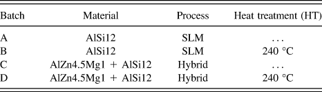
Al alloy AlSi12 was processed using a powder material with a diameter range of 20–63 µm. Specimens were manufactured vertical to the base platform such that the build direction corresponds to the axis of loading. For the investigations of hybrid structures, the AlZn4.5Mg1 alloy was used as the base material in the build chamber, and AlSi12 was laser melted on the top of the base material. Keeping in view the possibility of build-up of residual stresses in the SLM process due to high thermal gradients, half of the specimens were heat-treated at 240 °C for 2 h after SLM processing followed by oven cooling, the plan is listed in Table I.
Test plan for the manufacturing of SLM Al and hybrid Al structures.

After heat treatment, specimens were machined for mechanical tests as well as metallographic investigations. Preparation for metallographic investigations was performed as grinding steps until 0.5 µm grit and etched afterward with a combination of sodium hydroxide and nitric acid. Microstructural investigations as well as post mechanical testing fracture investigations were carried out in a scanning electron microscope Tescan Mira XMU (TESCAN, Brno, Czech Republic) by EOS.
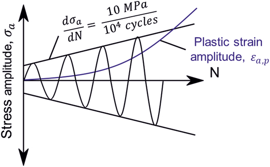
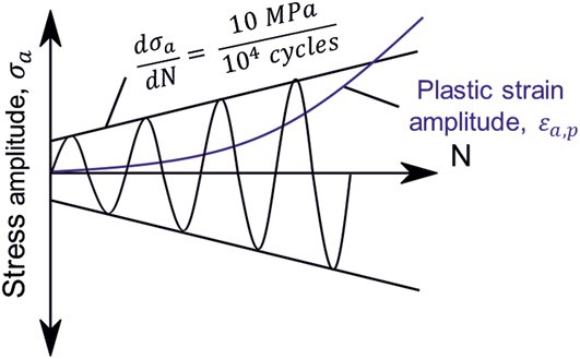
Tensile tests were carried out for batches A and B according to the geometry shown in Fig. 1(b), and for batches C and D according to the geometry shown in Fig. 1(c). Fatigue tests were conducted as a combination of multiple amplitude tests and constant amplitude tests. Multiple amplitude tests at continuously increasing stress amplitudes were carried out according to the illustration in Fig. 2. In this case, the starting load is applied at a level at which the material is expected to be virtually damage-free. The load was increased at a rate of 10 MPa per 104 cycles. The material reaction was measured in the form of plastic strain amplitude εa,p. The changes in response parameter give the rate of material response as a function of stress amplitude σa. Such a load procedure makes it possible to rapidly assess the relevant load range and is especially suitable in the process optimization phase oriented at fatigue strength. Further constant amplitude tests were also performed at the servohydraulic testing system Instron 8872 (Illinois Tool Works Inc., Glenview, Illinois) at a frequency of 20 Hz according to the specimen geometry in Fig. 1(b). VHCF tests were carried out at an ultrasonic fatigue testing system Shimadzu USF-2000 (Shimadzu Corp., Kyoto, Japan) at a frequency of 20 kHz according to the geometry shown in Fig. 1(d).
Illustration of continuously increasing multiple amplitude test.
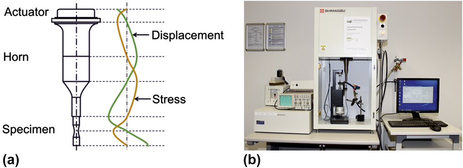
VHCF tests were carried out to investigate the fatigue strength until 109 cycles. To achieve such a high number of cycles at conventional fatigue testing systems, working at limited test frequency, is practically impossible. An ultrasonic fatigue testing system is based on generation of ultrasonic waves at 20 kHz. These waves are converted into mechanical vibrations through a piezoelectric actuator. The actuator is integrated to a resonance amplification system connected to the test specimen through a horn. Such a resonance system amplifies the mechanical vibrations in the actuator until it reaches the specimen which is threaded inside the horn. The specimen needs to be designed such that it can resonate at the system frequency of 20 kHz. The material properties of the specimen, i.e., density and elastic modulus, determine the inertia of the resonating module and, therefore, as the inertia changes for different materials, the corresponding specimen design has to be set to result in the resonance frequency. The resonance system has been designed such that the generated longitudinal waves have a maximum stress at the middle of the specimen and maximum displacement at the end of the specimen, which remains free in this case. Displacement at the free end of the specimen, measured through eddy current sensor, is used to calculate stresses in the specimen. The resonating principle of the ultrasonic fatigue (USF) testing system is illustrated in Fig. 3(a). Additionally, it is equipped with an air-cooling mechanism to control frequency-induced temperature variations in the specimen, which can be viewed in the test setup in Fig. 3(b). The test can be controlled in a way that the system will be resonating (pulse phase) for a specific time and will stop (pause phase) for another interval. For the current tests, the pulse:pause ratio was set to 50:50, to ensure that the loading-induced temperature increase during the test remains below 10 K, therefore resulting in an effective frequency of 10 kHz.
(a) Resonance mechanism in the USF testing system; (b) corresponding test setup.

III. RESULTS AND DISCUSSION
A. Microstructural characteristics
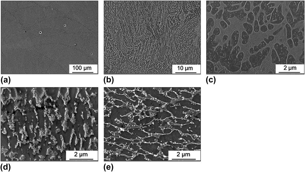
Figure 4 shows the microstructural features at different locations and magnifications. Figure 4(a) shows the purview, where a number of defects can be seen, such defects are either gas porosity or some unfused powder particles during the melting process. With the used parameters, the fraction of porosity was significantly reduced with a remnant porosity less than 0.4%. Additionally it shows the overview of the melt structure, where the overlapping tracks of the laser scans are visible. Relative detail is visible in Fig. 4(b), where the locations of the overlapping or double melting regions show a relatively coarse microstructure representative of the melt history. The intermediate regions between these double-melted regions are much finer owing to the prevalent thermal gradients in the SLM process. This morphology, when viewed at a higher magnification in Fig. 4(c), portrays an eutectic morphology consisting of a eutectic phase developed in the Al matrix. Precipitates can be noticed, at this magnification, which are distributed in the matrix. The small particle size as well as their distribution can be attributed to the higher cooling rate. Another feature in the microstructure is the spherodization capability as can be seen in Figs. 4(d)/4(e), which can increase the toughness of the material by increased elongation, while not affecting the strength values. Spherodized eutectic phase as well as Si particles, respectively, in Figs. 4(d)/4(e), are beneficial as compared to elongated or acicular formation and result in reduced stress concentrations.
Microstructural development of AlSi12 alloy in the SLM process: (a) purview with melt tracks and surface morphology, (b) microstructural features in single and double melting regions, (c) precipitate formation and eutectic, (d) spherodization of the eutectic phase in the double melting region, and (e) spherodization and precipitates in single melting region.

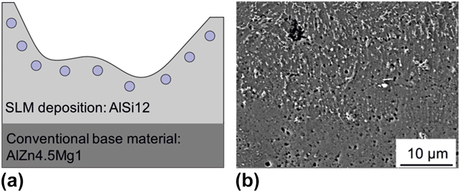
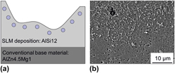
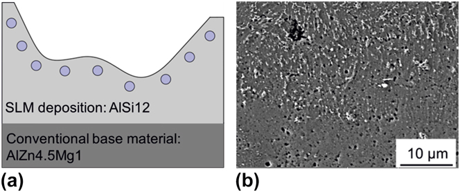
For the hybrid specimens, Fig. 5 shows the conceptual illustration where the AlSi12 alloy is melted on the conventional base material AlZn4.5Mg1 as shown in Fig. 5(a). The investigations on the specimens were carried out in a way that the interface remained at the middle of the longitudinal axis of tensile and fatigue specimens. The metallographic image in Fig. 5(b) shows the interface between conventional and SLM materials. Columnar dendrites are visible in the SLM-generated side, along with the existence of some joining imperfections between the two materials.
(a) Conceptualized hybrid structure and (b) morphology at the interface.
B. Quasistatic tensile properties
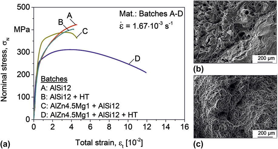
Quasistatic tensile test results for the four investigated configurations are plotted in Fig. 6(a). As-built AlSi12 specimens (batch A) have resulted in an ultimate tensile strength (UTS) of 420 MPa and a fracture strain of 4.5 × 10⁻²; after postprocess heat treatment, the tensile strength experiences a slight decrease with an accompanying decrease in strain. The strength of the SLM-processed alloy is higher than that of conventionally manufactured alloys, e.g., the AlSi12 cast alloy has a tensile strength of 150–170 MPa. Reference Schumacher31 Regarding the SLM processing of this alloy, the existing limited literature is available only from Prashanth et al. Reference Prashanth, Scudino, Klauss, Surreddi, Löber, Wang, Chaubey, Kühn and Eckert32 and Li et al. Reference Li, Wang, Saunders, Suvorova, Zhang, Liu, Fang, Huang and Sercombe33 Prashanth et al. processed the alloy with an energy density of 39.9 J/mm3 and got 380 MPa of tensile strength for the as-built specimens with strain of 3 × 10⁻². Li et al. have got a tensile strength of 360 MPa with a strain of 4 × 10⁻². Therefore, the current data confirms that the tensile strength of the SLM-processed alloy is 210–245% higher than that of conventionally manufactured alloy. This difference in the strength is attributed to the very fine microstructure (dendritic width of 0.3–0.6 µm) obtained by the SLM processing as compared to the grain size in the range of several hundred µm in casting processes. This microstructure size is, however, responsible for the decreased fracture strain—in the range of 4–5 × 10⁻² as compared to 5–6 × 10⁻² for cast alloys. For the hybrid specimens in the as-built condition (batch C), UTS of about 390 MPa is achieved with a corresponding fracture strain of 4.5 × 10⁻². As compared to the strain achieved in the pure conventionally manufactured alloy AlZn4.5Mg1 reaching to 14 × 10−2, this value of strain is much less. Reference Prashanth, Scudino, Klauss, Surreddi, Löber, Wang, Chaubey, Kühn and Eckert32 After postprocess heat treatment (batch D), it could be increased to 12 × 10−2, with a corresponding decrease in strength. In this case, the mutual interplay between the change in strength and strain is reciprocally related as it is for wrought alloys, in contrast to the SLM AlSi12 alloy. The reduced fracture strain in the as-built hybrid specimens is explained by the fractographic investigation of the tensile specimens in Fig. 6(b), where a brittle fracture is experienced in the presence of some joining defects. These joining defects can be a result of incomplete fusion of the two materials owing to the rapid processing speed, which will also cause development of residual stresses at the interface. The combined phenomena caused the fracture of the as-built specimens from the interface resulting in significantly reduced ductility. After the postprocess heat treatment, the fracture strain reached up to 12 × 10−2 with a decrease in tensile strength from 390 to 310 MPa. The reason behind this is the shift of the fracture mechanism from the joint to the conventional material AlZn4.5Mg1 which is more ductile as compared to the AlSi12 alloy. The corresponding fractograph in Fig. 6(c) explains the fracture mechanism which is representative of ductile fracture with deformation ridges, explaining that the post process heat treatment has made it possible for the fusion process at the interface to be completed, such that the fracture mechanism is shifted from the joint area to the core alloy. Mechanical properties of hybrid specimens could not be compared to any other reference, as no existing literature is available for the investigated alloys.
(a) Exemplary stress–strain curves for quasistatic tensile tests (HT: post-process heat treatment) and corresponding fractographs of tensile specimens: (b) as-built hybrid batch C, and (c) heat-treated hybrid batch D.

C. High and very high cycle fatigue properties
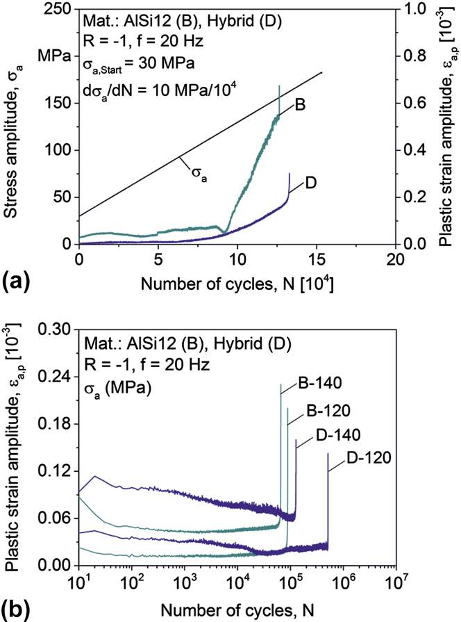
Fatigue tests were carried out only for the specimens after postprocess heat treatment to control the effect of process-induced residual stresses. To investigate the response of the alloys to cyclic loading, multiple amplitude fatigue tests were first carried out with an accompanied monitoring of plastic strain amplitude, represented in Fig. 7(a). General response to both the configurations is that the response parameter remains near-constant or increases at a very small rate until a specific stress amplitude is reached, after which the response parameter increases at a higher rate until the fracture of the specimen. The AlSi12 alloy (batch B) is fractured after 126,160 cycles; whereas the hybrid specimen (batch D) reached 132,790 cycles. The magnitude of the plastic strain amplitude in the hybrid specimen remained consistently lower than that of the AlSi12 specimen.
(a) Development of the plastic strain amplitude in multiple amplitude fatigue tests and (b) cyclic deformation curves for batches B and D at 120 and 140 MPa stress amplitudes.
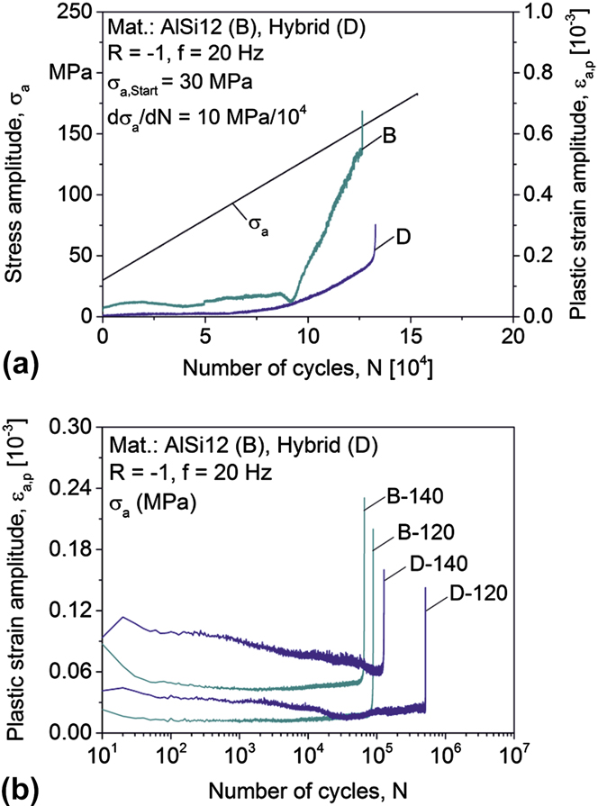
To further investigate the material behavior under fatigue loading, constant amplitude tests at 120 and 140 MPa were performed within the critical range of stress amplitude from multiple amplitude tests. The corresponding deformation curves are portrayed in Fig. 7(b). AlSi12 alloy (batch B) represents a stable cyclic response, after initial cycles of cyclic hardening, which remains constant until a slight softening is obtained before fracture. Hybrid specimens (batch D) experience cyclic hardening which continues for 140 MPa for a major proportion of the fatigue life. Cyclic hardening in hybrid specimens justifies the increased fatigue life as compared to SLM-processed AlSi12 alloy. Relatively stable cyclic responses in the pure SLM alloy (batch B) can be attributed to the less possibility of the dislocation movement due to obstacles obtained through the fine microstructure as well as formation of precipitates.
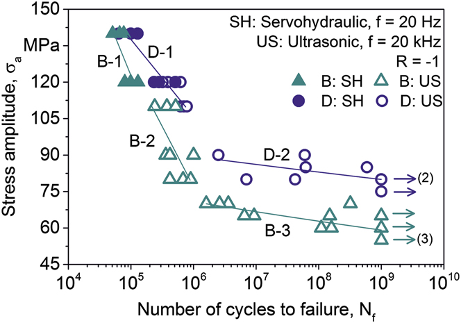
Stress-life (S-N) behavior until 109 cycles is presented in Fig. 8, which shows a consistently higher fatigue strength for hybrid specimens as compared to the pure AlSi12 alloy. Though fatigue fracture in hybrid specimens occured dominantly from SLM side of the specimen, the low accumulative plastic deformation in multiple amplitude tests in the hybrid specimens as well as hardening behavior in constant amplitude tests are attributed to the higher fatigue lives at all stresses.
Woehler curves for batches B and D until the VHCF regime.
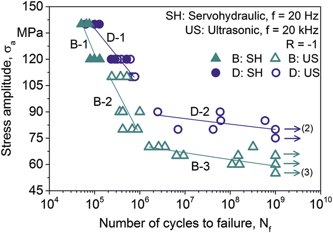
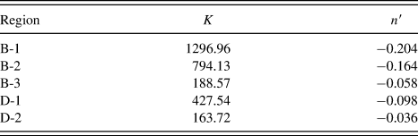
The mathematical representation of the relation between the stress amplitude σa and the fatigue life in cycles N f can be generalized by Eq. (2) and governed by the coefficient and exponent of the fatigue strength. These parameters were obtained for different sections of the Woehler curves and are listed in Table II.
 $${\sigma _{\rm{a}}} = K \cdot N_{\rm{f}}^{n'}\quad ,$$
where, σa is the stress amplitude, K is the fatigue strength coefficient, N f is the fatigue life in cycles, and n′ is the fatigue strength exponent.
Fitted values for fatigue strength coefficient and exponent in different regions for batches B and D.

With respect to the fitted parameters in Table II, batch-wise Woehler curves, in Fig. 8, can be classified into discrete domains. For batch B, three discrete regional domains can be mathematically represented according to Eq. (2). On the other hand, batch D developed only two distinctive regions. This means that batch B has two transition points one of which is between LCF and HCF and the other is between HCF and VHCF. Batch D has one transition point between HCF and VHCF. Such observations are in-line with the generalized Woehler curve until the ultra-HCF by Mughrabi, Reference Mughrabi34 where different fatigue regions can be dependent on the material or on material conditions.
The interpretation of this result can be that the fatigue strength of batch B has more stress level dependency than that of D. It also indicates the alteration of the fatigue damage mechanisms at the respective transition stress levels. For the region B-1, a higher value of the strength coefficient K is developed, which with respect to the fatigue strength reflects a higher rate of decay of life. The strength coefficient of region D-1 was lower. Thus, the rate of decay of strength, with respect to the fatigue life, was less, which shows the fatigue strength of the two batches approaching each other in the LCF region. Although, the strength coefficient K only represents the rate of decay along the domain, the discrete fatigue life is more influenced by the strength exponent n′. Until the HCF region, this was much lower for batch D than that of B. Thus, the higher fatigue life per stress amplitude of D than B is justified, from point of view of parameters of fatigue strength. In the VHCF region, the difference in fatigue parameters between the two batches becomes small which shows that the behavior is similar, but consistently higher fatigue strengths for the hybrid specimens. Fatigue strength at 109 cycles for the pure alloy turned out to be 60.5 MPa and that for the hybrid batch as 80.7 MPa. The VHCF data cannot be compared to existing data neither for the SLM-processed nor for conventionally manufactured alloy due to nonavailability of the literature in a VHCF region; however, comparison can be made in the HCF range. The conventionally manufactured alloy has a fatigue strength from 60 to 90 MPa at 5 × 10⁷ cycles. Reference Hesse35 For the current study, at this number of cycles, the fatigue strength ranges from 65 to 95 MPa, respectively, for the pure AlSi12 alloy and hybrid batch.
IV. CONCLUSIONS
The present study has investigated the processing chain of the AlSi12 alloy by the SLM process together with microstructure, quasistatic mechanical properties, HCF as well as very VHCF behavior, and the possibility of manufacturing hybrid structures. Almost fully dense parts were manufactured with remnant porosity less than 0.4%. Microstructure of the SLM-processed AlSi12 alloy resulted in a very fine dendritic structure, dendritic width range 0.3–0.6 µm, together with the formation of precipitates. The fine grain structure and morphology together with the precipitate formation resulted in increased quasistatic strength, UTS up to 420 MPa, as compared to that of the cast alloy. Spherodization of the eutectic phase has been observed which can be attributed to the result in elongation with the strain value slightly higher than 4 × 10⁻² even in the presence of fine grain sizes.
As-built hybrid specimens are fractured from the interface plane where SLM process started. The build-up of residual stresses as well as incomplete fusion due to relative difference in thermal properties of the two alloys is responsible for that. However, after post process heat treatment, these issues could be resolved and the fracture mechanism shifted from interface to the conventional alloy in quasistatic testing, and a higher strain 12 × 10−2 was achieved. In HCF and VHCF, the fatigue strength of the hybrid batch surpassed that of the pure SLM-processed AlSi12 alloy, the reason being the hardening effects in the combined zone of the two alloys, which encourages to employ the hybrid manufacturing processes to achieve synergic benefits of conventional and SLM processes.
ACKNOWLEDGMENTS
The authors would like to acknowledge Eric Wycisk and Claus Emmelmann from Institute of Laser and System Technologies (iLAS), Technical University Hamburg-Harburg (TUHH) regarding their excellent cooperation in manufacturing of investigated specimens.