1. ASSISTED GNSS
The late 20th century has seen the development of GPS and GLONASS – the two current fully deployed Global Navigation Satellite Systems (GNSS). In the 21st century, two additional GNSSs, the E.U.'s Galileo and China's Compass, will join the GNSS club. However, for the time being, GPS is the most popular and widely used GNSS. For the Standard Positioning Service, it may take more than 30 seconds for a GPS receiver to report a valid position (Bryant Reference Bryant2005). However, in difficult environments, such as urban canyons and indoors, weak satellite signals, multipath disturbances and blockages of satellites may extend this time significantly, and even make it impossible to acquire signals, decode data and generate a navigation solution. For many location-based services (LBS), and especially those requesting emergency assistance, the user cannot tolerate long waiting times or failed receiver operations. To overcome these problems, Assisted GPS (A-GPS), or more generally Assisted GNSS (A-GNSS), was developed.
When a GPS receiver starts up, it is in one of three states of readiness: Cold Start, Warm Start or Hot Start (u-blox AG 2006, Navman Reference Navman2007, Schuchman et al. Reference Schuchman, Bruno, Rennard and Moses1994)
• Cold Start: At receiver start up, the receiver has no information about the last computed position and the current time. This is the case when the real time clock (RTC) has not been running, or no valid ephemeris or almanac data is available. The ephemeris data is used in the precise satellite position calculation required for the position, velocity, time (PVT) solution. The almanac, on the other hand, is used to compute the approximate positions of the other satellites in the constellation (and whether they are above the receiver's horizon or not).
• Warm Start: In this state, the position and current time are known, the almanac is valid, but the ephemeris data validity has expired. It typically reflects the condition of continuous RTC operation with an accurate last known position available in memory. Most LBS applications will operate in this mode.
• Hot Start: In this state, all of the critical data (position, velocity, time, and satellite ephemeris) is valid and available in receiver memory. Hot start may reflect a software reset after a period of continuous navigation, or a return from a short idle period (i.e. a few minutes to a couple of hours) that was preceded by a period of continuous navigation.
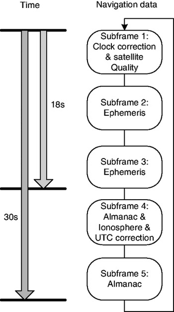
When the GPS receiver is in the Hot Start mode, it takes a very short period of time (only seconds) to generate a navigation solution in good visibility conditions. However, in Warm Start or Cold Start modes, it takes much longer. If the receiver has no prior information available (Cold Start), it must perform a search for satellite signals. The search unknowns are: visible satellites, the exact frequency of each satellite carrier due to Doppler and the PRN code offset between receiver and satellite (Parkinson, Spilker Reference Parkinson and Spilker1996). The receiver will first assume that a particular satellite is visible and will allocate a tracking channel for this satellite. A search across typically 30 or more Doppler bins is then made. For each Doppler bin, if using the time-domain signal acquisition approach, the receiver will need around 2 seconds to try to align the duplicate PRN code generated by the receiver with that transmitted by the satellite. After a satellite signal has been acquired, it can be tracked and the receiver decodes the navigation data: the time, the ephemeris, the almanac data, etc. (refer to Figure 1). It will take 18 to 30 seconds, and 12·5 minute to receive the ephemeris (3–5 sub-frames) and complete almanac (25 frames), respectively. If the environment is harsh, such as in obstructed urban areas or indoors, the receiver may “drop” or lose data bits, and hence it could take much longer to decode all the data bits. Once at least four satellites are being tracked, and their ephemeris is decoded, a receiver can perform the PVT calculations.
Navigation message data stream to be downloaded.

Obviously, if the Doppler shift, and all or parts of the navigation message information etc. can be obtained from other sources, time can be saved. The benefits of A-GPS include time-to-first-fix (TTFF) improvement, higher signal sensitivity and maximum availability (LaMance, Jarvinen & DeSalas Reference LaMance, Jarvinen and DeSalas2002, Moeglein, Krasner Reference Moeglein and Krasner2001).
2. A-GPS PROTOCOLS
Since the late 1990s, both GSM and CDMA cellular communities (now the 3GPP and 3GPP2 groups) have developed standards for control plane A-GPS messaging and defined performance metrics for the user equipment. The RRLP (Radio Resource Location Services (LCS) Protocol) is used by GSM (including GPRS, EGPRS) (3GPP 2009b). The RRC (Radio Resource Control) assistance data messages were designed for W-CDMA (3GPP 2009a), while CDMA (now CDMA2000) keeps updating its protocol (3GPP2 2009). The implementation of control plane (e.g., using some of the proprietary control bits in the base-mobile link) based A-GPS is complex and expensive because modifications to existing network equipment are required. An alternative user plane (an IP based architecture) solution has been developed by the Open Mobile Alliance (OMA) (http://www.openmobilealliance.org). The Secure User Plane Location (SUPL) needs only an IP-capable network (for example using GPRS) and requires minimum modification to the network, and hence can be deployed rapidly (Li et al. Reference Li, Mumford, Dempster and Rizos2010). The SUPL standard allows a device such as a mobile phone to connect to a location server using the TCP/IP protocol, and request its location (note: SUPL encapsulates the underlying RRLP). Many handset manufacturers produce A-GPS enabled mobile phones, including Apple, Nokia and HTC. Control plane approach used to dominate the A-GPS service, but more and more new handsets support user plane approach.
There are several GPS receiver manufacturers that claim they have an A-GPS enabled receiver. From their proprietary protocols (u-blox AG 2003, SiRF Technology 2005), the common messages used for A-GPS can be identified:
• GPS initial data, including time, position
• GPS Health, UTC and ionospheric model parameters
• Almanac data
• Ephemeris data
Time and position should be provided by a reliable source. For example the best initial estimate of a receiver's position is often coordinates of the base station which is currently communicating with the mobile phone. The last three messages are obtained from the GPS navigation message data.
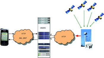
The Open Source GNSS Reference Server (OSGRS) provides an alternative to commercial A-GPS reference data solutions. It is very difficult for non-commercial organisations such as universities to utilise the current commercial A-GPS solutions for research purposes. An organisation may need to develop its own reference server and protocol. However, the development of the OSGRS allows anyone to develop a server with ease. The OSGRS is an Open Source Java application that provides data for A-GPS/GNSS clients. It is cross-platform and provides client applications with current, relevant and specific assistance data. The client may be an A-GPS/GNSS handset or an application that serves a network of A-GPS/GNSS handsets. OSGRS utilises the GNSS Reference Interface Protocol (GRIP). Figure 2 shows a client connecting to the OSGRS server to request assistance data, and the server generating the data and sending it to the client. OSGRS is also a user plane A-GPS implementation. GRIP defines the structure of the HTTP POST request as well as the structure of the XML document in the body of the request (Andrew Corporation 2007, Yan et al. Reference Yan, Mumford, Dempster, Rizos, Fernando and Hoang2007).
OSGRS application.

The significant difference between GRIP and other protocols is that its messages are in XML format. Requests and responses of most other protocols are in binary format. Using XML has at least two key advantages: it is easy to read and there are many libraries which can be used to parse XML data. XML Schema provides a means for defining the structure, content and semantics of XML documents. The XML Schema language is also referred to as the XML Schema Definition (XSD). XML Schema was approved by the World Wide Web Consortium (W3C) (http://www.w3.org/XML/Schema). The requests and responses in GRIP are defined by a set of XML Schema files. Currently, there are four files: GNSSRequest.xsd, GNSSResponse.xsd, GNSSErrorResponse.xsd and commonDataTypes.xsd. So far, only GPS is fully supported. But XML Schemas are extensible so GRIP can easily be extended to support other GNSS such as Galileo, GLONASS, and Compass. In the current version (v1.5) of GNSSRequest and GNSSResponse, the GNSSType is a required attribute. Each new version of the protocol will be accompanied by a set of XML Schemas.
The assistance data can be of the following types (defined by (Andrew Corporation 2007)):
• Reference time
• Navigation model (ephemeris)
• Ionosphere model
• UTC model
• Almanac
• Real-time integrity
• Differential corrections (DGNSS – RTCM Type 1)
• Acquisition Assistance
Compared with the common messages mentioned in the previous section, real-time integrity, differential corrections and acquisition assistance are new, but the position is missing. The real-time integrity information is a list of satellites that a receiver should not use as part of the PVT solution. They are satellites that the OSGRS has deemed to be functioning incorrectly. Acquisition assistance contains parameters for each visible satellite such as Doppler, code phase, elevation and azimuth. These parameters enable fast acquisition of the GPS/GNSS signals by the handset. The acquisition assistance messages can also be found in the control plane protocols. Differential corrections are reserved in case the handset can utilise differential GPS techniques to improve positioning accuracy. Differential GPS is a technique using a reference station or a reference station network to generate the corrections. Those corrections can help the user (a receiver called rover) to achieve higher accuracy. Only RTCM (Radio Technical Commission for Maritime) Type 1 (pseudo-range correction message) is used. In GRIP, the client is required to provide an approximate position first, and then the OSGRS server can calculate the assistance data based on that position. Hence the server assumes the client knows the handset's approximate position. How to obtain the handset's approximate position is a challenge. Other techniques such as WiFi positioning (Li et al. Reference Li, Wang, Lee, Dempster and Rizos2005, Furey, Curran & Mc Kevitt Reference Furey, Curran and Mc Kevitt2008) or mobile network positioning (Drane, Macnaughtan & Scott Reference Drane, Macnaughtan and Scott1998) may be utilized. Otherwise the base station or access point that the handset is connected to may have coordinates defined that can be used.
3. STATUS OF THE OSGRS
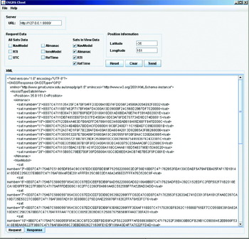
OSGRS is required to operate with reference GPS receiver(s). Presently NovAtel OEM2/3 or OEM4 receivers can be connected to the server to provide assistance data. A client simulator (PC-based client software, to be used in place of a commercial A-GPS enabled GPS receiver or mobile device. This software is also available open-source) can request different types of assistance data from the server and display the returned information on the screen. Figure 3 shows the GUI of the client software. At the top left of the GUI, the IP address of the server which hosts the OSGRS and the port (8080) is input. The client can request two sets of assistance data: the data of all satellites or the data of the satellites in view. The former set includes: reference time, navigation model, ionosphere model, UTC model, almanac and real-time integrity; the latter set consists of reference time, navigation model, almanac and real-time integrity. The user can choose the components of each set of assistance data. When the user requests the assistance data, an approximate latitude and longitude must be provided. After the request is sent, the XML file of the request would be shown in the edit box. By clicking the Response tab, the response from the server will be displayed. There are two modes of A-GPS, one is Mobile Station Based (MSB) A-GPS, and the other is Mobile Station Assisted (MSA) A-GPS (Harper et al. Reference Harper, Nicholson, Mumford and Poon2004). In MSB mode, the mobile station carries the calculation of PVT and reports to the server side if it is required. In MSA mode, the mobile station only receives a small amount of assistance data from the server and sends back the measurements to the server. The server carries out the calculation and reports it to the mobile station. OSGRS currently provides MSB service only.
The GUI of OSGRS “Client” software.

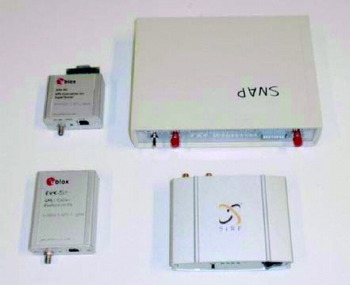
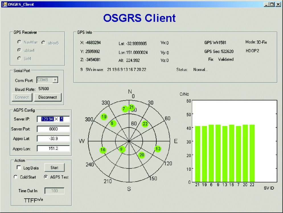
The simulator demonstrates how OSGRS works, however it cannot show a position solution unless an actual A-GPS receiver can obtain the assistance data from the OSGRS. To evaluate the OSGRS, client software has been developed. There are several GPS chipset manufacturers or developers in the marketplace that have A-GPS-enabled receivers. There are also a few PDAs or mobile phones that have the built-in A-GPS-enabled chipset. To use these PDAs or mobile phones to test OSGRS would be excellent; however, the interface and protocol of these chipsets are very difficult, if not impossible, to obtain. Hence using A-GPS-enabled receivers to test the OSGRS is the only choice at this stage. Four receivers, two from u-blox, LEA-4P and EVK-5H (www.u-blox.com), a Navman Jupiter 32 (SiRF chipset) (www.navmanwireless.com) and a Sirf GSCI-5000 (www.sirf.com) were chosen for the test. Figure 4 shows the test receivers. A C# application was developed as the client software to facilitate testing. The development environment was Visual Studio 2005. The OpenNETCF IO library and the receiver's USB drivers were utilized. A screenshot of the graphical user interface (GUI) is shown in Figure 5. The GUI shows the sky plot, the status of the satellites, and positioning results. For an A-GPS test, the coarse coordinates should be input first. The software can request and obtain assistance from the OSGRS through the internet, set the A-GPS receivers under test to cold start mode and log the receiver's output to a file. To connect to the internet, a WiFi or cellular network connection must be created.
The test A-GPS receivers (from left to right, top to bottom: u-blox LEA-4P, Navman Jupiter 32, u-blox EVK-5H and Sirf GSCI-5000).

The GUI of the OSGRS test software.

4. OSGRS TEST
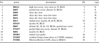
Thirteen test positions with known coordinates were selected around the UNSW campus. The test positions represent a broad range of environments including positions with an open sky view, positions with tree cover, adjacent to large buildings, under cover and indoors. Table 1 gives the details of all the test positions. The test positions can be classified into 5 categories: Indoor, Urban, Suburban, Rural and Open sky. The number of test positions of each category is 4, 3, 3, 2 and 1 respectively.
Details of all the test positions, DL=GPS difficulty level as estimated at the site (0 {least} to 10 {most} difficult) Note: this is estimated by the tester based primarily on how much open sky is visible; 0 means open sky (more than 90% sky), 10 means indoor (less than 10% sky). Type=Indoor, Urban, Suburban, Rural and Open sky.

4.1. Procedure
At each test position, 100 OSGRS location requests were initiated by the test software for each A-GPS receiver, data were logged within the terminal for post-processing. This provides 4 times (for 4 different receivers) 1300 location results for MSB. To average out the effect of the number of visible satellites and their geometric distribution, the 100 OSGRS location requests for each receiver at each test position were divided into four groups; each group consisting of 25 tests. The testing was carried out in the following way:
1. Set up the laptop and two A-GPS receivers at the test position 1
2. Initiate 25 OSGRS location requests (test two receivers at the same time)
3. Change to the other two receivers
4. Initiate 25 OSGRS location requests
5. Move to position 2, repeat step 2 to 4. Move to the next position until the group one tests are completed
6. Move back to test position 1 and carry out the next group test. Repeat until the four groups were completed.
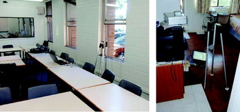
Figure 6 shows the typical setup of the A-GPS test. For comparison purposes, after the A-GPS test, the u-blox EVK-5H was used to carry out a standalone GPS test. The test positions were the same as those of the A-GPS test and the test procedure was also the same as for the A-GPS test. The testing period was about four weeks between March and April 2010.
The setup for the A-GPS test.

The procedure for each A-GPS test is initiated with a request from the test software (running on a laptop) to the OSGRS through a WiFi or mobile network. Soon afterwards, the laptop receives the assisted data and packs the data following the requirement of each type of receiver. Then the laptop initializes the receiver by sending a cold start command followed by the assisted data. While the GPS receiver is busy dealing with acquisition, tracking and calculation, the laptop listens to the receiver and logs all the related messages. The TTFF counts the time between when the cold start command is sent and when a valid 3D position is reported. The standalone GPS test is initiated by sending the cold start command from the test software and the rest is the same as that of the A-GPS test.
4.2. Results
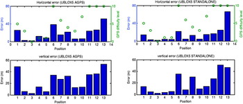
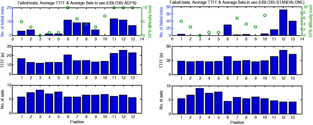
For comparison purposes, the A-GPS results and standalone results of the u-blox EVK-5H are shown together in Figures 7 to 10. Figure 7 gives the horizontal and vertical errors at each position. The errors vary significantly at different positions. For GPS operating in different environments, different positioning accuracies can be expected. No significant differences in accuracy can be found between the A-GPS and standalone tests (the performance of the standalone test looks even better; but the high failure rate of the standalone test should be considered. Refer to Figure 8). This is to be expected, as the raw pseudorange measurements used for the PVT solution will be similar. However, in Figure 8, significant differences of TTFF can be found. The average TTFF for each test position in the A-GPS test is almost half of that in the standalone test (Note: The cold start standalone GPS performance is very good. The new GPS receivers normally have a hard-coded almanac that can be used by the receiver even after a cold start has occurred. Hence the ‘cold’ start that was tested was not the traditional cold start). Shorter TTFF is the major advantage of A-GPS. There was not much difference between the two types of test in terms of the average number of satellites in use. Figure 8 also depicts the number of failed tests. Test failure is defined in following ways:
• Failed test type I: A test where the receiver failed to report the position within the predefined time interval (60 s)
• Failed test type II: A test where the provided position is grossly in error (the criterion is set as the horizontal distance error larger than 550 m)
In total, there are 72 (5·5%) and 167 (12·8%) failed tests out of 1,300 tests in A-GPS and standalone tests respectively. Type II failed tests dominate the failure in A-GPS tests (70 out of 72). On the contrary, in the standalone test, most of the failures are type I failed tests (164). The majority of failed tests can be found in the positions which have a high GPS difficulty level, especially indoors (position 6, 11, 12 and 13). The high failure rate of the standalone test indicates that in poor conditions, A-GPS works where standalone GPS does not, which validates its use.
The horizontal errors (upper plots) and vertical errors of u-blox EVK-5H A-GPS (left) and standalone (right) tests. The upper plots also shows the GPS difficulty level.

The number of failed tests, the average TTFF and the average number of satellites in use for each test position in u-blox EVK-5H A-GPS (left) and standalone (right) tests.

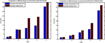
Average horizontal and vertical errors as a function of environmental type. Types 1 to 5 are Open sky, Rural, Suburban, Urban, and Indoor (left, A-GPS; right standalone GPS).

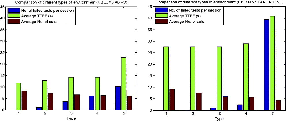
Number of failed tests per session, average TTFF, and average number of satellites in use as a function of environment type (left, A-GPS; right standalone GPS.

The effects of the environment are of interest. Data were analyzed based on the five different environment types defined in Table 1. Figures 9 and 10 show the results for the five types of environment. There is a clear trend that the positioning error (including horizontal and vertical errors) increases when the difficulty level goes up. It is well know that DOP (dilution of position) is a mathematical representation for the quality of the GPS position solution. The main factors affecting DOP are the number of satellites being tracked and where these satellites are positioned in the sky. Horizontal DOP is normally better than vertical DOP because no satellites below the horizon are visible. As expected, the vertical errors are larger than the horizontal errors. There is also a trend of a decreasing number of satellites in use and increasing TTFF with respect to the increasing difficulty, although not significant. Furthermore, the rates of failed test are positively related to the difficulty level.
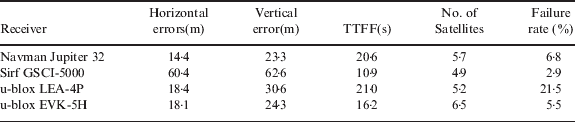
To compare the performance of the four types of A-GPS enabled GPS receivers, Table 2 summarizes the key results of A-GPS tests. The average TTFFs of A-GPS test for all four different types of receivers are significantly shorter than that of standalone GPS test (36·1 s), the failure rates of A-GPS tests are lower than that of standalone GPS test (except u-blox LEA-4P). The TTFF of Sirf GSCI-5000 is the shortest and the failure rate of this receiver is the lowest; nevertheless, the positioning error and number of satellites are the worst. Normally, more satellites mean better DOP. It appears that to achieve a short TTFF and low failure rate, the minimal number of required satellites are used to generate the positioning result as early as possible (no redundancy, bad DOP). Hence the accuracy is sacrificed. Generally, the performance of u-blox EVK-5H, which is the newest receiver, is the best.
Comparison of A-GPS performance of different receivers using OSGRS.
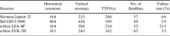
The tests show that OSGRS works well; it can provide the assisted data to decrease the TTFF and the failure rate in harsh environments significantly, but the positioning accuracy is not necessarily improved.
5. FUTURE WORK
In future versions of GRIP, more GNSSs will be included: Galileo, GLONASS and Compass. GLONASS will be the priority as it is the only other GNSS system that is almost fully deployed (currently about 20 satellites available) and achieves global coverage. However, the system's frequency division multiple access (FDMA) design requires a different front-end for the A-GNSS receivers. The good news is the next-generation GLONASS-K will begin launching next year and will include a code division multiple access (CDMA) signal on L3 (Gibbons Reference Gibbons2009).
The international GNSS service (IGS) global tracking network of more than 300 permanent, continuously-operating GNSS stations provides a rich data set to generate precise products such as satellite ephemerides and clock solutions. Utilisation of the IGS products to generate GNSS assistance/augmentation messages is of great interest. The advantages are obvious: global coverage, high precision, products free of charge. The real-time pilot project within the IGS will generate data streams that can be converted to the GRIP protocol.
So far, PDAs with built-in GPS chipset cannot support GRIP. The development of a real client is necessary. The performance of OSGRS still has room for improvement. Li et al. (Li et al. Reference Li, Mumford, Dempster and Rizos2010) reported 11·7 s TTFF, very low failure rate (0·9%) in a SUPL test. SUPL is much more complex than GRIP. The Mio A701 which has a built-in Sirf chipset was chosen for the SUPL survey as a generic SUPL-enabled terminal. The testing software was developed by Sirf. The performance of SUPL may be optimized. To improve the performance of OSGRS, further investigation is needed.