Introduction: The 5 nm, 500°C, 20 m/s, 1.5 billion per year challenge
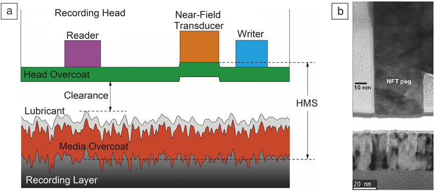
Throughout the 60-year history of the hard-disk drive, there has always been a host of technical obstacles impeding the next improvement in data-storage performance, including many at the head–disk interface. The challenges that the industry has overcome have ranged from mechanical (media vibration, spindle motor dynamics, evolutionary air bearing design) to tribological (media roughness, contact start-stop tribology, tribochemical reactions, lubricant chemistry, new forms of diamond-like carbon coatings), to dimensional (spacing reductions, reducing head topographical features, sub-2-nm-thick coatings).Reference Bhushan1–Reference Tsai and Bogy3 The resulting contemporary hard-disk drive integrates a host of nanoscale materials, device technologies, and manufacturing processes to enable Gb/s recording using a head–medium clearance of less than 2 nm. This clearance represents the physical separation between the recording medium and the recording head (Figure 1).
(a) Schematic representation of the head–disk interface and key contributors to the head–medium spacing (HMS) budget.Reference Kiely, Jones, Wang, Yang, Scholz, Benakli, Brand and Ganagopadhyay4 (b) Composite image of individual transmission electron microscope images depicting the near-field transducer (NFT) peg, the media, and the spacing between them.

This extremely small clearance is key in the head–medium spacing (HMS), which reflects the net separation between either the writer or reader element in the recording head and the recording medium. Because the read and write performances are sensitive to this separation, HMS is a key determinant of the performance of a hard-disk drive.Reference Kiely, Jones, Wang, Yang, Scholz, Benakli, Brand and Ganagopadhyay4 For a recording density of 2–3 Tbpsi, the HMS target is approximately 5 nm.Reference Marchon, Pitchford, Hsia and Gangopadhyay5 Attaining that HMS in a reliable device is one of the primary goals for head–disk interface development.
While attaining such small spacing in a carefully controlled test configuration is not a trivial challenge, it is a tremendous challenge to do so while maintaining that spacing at a speed of 20 m/s (to enable rapid data transfer) and to do it reliably for 1.5 billion heads per year without the cost or complexity of additional electronics or metrology systems.
Attaining this level of precision on a mass-production scale is accomplished by combining passive and active actuation methods. The vehicle to create the passive (or coarse) spacing is a true wonder of engineering: the pivoted, self-actuating fluid slider bearing,Reference Gross6 or simply, the “air bearing.” After the head read and write transducers are created via thin-film microfabrication techniques, the wafer is diced and the air bearing is formed in the disk-facing surface using ion-beam etch processes. In this way, the transducers (magnetic and plasmonic) are embedded in a surface that also serves as a mechanical bearing surface. This surface has many of the same requirements that large-scale tribological bearing surfaces have, such as hardness and smoothness, but with requirements that are scaled down to the nanoscale. Current air bearings are designed to create a head–media clearance of 5–10 nm, and the surfaces of the head and media need to have subnanometer roughness characteristics, making them some of the smoothest mass-produced surfaces.
The final piece of spacing control is performed by a thin-film device fabricated near the read-write transducers that relies on thermal expansion to actively actuate (extend or retract) the read-write and plasmonic transducers. This thermal fly-height control device or “heater” creates a small amount of expansion (∼5–10 nm) with a fast response time, and when combined with the readback sensitivity of the reader element, provides a closed-loop control system with precision in the sub-Ångstrom level.
The addition of heat-assisted magnetic recording (HAMR) demands these same requirements be met, but at significantly higher temperatures. HAMR brings the challenge of maintaining reliability at temperatures high enough to reach the Curie temperature of the recording layer, which is approximately 480°C.Reference Kryder, Gage, McDaniel, Challener, Rottmayer, Ju, Hsia and Erden7 These temperatures will challenge the thermal stability of the materials that enable current conventional (perpendicular) magnetic recording. Since both the recording head and media rely on forms of diamond-like carbon as tribological coatings, both head and media are at risk.Reference Grill8 Thermal decomposition of protective coatings is potentially a greater risk on the head, since it remains at a high temperature throughout the writing process, whereas any media surface is heated only when data is written to that particular location. For the media, an additional potential failure mode is desorption of the media lubricant, which is a thin layer of perfluorinated polyether fluid that improves tribological performance.Reference Tsai and Bogy3 Elevated temperatures may induce unwanted chemical reactions of interface contaminants, such that maintaining an interface that is clean enough to maintain the required head-media spacing is a challenge.
Media overcoat
In order to protect the magnetic recording surface from mechanical interactions and chemical degradation, recording media surfaces are coated with a tribological coating. Historically, various embodiments of diamond-like carbon have been the most successful media overcoats.Reference Tsai and Bogy3,Reference Grill8 Because there is a limit to the thermal stability of carbon films, heating during the HAMR write process presents a challenge to media surface engineering.Reference Mate9–Reference Joshi, Nimmagadda and Herrington12 Individual bits on the HAMR disk undergo rapid heating to a peak temperature that is higher than the Curie temperature (T C) of the medium. The duration of the heating process is between 5 ns and 200 ns, giving a heating rate of >1010 K/s, depending on operating conditions.Reference Challener, Erden, Gage, Hsia, Ju, Kryder, McDaniel and Rottmayer13 With repetitive heating, the carbon film could be transformed and lose functional performance. The extent of this change establishes the practical limit for the use of any specific carbon film in the HAMR head–disk interface.
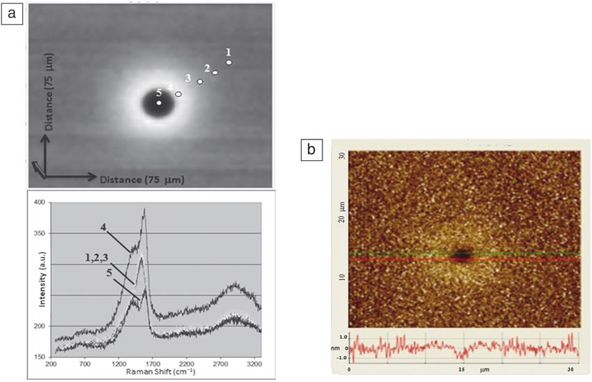
Among the techniques used for understanding the thermal stability limits of carbon films, the pump-probe technique is particularly effective because it efficiently probes the energetic and kinetics of degradation processes and can be applied to production recording media. The technique uses two lasers that are coincidently focused on the surface being studied: one to heat the surface and a second to probe the resulting physical and chemical changes. As an example, Figure 2 illustrates surface analysis after pump-probe measurements, which caused the medium surface to reach 480°C for 0.5 s. Changes in the film were measured by “nano-Raman” spectroscopy and atomic force microscopy (AFM). Results from the two techniques show (Figure 2) that the carbon bonding has changed to contain an increased number of sp 2 sites after heating, and there is carbon loss at the center of the irradiated spot where the media temperature is highest. Thus, at a medium temperature of approximately 450°C, the carbon film is transformed to a phase containing significantly more sp 2 carbon sites arranged in a ring-like structure. Such sites are more easily oxidized, leading to the eventual thinning of the carbon. The activation energy for carbon loss, determined via Arrhenius analysis of several tests, was 0.6 eV, which is at the lower range of reported activation energies that are obtained with much slower heating rates and much longer dwell times.Reference Wang, Komvopoulos, Rose and Marchon11,Reference Chowalla, Ferrari, Robertson and Amaratunga14,Reference Louro, Wagner Moura, Carvalho, Stueber and Cavaleiro15 Using these measurements, the rate of material thermal degradation can be estimated and extrapolated to expected HAMR product lifetimes. AFM studies indicate that the films lost approximately 0.5 nm–1 nm per second of irradiation. If during the 5–10-year lifetime of a hard-disk drive in the field, any one media surface location is expected to be written 106 times, then assuming a heating duration of 10–8 s, the cumulative film loss is expected to be 0.01 nm. This level of film loss is smaller than the positional variation in deposited film thickness, and would have negligible impact on product reliability.
Analysis of media samples after irradiation with a free-space laser beam.Reference Jones, Ahner, Platt, Tang and Hohlfield10 (a) Raman measurements of the carbon surface showing the mapped integrated intensity in the D and G-band (upper panel), where darker indicates less intensity. The lower panel shows specific spectra taken at the numbered positions indicated on the upper panel. (b) Atomic force microscope height map of the region irradiated at 480°C for 0.5 s, showing the carbon loss in the center of the irradiated region and some swelling surrounding the thinned region.

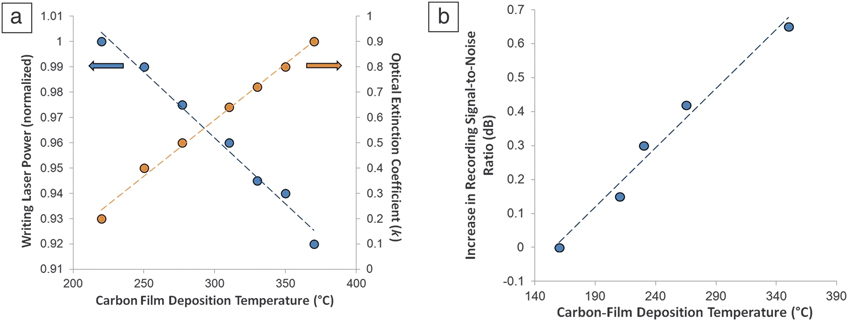
HAMR brings an additional requirement to the media overcoat—that it be an effective component in the plasmonic recording process. The carbon film is in the gap between the plasmonic transducer and the medium, and its impact on the recording process can be significant. The optical properties of the films are process dependent, and the optical gap, controlled by the sp Reference Jorgensen2 cluster size, can be optimized for HAMR recording. An example of this is shown in Figure 3, where the optical extinction coefficient varies with overcoat deposition temperature, ranging from 0.2 at 220°C to 0.9 at 360°C.
The impact of carbon deposition temperature on recording performance.Reference Jones, Fan, Ma, Wang and Tang40 (a) The optical extinction coefficient k (measured at 800-nm wavelength) of carbon films deposited at various temperatures and the normalized laser power needed to attain heat-assisted magnetic recording (HAMR) writing at a target track width. The laser power is normalized to that for a carbon layer deposited at 220°C. (b) Measured recording signal-to-noise ratio increase of HAMR media having a carbon layer deposited with increasing temperature. Data were taken at fixed track width relative to 160°C conditions and offset to place the 160°C result at 0 dB.

With higher optical extinction coefficients, there is a greater loss of the |E|2 field (laser light) within the carbon, more efficient heating of the media, and a reduction in required laser power. For these films, the increase in optical extinction coefficient reduced the laser power required by 8% (Figure 3). Additionally, due to the local nature of the additional heating of the carbon film, the thermal gradient in the recording media can be improved. The improvement in recorded signal-to-noise ratio (SNR) is shown in Figure 3 and illustrates a 0.65 dB increase in SNR for those films that have higher optical extinction coefficients. These indicate that optimization is required to balance recording SNR, thermal robustness, and mechanical integrity in the HAMR media overcoat.
Lubricant
For the past several decades, and since the beginning of optical or plasmonic heat-assisted recording, thermal stability of the media lubricant has been highlighted as a serious reliability concern.Reference Kryder, Gage, McDaniel, Challener, Rottmayer, Ju, Hsia and Erden7,Reference Hsia, Jones, Li and Hohlfeld16 Typical hard-disk drive lubricants are high-molecular-weight perfluorinated polymers, selected due to their lubricity, good flow characteristics, chemical stability, and low vapor pressure.Reference Bhushan1,Reference Johnson, Mate, Merz, White and Wu17 Even at a thickness of 1–2 nm, for a reliable recording surface, lubricant molecules must diffuse to regions of the disk surface that have had lubricant removed or thinned through mechanical or thermal means.Reference Bhushan1
Because of the fluid nature of the lubricant, there has been a longstanding concern with thermally driven lubricant flow.Reference Wu18–Reference Tagawa and Tani24 Thermocapillary shear stress is one of the mechanisms causing lubricant displacement during HAMR writing; it arises from the temperature-dependent nature of surface tension. This thermally driven shear stress depends on the local thermal gradient (dT/dx) and acts to move the lubricant fluid from the hotter regions to cooler ones, thereby deforming the local lubricant profile by “piling up” lubricant in the cooler outer edges of the thermal spot.Reference Zheng, Zhou and Huang20 Another thermal risk, evaporation, is the second dominating effect that deforms the lubricant film by removing lubricant from the disk surface.Reference Ma, Chen and Liu25,Reference Tagawa, Kakitani, Tani, Iketani and Nakano26
These two thermally driven mechanisms can change the lubricant thickness locally and cause the reliability to be sensitive to the thermal spot size. For spot sizes of ∼50 nm diameter and smaller, the thermocapillary stress dominates; when the spot size approaches 1 μm or larger, evaporation dominates.Reference Dahl and Bogy21 The competition between decomposition and evaporation rates is largely determined by the heating rate and molecular weight of the lubricant.Reference Lim and Gellman27 At the high heating rate used in HAMR, approximately 1011 K/s, and for typical hard-disk drive lubricants (e.g., Ztetraol, 2700 g/mole), this competition becomes dominated by evaporation, and decomposition should not significantly contribute. Studies of lubricant thermocapillary flow and evaporation demonstrate the agreement between predicted lubricant flow based on modeling and measurements.
Head overcoat
Conventional recording-head overcoats comprise two layers, an adhesion layer (e.g., amorphous silicon) and a layer of diamond-like carbon. The adhesion layer is needed to promote carbon adhesion to the various metals and oxides present at the surface of the recording head, and it also contributes to environmental (corrosion) protection. Filtered cathodic arc carbon has been used as the preferred material because of its combination of excellent wear resistance, good environmental protection, and the capability to deposit films thinner than several nanometers in a mass-production environment.
In HAMR, the high local temperature at the near-field transducer creates several challenges for the head overcoat. Thermal gradients in the head induce strain gradients that challenge the mechanical integrity of the film. Surface defects and recording head materials with mismatched elastic moduli contribute to these locally high strains. Because the recording head becomes heated when writing each bit, the head overcoat must withstand many terabits of recording (or tera-cycles of heating), leading to the potential for cyclic damage accumulation, analogous to fatigue. Foremost, though, is the thermal stability of carbon at high temperatures.
Carbon thermal stability
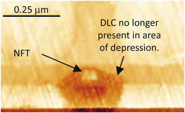
At higher temperatures, carbon films are susceptible to structural changes, as the sp 3:sp Reference Jorgensen2 ratio changes toward the more graphitic sp Reference Jorgensen2 configuration.Reference Ferrari, Kleinsorge, Morrison, Hart, Stolojan and Robertson28 This change is associated with a degradation of desired film properties (e.g., hardness, wear resistance). There have been studies showing that carbon films deposited using a filtered cathodic arc method maintain compositional stability at temperatures as high as 850°C.Reference Ferrari, Kleinsorge, Morrison, Hart, Stolojan and Robertson28 However, for thinner films and higher thermal gradients, the threshold for thermally induced structural changes is lower.Reference Wang and Komvopoulos29 For HAMR recording, the operational temperatures may be greater than 300°C near the NFT, which can be sufficient to graphitize and oxidize the film.Reference Wang, Komvopoulos, Rose and Marchon11,Reference Marchon, Guo, Pathem, Rose, Dai, Feliss, Schreck, Reiner, Mosendz, Takano, Do, Burns and Saito30 When this happens, the carbon combusts, leaving only the adhesion layer, as illustrated in Figure 4.
Atomic force microscope image of the write transducer area on the air-bearing surface following repeated write cycles. The circular darker region represents the area where carbon has decomposed and evaporated. Note: NFT, near-field transducer; DLC, diamond-like carbon.

Among the strategies for improving the thermal robustness of head overcoats, the addition of species that form more thermally stable sp 3 bonds is one showing some promise. Adding Si or SiOx to carbon has shown benefit, especially at higher thicknesses.Reference Peng, Sergiienko, Mangolini, Stallworth, Greenbaum and Carpick31 Molecular dynamics simulations show that incorporating SiOx promotes sp 3 bonding in the deposited film and also reduces the number of strained C–C bonds, which are likely the first bonds to rehybridize when heated. In a similar vein, the addition of boron to carbon films also increases the sp 3:sp 2 carbon ratio.Reference Ahmad and Alsaad32 As films are thinned, doping becomes less attractive, so alternative, noncarbon-based materials are also in development, although most suffer from having to sacrifice tribological performance for thermal and oxidative stability.
Additionally, new coating materials should also not significantly impact surface plasmon energy transfer. Similar to the media overcoat, because plasmonic energy transmission occurs through the head overcoat, it becomes part of the recording system, but unlike the media, it is undesirable to absorb energy in the head. Therefore, a low optical extinction coefficient is desirable. Materials with higher optical extinction coefficients lead to optical losses, higher temperatures, and less efficient recording. This imposes an additional consideration when optimizing materials that satisfy thermal, oxidative, and tribological performance of the head overcoat. Patterned overcoats, in which coating materials and thicknesses are tailored for different functional regions of the recording head, may provide the best opportunity to optimize head coatings for various performance requirements.Reference Rejda, Stephan, Nguyen, Zuckerman, Kunkel, Cole, Seigler and Rea33,Reference Khamnualthong, Siangchaew and Phongwanitchaya34
Write-induced head contamination
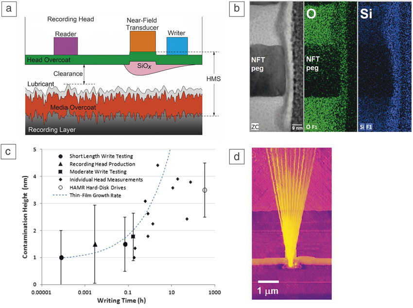
In addition to the materials engineered into the head and media, materials that the interface encounters during operation are an additional concern for the HAMR head–disk interface. With relative head-disk speeds of 10–20 m/s, the recording head can be expected to encounter 1 × 10⁸ meters of the media surface, albeit most of it as repeat encounter. With head–media spaces targets of only 5 nm, trace amounts of contamination can impact the interface. The risk of contamination impacting optical recording has been known for some time, even in near-field optical recording.Reference Novotny and Hajjar35 More recently, the impact of write-induced contamination in HAMR has been identified and several mechanisms hypothesized.Reference Kiely, Jones, Yang, Brand, Anaya-Dufresne, Fletcher, Zavaliche, Toivola, Duda and Johnson36–Reference Yang, Li, Stirniman, Yan, Zavaliche, Wang, Huang, Tang, Jones, Kiely and Brand38 Contamination in HAMR originates at the NFT on the air-bearing surface due to a combination of high temperature, optical confinement, and thermal protrusion. A series of images depicting HAMR write-induced contamination is shown in Figure 5.
Observations of write-induced contamination.Reference Kiely, Jones, Yang, Brand, Anaya-Dufresne, Fletcher, Zavaliche, Toivola, Duda and Johnson36 (a) Schematic representation of SiO accumulation over the near-field transducer (NFT) after writing. (b) Cross-sectional transmission electron micrograph with energy-dispersive spectroscopy mapping, showing accumulation of SiOx over the NFT peg. Magnification is 700 kx. (c) Measurements of the contamination height as a function of recording time. The dashed line depicts the rate predicted by thin-film growth mechanisms. (d) Atomic force microscope scan of a recording head after writing over a range of angles, showing how contamination can lead to a fan-shaped smear on the transducer surface. Note: HAMR, heat-assisted magnetic recording.

Contamination is comprised of materials that are typical head–disk interface contaminants, but some of these undergo chemical reaction at high temperatures. One contaminant, polydimethylsiloxane, is known to impact the performance of conventional hard-disk drivesReference Raman, Gillis and Wolter39 and can decompose to form SiOx at high temperatures. One unique feature of HAMR write-induced contamination is a thin layer of SiOx that develops on the NFT peg (a design feature of the NFT intended to laterally confine plasmonic energy transfer), as shown in Figure 5b. The source of this SiOx is believed to be contaminants adsorbed on the media or from the drive environment, and since the volume of the SiOx is small, only trace amounts of contamination are needed to create it. Depending on the composition of the SiOx that is deposited, the contamination can impact the performance and temperature of the NFT either positively or negatively. If the SiOx were high purity and had low optical extinction, this would improve plasmonic coupling to the media, resulting in better recording performance and lower required laser energy.Reference Kiely, Jones, Yang, Brand, Anaya-Dufresne, Fletcher, Zavaliche, Toivola, Duda and Johnson36 This optically induced growth of a head–medium optical bridge is one area of materials interest since it may afford an opportunity for in situ recording optimization.
Growth of this contamination occurs quickly (after <1 s of writing) and continues with a growth rate similar to thin-film growth mechanisms, where the rate of growth is proportional to the volume of the deposited material. Measurements of contamination growth are shown in Figure 5c, along with a growth rate that could be expected from thin-film growth mechanisms. The maximum height is limited to the head–medium spacing between the recording head and the media surface. After the contamination equals the gap spacing, additional materials can be transferred to the head via contact and adhesion, which results in a smear that can be observed in the region of the NFT. As shown in Figure 5d, the smear follows the direction of media rotation, and when the head is moved between multiple recording tracks on the media, multiple individual smears are observed. If these grow, the tribological performance of the recording interface can be compromised, leading to reliability concerns. Identifying materials interactions that contribute to this contamination and developing solutions to eliminate them in this unique high-temperature, high shear rate, optically confined environment is one of the materials challenges for a successful HAMR head–disk interface.
Summary
The HAMR head–disk interface is a unique operating environment that combines nanoscale spacings, high shear rates, high-temperature gradients, and high-optical fluxes in a mass-produced device. The stringent requirements on the tribological and corrosion-resistance performance of the head–disk interface materials are also coupled with requirements to enable efficient and well-confined surface plasmon energy transfer. Ultimately, the success of the HAMR recording system is dependent upon overcoming the numerous challenges that current head–disk interface materials face.

James D. Kiely is a principal engineer at Seagate Technology. His work focuses on the performance and reliability of the head–disk mechanical system for heat-assisted magnetic recording. He received his BS degree in engineering sciences from Harvard University and his PhD degree in materials science and engineering from the University of Pennsylvania. After a postdoctoral appointment at Sandia National Laboratories, he joined Seagate Technology. He has co-authored 40 publications, 30 patents/trade secrets, and is a member of the Materials Research Society and the Institute of Electrical and Electronics Engineers (IEEE). Kiely can be reached by email at james.d.kiely@seagate.com.

Paul M. Jones is a research technologist at Seagate Technology in the Storage Research Disk Division. He received his BA degree in chemistry/mathematics from SUNY Binghamton and his PhD degree in chemistry from Stanford University. He has co-authored 50 publications, nine patents, and is a member of the American Chemical Society. His current research focuses on heat-assisted magnetic recording media reliability. Jones can be reached by email at paul.m.jones@seagate.com.

Joel Hoehn is a managing principal engineer at Seagate Technology. He earned his BS and PhD degrees from the University of Minnesota in materials science and engineering. His research focuses on the process development and characterization of ultrathin films used on the air-bearing surface of magnetic recording heads. He has co-authored 15 publications, 25 patents/trade secrets, and is a recipient of the Outstanding Technical Achievement Award for work on filtered cathodic arc deposition of diamond-like carbon. Hoehn can be reached by email at joel.hoehn@seagate.com.