1. Introduction
As an emerging robot product, upper limb exoskeleton robot is widely used in the field of rehabilitation medicine [Reference Islam, Rahmani and Rahman1–Reference Brahmi, Saad, Rahman and Ochoa-Luna3]. Stroke patients can use exoskeletons for rehabilitation training to promote the rebuilt of connection between limbs and damaged central nervous [Reference Moggio, de Sire, Marotta, Demeco and Ammendolia4, Reference Wu, Cheng, Zhang, Yang and Cai5]. During the later stage of rehabilitation training, patients have a certain initiative motion intention yet the muscle lacks strength [Reference Herbin and Pajor6, Reference Mokhtari, Taghizadeh and Mazare7]. Therefore, the exoskeleton is required to predict the motion trajectory of next cycle in real time according to current human motion state and provide assistance. When considering the control method of exoskeletons for rehabilitation, reliability and safety should be emphatically considered to prevent the secondary injury to patients [Reference Tang, Liu, Yang, Li, Ye and Li8, Reference Sanjuan, Castillo, Padilla, Quintero, Gutierrez, Sampayo, Hernandez and Rahman9]. At present, researchers have done a lot of research on structural design and intention perception of exoskeleton [Reference Deng, Li, Kang, Chen and Chu10, Reference Wu and Chen11], and further research on the human−robot interaction process of upper limb exoskeleton and the design of human−robot collaborative control system have been carried out [Reference Li, Huang, Ye, Deng and Yang12, Reference Averta, Santina, Valenza, Bicchi and Bianchi13].
In terms of structure, Gull et al. [Reference Gull, Thoegersen, Bengtson, Mohammadi, Struijk, Moeslund, Bak and Bai14] presented a mechanical design and PD-based trajectory tracking control method for a 4 degree-of-freedom (DOF) wheelchair mounted upper limb exoskeleton. Zhang et al. [Reference Zhang, Li, Ji, Su, Tao and Ji15, Reference Zhang, Li, Su, Song, Dong and Cao16] introduced elastic components into the passive sliding pair for improving the motion uncertainty and cooperativity caused by the introduction of passive joints, which improved the human−robot compatibility in structural design. Based on the existing upper limb exoskeleton, Giorgia et al. [Reference Ercolini, Trigili, Baldoni, Crea and Vitiello17] designed a new generation of upper limb robotic exoskeletons for neurologic rehabilitation. They improved the structure of exoskeletons and develop human−robot cognitive interfaces. The process of rehabilitation exercise should not only consider the accuracy of trajectory prediction but also consider the safety and comfort of patients. Appropriate motion intensity can effectively improve the effect of rehabilitation training. Lorenzo et al. [Reference Grazi, Trigili, Proface, Giovacchini, Crea and Vitiello18] presented a semi-passive upper limb exoskeleton for worker assistance and collected the heart rate signal of patients to evaluate the effects of the device. Andrej et al. [Reference Gams, Petric, Debevec and Babic19] collected heart rate signal as one of the indicators to discuss the effect of a performance augmenting exoskeleton on the metabolic cost of an able-bodied user during periodic squatting, and experimental results showed that an exoskeleton device will significantly reduce the metabolic cost. Ziaei et al. [Reference Ziaei, Choobineh, Ghaem and Abdoli-Eramaki20] measured heart rate and energy expenditure of 20 waste collectors as the physiological strain to determine the biomechanical and physiological effect of the passive exoskeleton Ergo-Vest, which ultimately proved its usability and ergonomic design features. These studies only collect human heart rate signal without real-time adjustment of exoskeleton trajectory according to motion intensity. In terms of control method, Tadej et al. [Reference Petric, Peternel, Morimoto and Babic21, Reference Peternel, Noda, Petric, Ude, Morimoto and Babic22] proposed a control method based on human arm muscular manipulability without considering its biomechanics operability. Laurettid et al. [Reference Lauretti, Cordella, Ciancio, Trigili, Catalan, Badesa, Crea, Pagliara, Sterzi, Vitiello, Aracil and Zollo23, Reference Lauretti, Cordella, Guglielmelli and Zollo24] proposed an upper limb exoskeleton motion planning system based on learning from demonstration. The system can successfully assist patients to carry out daily living activities in unstructured environments while ensuring that the entire workspace meets the anthropomorphic standards. Su and Gutierrez-Farewik [Reference Su and Gutierrez-Farewik25] designed a gait trajectory and gait phase prediction method based on long short-term memory (LSTM) for lower limb exoskeleton, which can reliably predict the five gait phases. The inertial measurement unit (IMU) is used to collect motion information, without considering patients’ physiological state. Zhu et al. [Reference Song, Zhu, Tu, Huang, Arif, Shen, Zhang and Cao26, Reference Cheng, Cao, Li, Zhu and Zhang27] used multilayer perceptron and LSTM neural network to study the influence of different characteristic parameters of surface electromyographic (sEMG) signal on the accuracy of human motion pattern recognition under the mixed control mode, and the experimental results showed that the LSTM neural network had better effect, but the effect of motion intensity is not considered in the experiment. Compared with other control methods, the mixed perception control method can make full use of the advantages of multimodal information input and multidimensionally perceive the motion state of patients. At the same time, combined with the advantages of LSTM in time series, the mixed perception control method can realize real-time trajectory prediction and improve the human−robot interaction effect. Aiming at the need of exoskeleton to quickly identify the wearer’s motion pattern under mixed control mode, the research group has certain research foundation in the direction of human−robot cooperative control for upper limb exoskeleton robots and published relevant academic papers [Reference Wang, Qin, Yuan, Ming, Sun and Liu28–Reference Wang, Li, Zhao, Kong and Zhang30]. In this paper, a control method of upper limb exoskeleton based on mixed perception model is proposed for patients with upper limb muscular weakness. The mixed perception model collects the information of human motion intention and motion intensity at the same time and makes advanced prediction of exoskeleton joint motion trajectory according to human physiological state, which provides a new method for human−robot cooperative control of upper limb exoskeleton.
At present, most of the existing control methods of upper limb exoskeletons only consider the motion intention of human upper limb without comprehensive consideration of human physiological state as the input information of the control method, which limits the safety of exoskeleton to a certain extent. Compared with traditional one-dimensional information perception method, the mixed perception model can perceive the patient’s motion state more comprehensively, thus improving the control effect of exoskeleton [Reference Wang, Zhang, Wang, Yuan and Zhang31]. In this paper, the kinematic signal and heart rate signal are simultaneously collected, corresponding to patients’ motion intention and motion intensity, respectively. As the input of the mixed perception model, multimodal information fusion is carried out at the feature level to achieve comprehensive and effective feature extraction and utilization. Based on LSTM neural network, patients’ motion trajectories are comprehensively predicted according to their motion intention and physiological state, and the real-time control of upper limb exoskeleton is designed and realized to enhance the robustness and real-time performance of the control system. It is helpful to improve the safety of human−robot cooperative motion of upper limb exoskeleton.
2. Design of mixed perception vector
2.1. Mixed perception vector construction strategy
According to the definition of medical theory, human motion intensity refers to the degree of force and body tension when performs the action, Motion intensity directly affects the stimulation effect of current motion on human body, and reasonable motion intensity can effectively promote the improvement and recovery of human body function. However, if the motion intensity is too high and exceeds the limit that body can withstand for a long time, it will cause the body function decline [Reference Thomas, Johnsen, Geertsen, Christiansen, Ritz, Roig and Lundbye-Jensen32, Reference Hsu, Fu, Huang, Chen and Wang33]. In the process of rehabilitation training for patients, keeping appropriate motion intensity effectively can not only enhance human body function but also prevent secondary injury caused by overtraining, thereby improving the safety of rehabilitation training. The measurement standard of motion intensity is mainly based on physiological and motion state of patients [Reference Escalona, Brosseau, Vermette, Comtois, Duclos, Aubertin-Leheudre and Gagnon34].
As a kind of kinematic information, attitude signal has the advantages of strong robustness and high recognition rate, which can reflect the motion intention of human upper limbs, but at the same time it has hysteresis. Heart rate information, as a kind of physiological information, has the advantages of high universality and changes with human motion intensity, so it can reflect the human motion intensity that cannot be reflected by kinematic information. By fusing the two signals at the feature level, the complementary advantages are realized as the input of the mixed perception model, so as to ensure the comprehensiveness of human motion state prediction and improve the safety of exoskeleton control system.
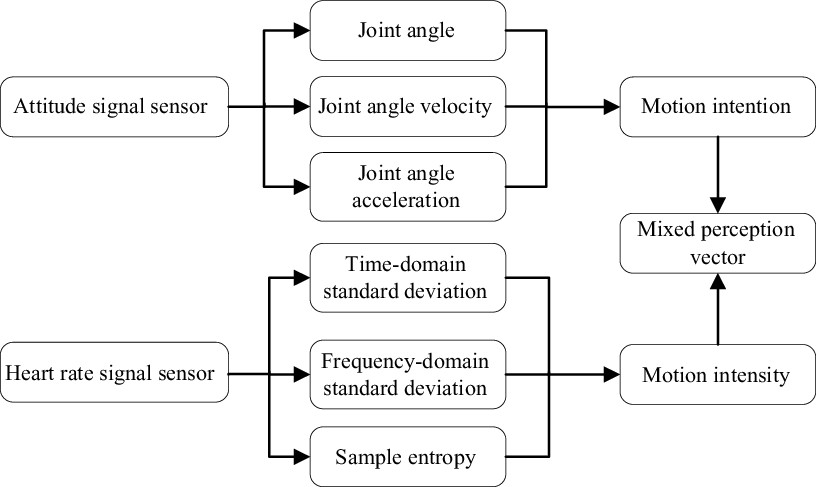
The multimodal fusion perception vector is designed as shown in Fig. 1, which is based on the concept of mixing motion intention and motion intensity as model input. The angle, angular velocity, and acceleration information of human upper limb joint are collected directly by the attitude signal sensor to evaluate motion intention. The heart rate information is collected by the heart rate signal sensor, and the time-domain standard deviation, frequency-domain standard deviation, and sample entropy are collected through feature engineering for evaluation of motion intensity. First, the time-domain standard deviation is obtained as
 \begin{equation} \mathrm{SD}=\sqrt{\frac{{\sum }_{i=1}^{N}\left| x_{i}-\mu \right| ^{2}}{N}} \end{equation}
where x i is the pulse waveform signal value collected by the heart rate sensor; N is the time series sampling points of the current sliding window; and μ is the average value of the current sliding window signal. In addition, considering the periodicity and real-time performance of heart rate signal, the high-frequency noise is filtered by using fast Fourier transform and modulus operation, and the frequency-domain standard deviation is calculated.
Schematic diagram of mixed vector construction.

Sample entropy is a method to measure the complexity of time series. It is widely used in the process of heart rate signal processing and can well characterize the sequence complexity of heart rate information [Reference Zarei and Asl35, Reference Porta, Bari, De Maria, Cairo, Vaini, Malacarne, Pagani and Lucini36]. For time series
 $\left\{x\left(n\right)\right\}=x\left(1\right),x\left(2\right),\ldots,x\left(N\right)$
with length N, it is reconstructed as
 $X_{m}\left(1\right),\ldots,X\left(N-m+1\right)$
, where
 $X_{m}\left(i\right)=\left\{x\left(i\right),x\left(i+1\right),\ldots,x\left(i+m-1\right)\right\}$
. The absolute value of the maximum difference between
 $X_{m}\left(i\right)$
and
 $X_{m}\left(j\right)$
is calculated as
 \begin{equation} d\left[X_{m}\left(i\right),X_{m}\left(j\right)\right]=\max _{k=0,\ldots,m-1}\left(\left| x\left(i+k\right)-x\left(j+k\right)\right| \right) \end{equation}
For a given
 $X_{m}\left(i\right)$
, count the number of
 $j\left(1\leq j\leq N,j\neq i\right)$
whose distance between
 $X_{m}\left(i\right)$
and
 $X_{m}\left(j\right)$
is less than or equal to r, denoted by
 $B_{i}$
, and determine
 ${B}_{i}^{m}\left(r\right)$
and
 $B^{\left(m\right)}\left(r\right)$
as
 \begin{equation} {B}_{i}^{m}\left(r\right)=\frac{1}{N-m-1}B_{i} \end{equation}
 \begin{equation} B^{\left(m\right)}\left(r\right)=\frac{1}{N-m}{\sum }_{i=1}^{N-m}{B}_{i}^{m}\left(r\right) \end{equation}
Increasing the dimension to m + 1, similarly
 \begin{equation} {A}_{i}^{m}\left(r\right)=\frac{1}{N-m-1}A_{i} \end{equation}
 \begin{equation} A^{\left(m\right)}\left(r\right)=\frac{1}{N-m}{\sum }_{i=1}^{N-m}{A}_{i}^{m}\left(r\right) \end{equation}
When N is finite, sample entropy is defined as
 \begin{equation} \text{SampEn}\left(m,r,N\right)=-\ln \left[\frac{A^{\left(m\right)}\left(r\right)}{B^{\left(m\right)}\left(r\right)}\right] \end{equation}
Finally, the mixed perception vector is collected by fusing the collected six-dimensional information at feature level and is used as the input of the mixed perception model.
2.2. Mixed perception vector data collection
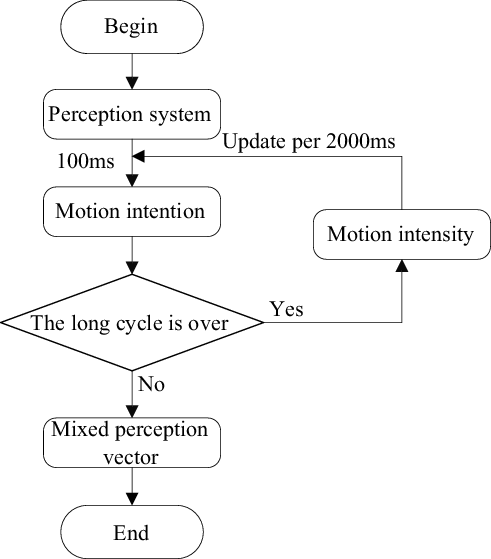
In the process of collecting signals, the difference between motion intention and motion intensity information should be fully considered. The control system carrier in this paper is a 6-DOF upper limb exoskeleton in the laboratory. Motors at joint are the disc actuator of INNFOS, and its control cycle is 100 ms. However, it is too short to extract heart rate information to reflect motion intensity. In order to solve this problem, a double cycle input method is adopted for the mixed perception model. The control cycle is divided into two layers, the first layer is short cycle of 100 ms, and the second layer is long cycle of 2000 ms. The sampling rate of attitude information and heart rate information in perception system are both 1000 Hz. When collecting the multimodal information vector, the system updates attitude information and eigenvalue of heart rate information every 100 and 2000 ms, respectively. The process of double cycle input method for the mixed perception model is shown in Fig. 2. During the operation of system, the attitude information is collected in each short cycle and eigenvalues of heart rate information are collected in each long cycle. After collecting the information required, fuse the information at the feature level and transfer it to PC for processing and preservation.
Schematic diagram of model double period input.

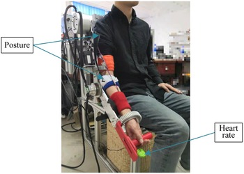
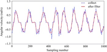
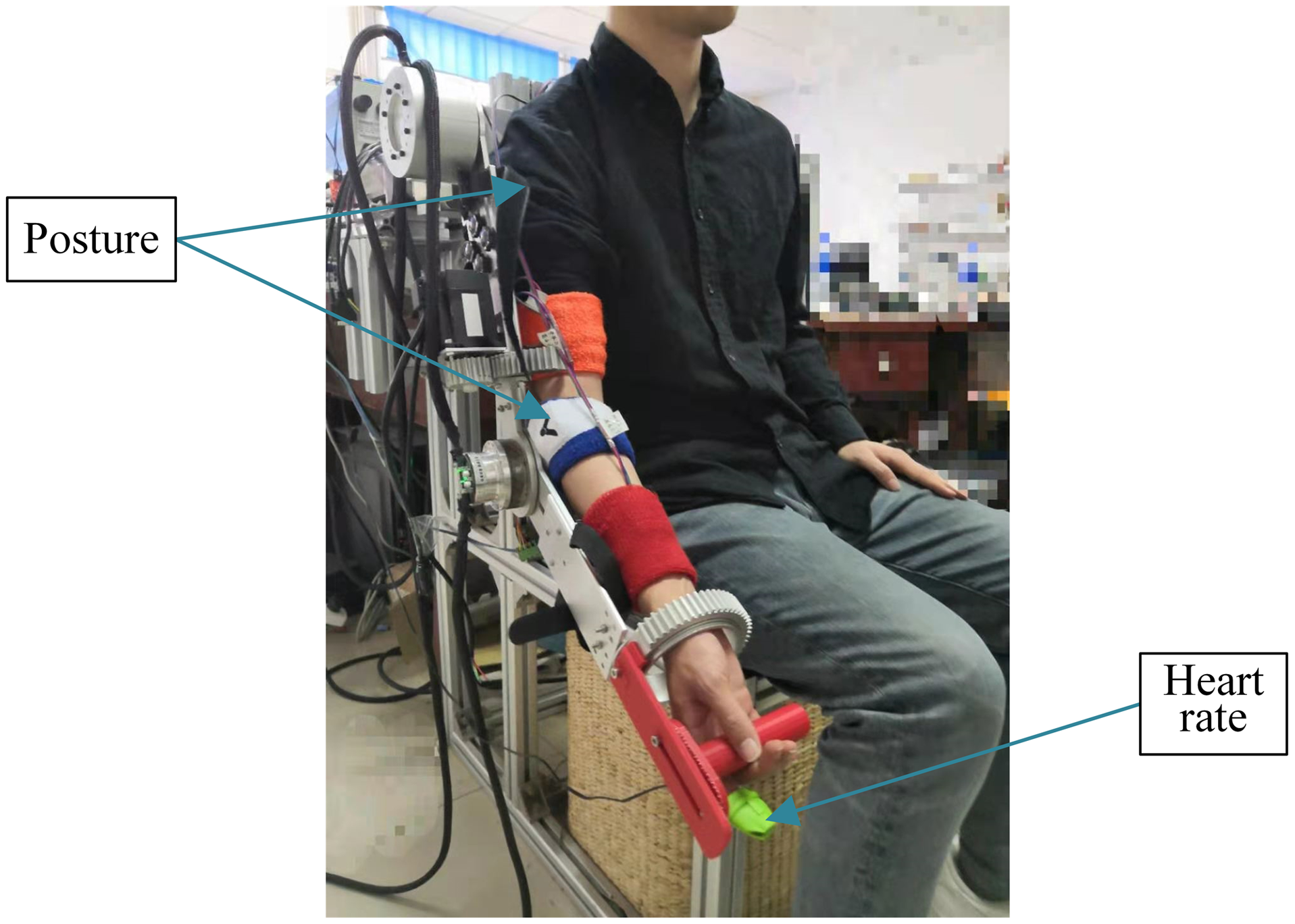
The layout of sensors is shown in Fig. 3. In this paper, the finger clip photoelectric pulse sensor heart rate clamp is selected and worn on fingertip to collect the heart rate signal. Compared with electrocardiograph, it is compact and does not affect the rehabilitation training effect. It can obtain pulse waveform by detecting the changes of blood absorption of near infrared light during pulse beating. The signal is converted into digital signal through filtering, amplification, and A/D conversion, and then input to the perception system through serial port transmission. The 9-axis IMU sensors WT-901C produced by WitMotion Company are selected as the attitude signal sensor, which is placed at the shoulder and elbow joints, respectively. In order to solve the problem of large fluctuation of angular velocity and acceleration information caused by external disturbances and sensor working conditions, the fourth-order Butterworth filter is used to filter its high frequency noise. Set low pass cutff frequency
 $f_{c}=10\,\mathrm{Hz}$
, the transfer function is
 \begin{equation} \left| H\left(\omega \right)\right| ^{2}=\frac{1}{1+\left(\omega /\omega _{c}\right)^{2N}} \end{equation}
where N is the order of Butterworth filter, N = 4;
 $\omega _{c}$
represents the cutoff angular frequency,
 $\omega _{c}=2\pi f_{c}$
. The angular velocity collection information is shown in Fig. 4.
The layout of sensors.
Angular velocity information collection.

3. Mixed perception model of motion intention and motion intensity based on LSTM
In the process of predicting the motion state of human upper limb, the motion intensity information and human joint motion information cannot be described by a linear model, which makes relationship between the mixed perception vector and joint trajectory nonlinear. In order to ensure accuracy of the trajectory prediction model, it is essential to find an appropriate nonlinear algorithm as its kernel when establishing the mixed perception model. The algorithm needs to meet the following requirements:
-
1. The input of the model is multidimensional time series information, and the output is trajectory information, Therefore, the algorithm needs to be suitable for processing time-series information.
-
2. The input of the model is real-time attitude information and heart rate information, and the algorithm output needs to be predictive to eliminate the time delay in the process of data collection.
-
3. There is a relationship between heart rate information and human motion state; however, no equation can directly show the relationship between these until now. Therefore, the algorithm needs to have strong applicability and trainability.
Finally, the LSTM, a branching model of recurrent neural network (RNN), is selected as the core algorithm of the mixed perceptual model. The biggest difference between LSTM and ordinary RNN is its unique gating mechanism [Reference Gers, Schmidhuber and Cummins37]. There are several significant components that control a LSTM cell, such as forget gate, update gate, and output gate, and these unique “gates” give LSTM the ability to forget and update timely.
3.1. Forward and back propagation of LSTM neural network
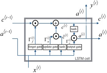
In the process of LSTM neural network forward propagation, a basic LSTM cell is first built. The LSTM cell has its unique gating mechanism as shown in Fig. 5. Where Γ <t> f is the forget gate, Γ <t> u is the update gate, and Γ <t> o is the output gate. The input is x <t> , and the output is y <t> . c <t> is the hidden state of the cell, a <t> is the memory state of the cell. Through the above gating mechanism, exoskeleton can switch and update motion state timely.
Schematic diagram of LSTM cell.

There are many states in the process of human upper limb motion, such as swinging upward, downward, and stop, also include acceleration, deceleration, and uniform speed. The purpose of this article is to ensure trajectory prediction accuracy under continuous switching of different motion states, which is also one of predominant characteristics of the LSTM neural network. Based on the process of exoskeleton switching from swinging upward to swinging downward, main components of LSTM cell are briefly introduced.
(1) Forget gate
When the upper limb exoskeleton switches from swinging upward to swinging downward, the forget gate is designed to delete the memory value of previously stored swinging upward state.
 \begin{equation} {\Gamma }_{f}^{\lt t\gt }=\sigma (W_{f}[a^{\lt t-1\gt },x^{\lt t\gt }]+b_{f}) \end{equation}
 \begin{equation} \sigma \left(t\right)=\frac{1}{1+e^{-t}} \end{equation}
where W f is the weight of the forget gate, b f is bias vector, and σ represents the activation function of sigmoid.
(2) Update gate and update cell
When the exoskeleton “forgets” swinging upward state, the update gate is applied to update its state for reflecting the current motion state.
 \begin{equation} {\Gamma }_{u}^{\lt t\gt }=\sigma (W_{u}[a^{\lt t-1\gt },x^{\lt t\gt }]+b_{u}) \end{equation}
where W u is the weight of the update gate, and b u is the bias vector.
In order to update the system state, a new vector needs to be created and added to the previous cell state. The formula for updating the cell is
 \begin{equation} {c}^{\lt t\gt }=\tanh \left(W_{c}\left[a^{\lt t-1\gt },x^{\lt t\gt }\right]+b_{c}\right) \end{equation}
 \begin{equation} \tanh \left(t\right)=\frac{1-e^{-2t}}{1+e^{-2t}} \end{equation}
where W
c
is the corresponding weight of the update cell, b
c
is the bias vector, and
 $\tanh$
represents the function shown in Eq. (13).
Combined with the update gate and the update cell, the update state of the cell can be formulated as
 \begin{equation} c^{\lt t\gt }={\Gamma }_{f}^{\lt t\gt }c^{\lt t-1\gt }+{\Gamma }_{u}^{\lt t\gt }{c}^{\lt t\gt } \end{equation}
(3) Output gate
Equations (15) and (16) can determine which output to use
 \begin{equation} {\Gamma }_{o}^{\lt t\gt }=\sigma (W_{o}[a^{\lt t-1\gt },x^{\lt t\gt }]+b_{o}) \end{equation}
 \begin{equation} a^{\lt t\gt }={\Gamma }_{o}^{\lt t\gt }\cdot \tanh (c^{\lt t\gt }) \end{equation}
where W o is the weight of output gate, b o is the corresponding bias vector, and a <t> is the memory state output of LSTM cell.
The forward propagation of LSTM neural network is composed of several LSTM cells in series, and the number of cells is related to the time step of program operation. In the process of exoskeleton operation, the mixed perception vector is input into perception model in current cycle to obtain the trajectory of next cycle, which is accomplished by the forward propagation of LSTM neural network.
In the process of LSTM neural network training, the weight of the model needs to be updated continuously through iterative calculation until the loss function reaches the global minimum or local minimum. In order to complete the process of weight update, calculation of the partial derivative of model is necessary for most optimization algorithms, which is completed by back propagation. The back propagation process of LSTM neural network is more complex than that of RNN, and the main changes are the additional gating mechanism: forget gate Γ <t> f , update gate Γ <t> u , and output gate Γ <t> o . Similar to forward propagation, it is necessary to start with LSTM cell when understanding back propagation, and the back propagation of entire neural network is composed of several cells in series. The back propagation process is completed by the Python Keras framework, which is not repeated here.
3.2. Construction of mixed perception model based on LSTM neural network
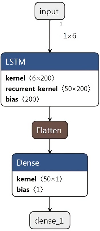
Due to its unique double-layer input mechanism, the mixed perception model based on LSTM neural network designed in this paper needs to discard the data of the first long period in the process of training neural network, that is, the data after the first long period (2 s) is included in the training data set. In the process of single joint training, the input of perception model is six dimensions, and the final output is one dimension angle information. The training of mixed perception model bases on Keras 2.0 framework of Python 3.7, which can build LSTM neural network quickly. Data collection is completed by the perception system, which stores the collected information in the form of .txt. The weights of the trained neural network are stored in the form of .h5, and then converted into C++ readable .txt file to facilitate the replication of the forward propagation of LSTM neural network.
Figure 6 shows the structure of multinetwork superposition model. The first layer is LSTM layer, whose parameters are shown in Table I. The second layer is flatten layer, which is used for the transition between the LSTM layer and the fully connected layer. It is used to flatten input vector, namely to transform the multidimensional data into one dimension. The third layer is dense layer, namely the fully connected layer, which is used to output the trajectory prediction results. According to the LSTM cell shown in Fig. 5, the LSTM layer is applied to update parameters a <t-1> , c <t-1> , a <t> , and c <t> , the dense layer is applied to update the prediction of y <t> , and the flatten layer is used for smooth transition between the two layers. According to the model constructed in this paper, there are 11,400 parameters in the LSTM layer, including the weight matrix and bias vectors of each gate, and the initial values of a <0> and c <0> . Since the output of the LSTM layer is already one-dimensional vector, number of parameters of the flatten layer for this model is 0. The dense layer has 51 parameters, including one-dimensional weight vector and bias vector.
Schematic diagram of multinetwork superposition model.

Parameter of LSTM neural network.

3.4. Training and testing of mixed perception model
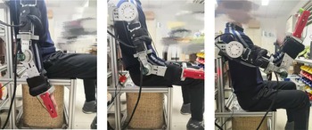
The control system designed in this paper aims to perceive the motion intention and motion intensity of patients with upper limb muscular weakness and assist them during rehabilitation training. According to the application scene, the action of drinking water is selected as the basic training motion, as shown in Fig. 7, which is a common arm motion in daily life. In order to simulate patients with upper limb muscular weakness, five healthy volunteers (22–24 years old) are selected to wear sandbags for simulation training. The proper weight sandbag (2 kg) is selected. Sandbag 1 is bound to the junction of exoskeleton forearm and wrist, and sandbag 2 is bound to the middle of exoskeleton upper arm as shown in Fig. 7.
Schematic diagram of training motion.

In the process of sample collection, human upper limb trajectory should be collected first. Volunteers wear exoskeleton and sandbags and move according to the instructions without the assistance of exoskeleton, which is used to simulate patients with upper limb muscular weakness. At the same time, the disc motor records the angle of the joint. A set of experiments is set for 240 s. During the experiment, the volunteers are required to repeat the training action, and then rest for the next set of experiments. Each volunteer carries out five groups of experiments. By collecting data from multiple volunteers, various states of human upper limb swinging can be generally collected, which makes the training set of the mixed perception model more comprehensive, and improves the universality of the model from the step of data collection. To improve the accuracy of the model, the data of five volunteers are combined, and 2000 sets of data are selected for each volunteer. Therefore, there are 10,000 sets of data for the mixed perception model in this paper. The first 8000 sets of data are selected as the training set, the second 2000 sets of data are selected as the testing set, and the training frequency is set to 2000 steps.
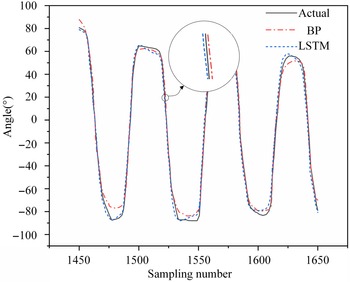
In order to compare and verify the effectiveness of the model proposed, the back-propagation (BP) neural network is used as the core algorithm of the model to predict the trajectory for comparison. The trajectory prediction results of the different models are shown in Fig. 8. It can be seen from the figure that the prediction accuracy of the model based on LSTM is better than that based on BP and the average trajectory prediction accuracies
 $\delta$
calculated by using the relative root mean square error are 95.3% and 89.1%, respectively.
 \begin{equation} \delta =\left(1-\frac{{\sum }_{i=1}^{N}\left(\left| {y}_{i}-y_{i}\right| \right)}{{\sum }_{i=1}^{N}\left(\left| {y}_{i}\right| \right)}\right)\times 100\% \end{equation}
where
 ${y}_{i}$
is the ith actual trajectory collected and
 $y_{i}$
is the ith predicted trajectory of model. The maximum error of the BP-based model is also larger. The maximum local errors are located at the peak and trough, which are 4.91° and 11.05°, respectively. In addition, it can be learned from the zoom view of figure that the model based on LSTM neural network has better real-time performance, and the predicted trajectory is slightly ahead of the actual trajectory, which is caused by the characteristics of LSTM neural network. Based on the mixed perception control method, the predicted trajectory is smooth and stable, and the overall trend of the predicted curve is same as that of the original collected trajectory.
When using LSTM neural network for trajectory prediction, the six-dimensional multimodal information vector collected at the current time step is taken as the input of the model, and joint rotation angle recorded by the disc motor of next time step is taken as the output, which makes the model itself has certain predictability. Therefore, the trajectory information input to the motor position loop is exactly the trajectory to which the next time step motor should move, which just eliminates the time-delay error in the data collection process and improves the real-time performance and accuracy of position control. After testing, the running time of the algorithm of data collection, multimodal information fusion, and trajectory prediction based on mixed perception model is about 1500 ms, less than the first data collection cycle (2000 ms) in which collected data are discarded, and the thread resource occupancy rate meets the expectation. Therefore, the designed method is feasible to be used for prediction of patients’ upper limb trajectory.
Partial trajectory prediction comparison.

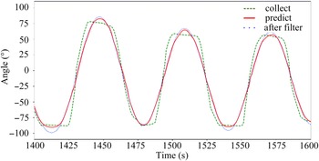
The prediction result above is based on the unfiltered trajectory data. In the process of collecting original trajectory data, due to the jitter of the sensors and effects of sensors accuracy, there will be some disturbances and affect smoothness of the trajectory. In order to filter out the external disturbance factors, reduce the effect of sensor accuracy and simulate a smoother trajectory, the collected original data are processed by fourth-order Butterworth filter and input into the trained LSTM neural network model in Fig. 9, where the green dash line is the original trajectory, the blue dash line is the trajectory after filtering, and the red curve is the prediction trajectory. It can be learned from Fig. 9 that the trajectory after filtering presents a sine-like curve after filtering, and similar to the predicted trajectory curve. With the filtered trajectory data as the input, the predicted trajectory is smoother, but compared with the original trajectory, the position error of trajectory curve is significantly increased.
Partial trajectory prediction after filtering.

As shown in Fig. 9, although there are large errors in several crests and troughs, they all have one characteristic: the extreme points of the prediction curve are closer to the original trajectory curve than the filtered trajectory curve. This is because the input of the perception model in this paper is a multimodal vector based on attitude and heart rate information, which is not only determined by the joint trajectory alone but also the eigenvalues of heart rate information. Here, only the trajectory information is filtered, other information does not change. The comprehensive influence of multidimensional information leads to difference between the filtered trajectory and prediction results in some positions. Human motion in exoskeleton is a complex human−robot collaborative motion process, and some unexpected conditions will cause dimension distortion in the multidimensional vector. Due to the multidimensional characteristics of the mixed perception vector, the error of the prediction trajectory can be reduced to a certain extent, which also ensures that the system can remain a stable state when sensors receive interference or the sensitivity decreases.
The phenomenon above confirms the robustness of the mixed perception model to a certain extent: the output of the predicted trajectory is determined by the multidimensional vector, and the change of data in a certain dimension cannot completely affect result of trajectory prediction.
4. Experimental research on control method based on mixed perception model
After constructing the trained mixed perception model, build the control system for implementing tests. In order to prevent human body injury caused by exoskeleton, the offline testing analysis is implemented to verify the accuracy and safety of the method. Then online testing is carried out to verify the real-time and effectiveness.
4.1. Offline testing of mixed perception model
The mixed perception model constructed in this paper is to predict the trajectory of human upper limb joint which is very flexible. Even in the process of simple arm lifting, there will be different states such as abrupt acceleration, deceleration, and uniform speed. In order to simulate human upper limb motion more realistically and verify adaptability of the model, the offline testing is implemented. Similarly, with water drinking as the training action, volunteers need to carry sandbags for rehabilitation training within a specified time (240 s) when collecting the training set data. The mixed perception model above includes a total of five volunteers’ motion intention and motion intensity information. In order to verify the universality of the model, volunteer A (24 years old) who did not participate in the collection experiment is reselected as offline testing experimenters.
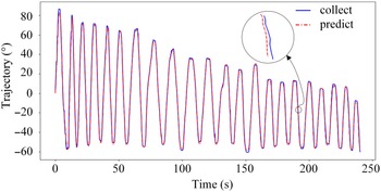
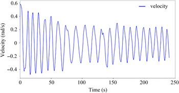
Compare collection trajectory with predicted trajectory of volunteer A’s elbow joint as shown in Fig. 10. It can be learned that with the increase of training time and times, the peak value of volunteer training action is gradually reduced, and the swing amplitude of upper limb is gradually reduced, mainly in the rising peak value. The circle in Fig. 10 is an enlarged partial trajectory drawing. It can be observed that the predicted trajectory is basically consistent with the collected trajectory, and there is a tendency to advance. Figure 11 is the collected speed curve. It can be seen from that the fluctuation amplitude of the velocity gradually decreased, and the acceleration gradually decreased. After the decrease of the swing amplitude in the later stage, the velocity rebounds.
Elbow joint trajectory of volunteer A.

Elbow joint velocity of volunteer A.

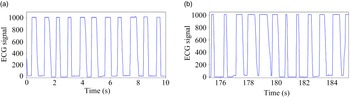
During the exercise, with the gradual increase of motion intensity, volunteers feel tired, and the frequency of heart rate accelerates and loses regularity to a certain extent. Figure 12 shows the heart rate signal (pulse waveform) of volunteer A. At the initial stage of training, the peak value and phase of pulse waveform of A are stable, as shown in Fig. 12(a), indicating that the heart rate is stable and the physiological condition is well. After a period of training, the pulse waveform is no longer as stable as in the initial stage, and the heart rate is higher than that in the initial stage within the same period (10 s), with 11 heartbeats in the initial stage and an increase to 12 heartbeats in the latter stage, as shown in Fig. 12(b).
(a) Heart rate information of volunteer A in the initial stage (b) Heart rate information of volunteer A in the latter stage.

Combined with Figs. 10–12, it can be seen that with the increase of training time and times, the heart rate and motion intensity of the subjects gradually increase, the exercise amplitude gradually decreases, and the exercise ability gradually weakens. This further illustrates the correlation between heart rate signal and motion intensity and proves the significance of considering motion intensity for achieving accurate trajectory prediction of patients. At the same time, it is verified that the mixed perception model is stable and universal through the above offline testing experiments.
4.2. Experimental study on control method based on mixed perception model input
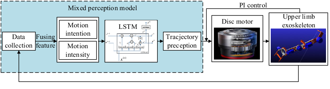
After completing the offline test verification of the perception model, the online control experiment is carried out. The control method is designed based on the laboratory 6-DOF exoskeleton, as shown in Fig. 13. First, the motion intention and motion intensity information are collected by sensors and input into the mixed perception model to get the predicted trajectory. Then, the motors get the motion instruction to drive the exoskeleton, and coding disks return the angle and angular velocity information to form a closed-loop negative feedback system through PI control. The mixed perception model trained by Python is reproduced by C++, and the sequential neural network model is reproduced in the control program by reading the weight parameters stored in the txt file.
Schematic diagram of exoskeleton control method based on mixed model of motion intention and motion intensity.

Volunteer B (23 years old) who did not participate in the above experiment is selected for online verification experiments, and each set of experiments is separated for 5 min to avoid fatigue. In order to simulate different states of human muscular weakness, four groups of experiments are set up: no sandbags, forearm bound sandbags, brachium bound sandbags, and both forearm and brachium bound sandbags. The position of sandbags is the same as the model training stage above.
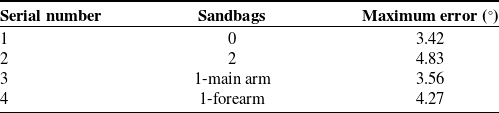
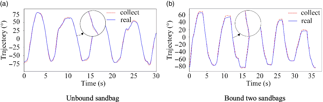
Figure 14(a) and (b) show the comparison of elbow joint motion trajectory and motor output trajectory of volunteer B in two cases of unbound sandbag and bound two sandbags, respectively. In the figure, the red dash line represents the upper limb trajectory data collected by volunteers B wearing attitude sensors, and the blue solid line represents the data collected by the coding disk after motor receives the predicted trajectory. As shown in Fig. 14, the actual trajectory track of the motor is the same as the motion trend of the data collected by volunteer B, and the predicted trajectory is basically consistent with the actual trajectory. The maximum error occurs at the peak and valley. In addition, with the increase of load, the trajectory of volunteers becomes steep and the motion amplitude decreases. The maximum error under different conditions is counted, and the results are shown in Table II. It is worth noticing that the maximum errors of trajectory prediction by the model are all less than 5°.
Experimental results of trajectory prediction.

Trajectory prediction experiment of volunteer B. (a) Unbound sandbag and (b) Bound two sandbags.

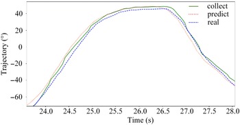
In order to further analyze the trajectory, a partial enlarged detail of trajectory is amplified, and the model prediction trajectory curve is added as shown in Fig. 15, where the green solid line is the trajectory of human upper limb collected by attitude sensor, the red dot line is the prediction trajectory of the model, and the blue dash line is the real trajectory returned by the motor encoder. It can be learned that compared with the predicted trajectory, the real trajectory is more stable and smoother than the data collected, and it is slightly lagged in the lifting stage and ahead in the falling stage. After analysis, the reasons of this phenomenon are mainly the following two points:
-
1. The motor trajectory is collected by the coding disk, and the process itself lags behind the motor operation. Therefore, the real collection trajectory is later than the upper limb trajectory.
-
2. Both the upper limb exoskeleton and human upper limb are affected by gravity. The motors receive position ring information and drive the exoskeleton, then drive the human upper limb movement. In the lifting stage, gravity will slightly affect the human−robot cooperative motion as a resistance. In the lowering stage, the direction of gravity and motion are at an acute angle, which will accelerate the process of motion.
The comparison of the collection trajectory, predicted trajectory and real trajectory of volunteer B.

5. Discussion
In this paper, aiming at the problem of single information collection and inaccurate motion state reflection of rehabilitation robot for patients, based on the existing 6-DOF upper limb rehabilitation exoskeleton robot in the laboratory, the heart rate and kinematics signals of patients are collected, and the mixed perception model of motion intention and intensity based on LSTM neural network is established. The control system construction and experimental analysis based on the mixed perception model are completed. The following conclusions are obtained:
-
1. In the process of rehabilitation training, motion intensity is relevant to the trajectory of patients’ upper limb. With the increase of motion intensity, patients feel fatigue, and the motion amplitude decreases. Therefore, considering human motion intensity during rehabilitation training is conducive to achieving more accurate trajectory prediction.
-
2. The mixed perception model based on motion intention and intensity can accurately predict the motion state of human upper limb, the average prediction accuracy can reach 95.3% and the joint angle error is within 5 degrees. The multimodal information fusion technology provides a more stable input for the perception model, which makes the model have good robustness and universality.
-
3. The mixed perception model based on LSTM neural network has certain predictability, which can be well applied to upper limb rehabilitation exoskeleton to solve the problem of kinematic signal delay and realize real-time trajectory prediction.
In the future, we plan to add sEMG signals to perceive the motion intention and fatigue degree of patients and further improve the control method to achieve a more comprehensive human−robot interaction.
Acknowledgments
This work was supported by the Natural Science Foundation of Shaanxi Province under Grant No. 2020JM-131 and the Fundamental Research Funds for the Central Universities under Grant No. 31020200503001.
Authors Contributions
Wendong Wang conceived and designed the study. Xin Wang and Dezhi Kong performed the experiments. Wendong Wang, Junbo Zhang, Chengzhi Zhao wrote the paper. Wendong Wang, Shibin Su and Xiaoqing Yuan reviewed and edited the manuscript. All authors read and approved the manuscript.
Declaration of Interest
The authors have no financial or proprietary interests in any material discussed in this article.