Introduction
A log-periodic dipole antenna (LPDA) is a unidirectional form of a log-periodic antenna. It evolves from log-periodic-toothed trapezoidal antennas [Reference Smith1] by folding its two arms to make the included angle zero. Thus, while angles do not entirely describe an LPDA, it depends on angular coordinates. The initial development of an LPDA was by IsBell [Reference DuHamel and IsBell2, Reference IsBell3]. Later, Carrel [Reference Carrel4] proposed modification with a detailed study on LPDAs. Following this, LPDAs are well reported in the literature, particularly due to its directivity, wider bandwidth, and higher gain. The physical design of LPDAs uses a constant scaling factor (τ) between its successive elements and the distance between them. The electrical excitation of an LPDA requires feeding of progressive elements with 180° phase difference to realize broadband operation. End-fire radiation patterns characterize LPDAs [Reference DuHamel and IsBell2–Reference Carrel4].
Microstrip antennas, being inherently narrowband, are natural candidates for adopting this concept for broadband operation. In [Reference Pues, Bogaer, Pieck and Van De Capelle5], a simple coplanar microstrip series feeding network excites log periodically scaled patch elements. It includes a model that predicts input impedance and radiation patterns as a function of frequency. An experimental study on inset-fed rectangular and triangular microstrip arrays is available in [Reference Dadel and Srivastava6]. In [Reference Rahim and Gardner7], a quasi-log-periodic antenna simulation is available. It uses square patches with an inset feed for impedance matching. It achieves a modest bandwidth. A single-layer log-periodic microstrip antenna (LPMA) with proximity-coupling to the feed line gives around 4 GHz bandwidth with 10.3 dBi gain [Reference Wu, Jin and Geng8]. In all these cases, the pattern is in the broadside direction, unlike LPDA.
Over the last decade, most of the reported work employing log-periodic principle has been on planar LPDAs. With printed planar helical dipoles as elements, the authors of [Reference Chen, Wu, Di and Hu9] obtained a compact LP antenna with 4 GHz bandwidth and gain better than 5.73 dBi. For size reduction, a Koch-dipole element is useful in LPDAs [Reference Anagnostou, Papapolymerou, Christodoulou and Tentzeris10].
Similarly, the use of trapezoidal-dipole elements in planar log-periodic antennas results in an operating band of 2–6 GHz [Reference Zengin11]. The use of Sierpinski-dipole elements in log-periodic antenna arrays for operation in L and S bands results in size reduction of around 50% compared to LPDAs [Reference Rajendran and Menon12]. A low-profile (~0.047λ at the lowest operating frequency) log-periodic array of cavity-backed slots fed by a meandered line [Reference Hu, Cao, Liu, Hua and Chen13] operates over a bandwidth from 6.9 to 17.4 GHz with good radiation characteristics. An eight-element log-periodic multiple-input multiple-output antenna for beam switching and dual-polarization characteristics [Reference Chen and Hong14] covers the ultra-wideband range with coupling isolation of more than 40 dB, the average peak gain of 6.5 dBi, and envelope correlation coefficient (ECC) < 0.005. An LPMA array with top parasitic loading using air gap is reported for broadcasting application [Reference Surjati, Alam and Ningsih15] which can tune the bandwidth by adjusting the air gap.
A rigorous analysis for a series-fed electromagnetically coupled overlaid patch array is available [Reference Hall16]. The design presented is complex due to the multilayer structure involving shorting posts on each radiating element. Moreover, it concludes that uniform substrate thickness limits the bandwidth enhancement. In [Reference Mishra17, Reference Muduli and Mishra18], transmission line models estimate the input impedance of a series-fed LPMA. An LPMA with radiating part consisting of a pair of patches with a Koch curve structure placed vertically on both sides of the dielectric plate operates from 4 to 12 GHz [Reference Ji, Wang, Nie and Jiang19]. A coplanar waveguide-fed LPMA with a defected ground plane for IoT applications, operating at 3.6 GHz, shows a gain of 9.36 dB [Reference Roges, Malik and Sharma20]. However, the LPMA do not resemble the structure and electrical characteristics of an LPDA to a large extent. Particularly, they show a broadside pattern while mostly the patches are on two sides of the main feed line.
This paper shows that LPMAs can be realized like LPDAs with log-periodic characteristics using appropriate feed design irrespective of substrate thickness.
Proposed LPMA design
Number of elements
The proposed design assumes that each element will have the same percentage of bandwidth (B). The desired operating frequency range of the array extends from f 1 to fN, with N number of elements. The frequency scaling is according to the log-periodic principle (i.e. f k/f 1 = τ 1−k). Under these conditions, simple algebraic operations using the LP principle suggest rounding up N (equation (1)) to the nearest upper integer gives the minimum number of elements:


In the above equation, we assume X as a variable and τ as the scaling factor of log-periodic antenna array.
Choice of scaling factor (τ)
A high-scale factor (τ), spanning the design bandwidth, can result in fewer elements. The frequencies for which antenna elements are absent show unacceptable S 11. It results in discontinuous gain over the bandwidth. On the contrary, a small-scale factor requires many elements, leading to a long distance between the branch line and the open-end, which worsens the impedance characteristics. A conservative range of choice for τ, following the LPDA design, is 1 ≤ τ ≤ 1.05.
LP array element
The LPMA literature shows simple scaling of the physical length and width of patches. It neither considers the dependence of the patch length on the patch width nor justifies the negligence of this dependence in scaling. Of course, it is negligible in comparison with the operating wavelength. However, its contribution is evident in improving resonant frequency through effective dielectric constant. Although the lower operating frequencies mask the impacts of the effective dielectric constant to a large extent, they are not so at higher frequencies. As the width is independent of other dimensions, there is no problem in scaling it directly. A simple rearrangement of the scaling relation for width gives the formula for determining the width of the kth element of the array:

As is well known, for a microstrip antenna, the effective dielectric constant, which is a function of its width, relates its physical length and electrical length. Accounting for the width through the effective dielectric constant, the length of the kth patch becomes

At lower frequencies, which do not need stringent accuracy (up to two decimal points on a centimeter scale), one can use simple scaling as available in the literature [Reference Pues, Bogaer, Pieck and Van De Capelle5–Reference Chen, Wu, Di and Hu9, Reference Mishra17, Reference Muduli and Mishra18].
Element placement
Mutual coupling reduction problem
In LPDAs, the electric dipoles are transversal to the direction of the feed [Reference IsBell3, Reference Carrel4], and the pattern is end-fire. The end-fire pattern plays a major role in the significant mutual coupling among the dipole elements, leading to a broadband response. On the contrary, there are two dominating sources of mutual coupling reduction in LPMAs. The LPMA arrangement of the elements and their connection to the feeding line leads to short-circuiting off-resonant elements close to the feed point. Thus, there can be a substantial reduction in the mutual coupling, affecting the proper operation of the array. Moreover, in LPMAs, each element is equivalent to a pair of magnetic dipoles, and with the traditional feed [Reference Pues, Bogaer, Pieck and Van De Capelle5–Reference Surjati, Alam and Ningsih15], these dipoles are parallel to the main feed line. As seen later from simulation, this results in a radiation pattern more aligned to broadside (i.e. H-plane), reducing electrical interaction (i.e. mutual coupling) among elements which affects the broadband (i.e. log-periodic) nature of the LPMA.
Compensating the mutual coupling reduction
The short-circuiting problem needs an impendence transformation to make it close to an open circuit for off-resonant points. For the kth array element, we use a branch line of length 3λgk/4. For the end-fire (i.e. E-plane) pattern, we introduce a 90° bend near the antenna element in the derived feed line (Fig. 1), making its radiating edges transversal to the main feed. Alternative array elements are on the upper and lower sides of the mainline. It ensures out-of-phase excitation between two consecutive elements, essential for a log-periodic antenna. Moreover, this also prevents any chance of overlapping two successive patches.
Schematic diagram of the proposed LPMA.

The distance between the originating points of these branch lines on the main feed line (Dk) and each portion of the 90° bends (“lk” and “dk”) obey the log-periodic scaling principle. So, we use the following formulae to find their length. The characteristic impedance of the mainline is 50 Ω, which gives its width. The branch line characteristic impedance is adjusted to transform the kth antenna element impedance to 50 Ω (i.e. mainline impedance) at frequency fk:


Design algorithm
The following is the design flow for an LPMA with scaling factor τ, element bandwidth percentage B, lower frequency fl, upper frequency fu, number of elements N, and branch feedline width wb:
(1) Read B, fl, and fu
(2) Assign τ randomly a value between 1 and 1.05
(3) Calculate N using f u/f 1 = τ 1−N
(4) Calculate fk using f k/f 1 = τ 1−k, k = 2 to N−1
(5) Calculate the minimum number of elements (Nmin ) using equation (1)
(6) Calculate the dimension of each element using equations (2)–(6)
(7) Obtain width of kth branch line (k = 1 to N) to transform the impedance of kth element to 50 Ω.
LPMA simulation and prototype
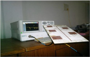
To test the proposed design method, the degree of resemblance between results from simulations and measurements on the prototype followed a comparison with the work of Gardener et al. [Reference Rahim and Gardner7] by reproducing their findings using electromagnetic simulation. The CST MWS, with 50 dB accuracy, was used to simulate and reproduce the results of Gardner et al. [Reference Rahim and Gardner7] for an LPMA which operates in the frequency range of 2.03–2.73 GHz (in the paper [Reference Rahim and Gardner7] S 11 plot is from 1 to 5 GHz). Assuming an optimistic bandwidth of 3% for each radiator, the minimum number of elements from equation (1) is three for this design. They had used seven and five elements which are well over this minimum value. The simulation preserved these numbers and other specifications (Table 1). A re-simulation followed with the proposed design without changing the specifications. As per the proposed design, the prototype (Fig. 2) was fabricated for testing the five-element LPMA due to constraints of available resources and facilities.
Five-element prototype LPMA.

Design specifications

Result and discussion
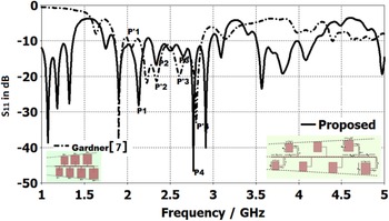
Table 2 shows the design parameters of the LPMAs with five (the shaded portion of the table) and seven elements. The square patch in [Reference Rahim and Gardner7] is for suppressing higher-order modes. The length is responsible for resonant frequency, so the side length of the square patch is close to that of the patch from the proposed method. However, due to the difference in the determination of dimensions, the lengths do not match. It results in mismatch of results from the two approaches, as evident from resonant peaks and return-loss plots (Fig. 3).
Comparison of S 11-parameters for the two configurations (shown in the inset).

Design parameters for LPMAs from [Reference Rahim and Gardner7] and the suggested method

PA, proposed antenna in this paper.
Frequency in GHz, all other are in mm.
L, W, length and width; wb, width of branch line.
In [Reference Rahim and Gardner7], L = W and I = inset depth for 50-Ω input impedance.
All values rounded off to two decimal points.
Figure 3 compares S 11 parameters for the seven-element LPMA in [Reference Rahim and Gardner7] with the proposed one. There are seven peaks in and around the desired band for the configuration of [Reference Rahim and Gardner7]. It can be due to the assumed principle that only the resonating element exists, under negligible mutual coupling, while design effectively open circuits others. The reason behind the other smaller peaks may be the weak mutual coupling, higher- order modes, and so forth. The lower peak is at 1.8 GHz, and the upper one is at 3.1 GHz instead of 2.03 and 2.73 GHz, respectively. It can be due to weak mutual coupling and excitation of orthogonal modes.
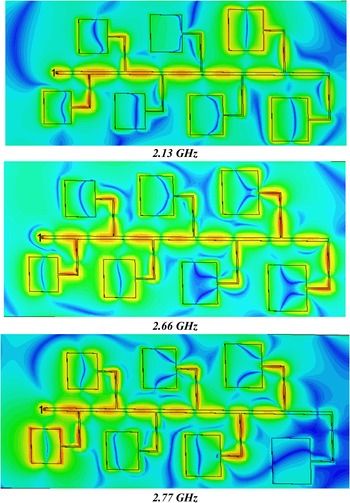
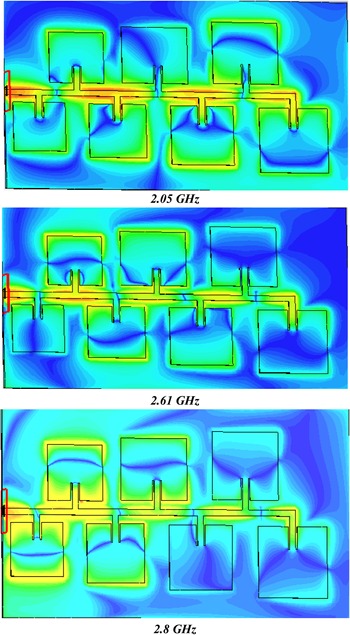
The proposed design also has seven peaks around the band of interest. Out of these, five are more prominent than those from [Reference Rahim and Gardner7]. Besides, there is also a small peak between the fourth and fifth peaks. Moreover, Fig. 4 shows the electric field distribution at 2.13, 2.66, and 2.77 GHz, which indicate the excitation of adjacent elements with the resonating one. These imply a not so weak mutual coupling effect, as in the case of [Reference Rahim and Gardner7] (Fig. 5).
Electric-field distribution in the proposed LPMA.

Electric-field distribution in traditional LPMA of [Reference Rahim and Gardner7].

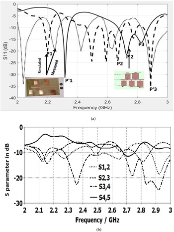
Figure 6 compares the radiation patterns of both the LPMA designs at selected peaks. For our proposed model (P1, P2, P3, and P4), the main lobe is directed closer to the end-fire direction (θ = 90°) than for the Gardner model (P′1, P′2, P′3, and P′4). The dip at θ = 90° is due to diffraction at the ground plane edge and will be characteristics of any end-fire antenna mounted on a finite ground plane. All patterns are linearly polarized. Thus, the proposed formulae and feed method take the design closer to true log-periodic characteristics while Gardner's fails to do so, as is evident from its non-end-fire radiation pattern. Figure 7 shows S parameters of five-element LPMA. It compares (Fig. 7(a)) the S 11 of the fabricated prototype and simulated ones and looks at theoretical mutual coupling for the proposed LPMA (Fig. 7(b)). Contrary to the expectation, for the simulated Gardner-type LPMA, there are only three prominent peaks. It also shows a smaller bandwidth. It happens as the designs of the fourth and fifth (largest) elements are for the two lowest frequencies, and the reduced mutual coupling between the elements is insufficient for coverage of the complete band.
Comparison of E-field patterns at resonant peaks, from left to right: P1, P′1 = 2.13, 2.05 GHz, P2 = P′2 = 2.34 GHz, P3, P′3 = 2.66, 2.61 GHz, P4, P′4 = 2.77, 2.8 GHz.

S-parameter for five-element LPMA: (a) comparison of S 11 simulated (proposed and [Reference IsBell3]) and measured and (b) simulated mutual coupling in the prototype.

Moreover, due to this, adjacent elements of the main resonator could not be excited sufficiently to become active; so, the active region cannot move along the array elements. The last two elements are farthest from the first two but nearer to the third element. So, their presence affects the resonant frequency of the third element, which shifts downward from that of the second resonant frequency. It leads to a band notch of around 0.3 GHz between the second (P′2) and third (P′1) operating bands.
However, as expected, there are five resonant peaks in Fig. 7(a) for the proposed design (simulated and measured). The explanation for this is shown in Fig. 7(b). It shows the S-parameters between different elements. It indicates an appreciable coupling between, at least two neighboring antennas throughout the band of interest. This figure also shows that the measured S 11 closely follows the simulated one. This apparent behavior is due to three reasons: (1) fabrication tolerances in the prototype, while simulations are for ideal values; (2) electromagnetic interference (EMI) in the measurement environment due to unavailability of an anechoic chamber; and (3) four times expansion of the frequency axis compared to Fig. 3.
Nevertheless, the mismatch indicates obtaining the desired radiation pattern may not be possible. Figure 8 shows radiation patterns of the LPMA prototype for further discussion of this issue. As shown in Fig. 6, the traditional (i.e. Gardner) feed maintains a broadside pattern in the simulation (Fig. 8(a)). Both simulation and measurement results on the prototype show that the E-plane radiation patterns are toward the end-fire direction.
E-plane radiation pattern: (a) comparison of simulated patterns and (b) measured with prototype.

Besides, the proposed design also shows out-of-band resonant peaks. These may be due to spurious radiation due to sharp bends and junctions in the branch line (particularly at lower frequencies below the dominant frequency of the largest patch). These may be mostly due to the excitation of higher-order modes at the upper end. Embedding suitable filters in the main feedline can suppress such spurious peaks. In [Reference Rahim and Gardner7], the design aims at radiation only from resonating elements by reducing their mutual coupling with neighboring elements.
Conclusion
This study developed a design technique for LPMAs to operate like LPDAs. It considered characteristics of LPDAs and compared them with different pre-existing LPMA designs (Table 3). Analyzing differences in characteristics, new LPMA designs gradually evolved until obtaining a satisfactory design. In the final design, LPMA elements have a common axis of alignment with appropriate feeding so that the phase difference between the two consecutive elements is 180°. The final design gives an almost end-fire pattern (θ ≈ 70°) with a gain of 9.8 dBi. In the 2.2–3 GHz range, the fabricated prototype of five elements shows four resonant peaks (2.23, 2.45, 2.65, and 2.91 GHz) with errors of (1.34, 2.4, 1.52, and 0.35%) compared to simulated results. The differences between the measured and simulated results can be due to the measurement and fabrication tolerances, and unavailability of the anechoic chamber for measurement. As this antenna exhibits a gain of 9.8 dBi with impendence bandwidth from 2.2 to 3 GHz, it is suitable for Bluetooth, ZigBee, wireless LANs, and satellite radio communication.
LPMA model comparison

 Arjuna Muduli was born in India in 1985. He is an associate professor in the Department of Electronics and Communication Engineering at KLEF (Deemed to be University), Vijayawada, AP-522502, India. He has received his Ph.D. degree from Berhampur University, Odisha. His research interest includes RF and antennas, wireless communication, software-defined radios, and cognitive radios. He worked as a DST INSPIRE fellow (Govt. of India) from 2011 to 2016. He qualified UGC NET (Govt. of India) in 2012. He has received Gold Medal for acquiring first position in both M.Tech. and M.Sc. programs. He is a fellow of IETE, India and a senior member of IEEE.
 Rabindra K. Mishra was born in India in 1963. He is a professor in the Electronic Science Department of Berhampur University. He has researched extensively in the areas of planar antennas and applications of soft-computing techniques for analysis and design of planar antennas. He had visited the University of Birmingham as a British Commonwealth Fellow during 1999–2000. He has supervised 10 doctoral theses. He has published two monographs and over 150 learned articles in journals of repute and proceedings of conferences, seminars, etc. These publications have earned the IETE Sir J. C. Bose best application paper award (1999), Shri Hari Ohm Ashram Prerit Hariballabha Das Chunilal Research Endowment Award (2000), and Samanta Chandra Sekhar Award in Engineering & Technology (2008), which is the highest award by the Govt. of Odisha.