
I. INTRODUCTION
The high hardness, chemical and electrochemical inertness, and excellent wear resistance of amorphous carbon (a-C) films make them desirable overcoats for applications requiring protective ultrathin films, such as hard-disk drives, optical lenses, microelectromechanical systems, and surgical instruments. The good tribomechanical properties of a-C films originate from a relatively high content of tetrahedral (sp3) atom carbon hybridization, which controls the film density, elasticity, and hardness and is strongly depended on the film-growth conditions. Film deposition methods using energetic species as film-forming precursors, such as filtered cathodic vacuum arc (FCVA), Reference Brown1,Reference Zhang and Komvopoulos2 are particularly effective in producing ultrathin a-C films rich in sp3 hybridization. This is because the kinetic energy of film-forming C+ ions can be tuned by applying a pulsed substrate bias voltage to control direct/recoil ion implantation, sputtering of weakly bonded atoms, and film growth. However, partial backscattering of C+ ions and reduced ion bombardment onto the growing film surface at the end of the film growth process leads to the formation of a multilayered film structure consisting of interface and surface layers with relatively low and varying sp3 contents and an intermediate (bulk) layer rich in sp3 hybridization. Reference Wang and Komvopoulos3
Current trends in most of the above mentioned technologies necessitate ultrathin a-C films. For example, in contemporary hard-disk drives the physical spacing between the magnetic media of the hard disk and the read/write transducer embedded on the flying head must be ∼5 nm. Reference Robertson4,Reference Goglia, Berkowitz, Hoehn, Xidis and Stover5 To achieve such a small spacing, the a-C overcoat thickness must be ∼2–3 nm. However, because the structure of such ultrathin films is dominated by those of the weaker interface and surface layers, there are concerns about the uniformity, density, and protective capacity of these a-C films. Indeed, film thickness effects on the tribomechanical properties (e.g., elastic modulus and wear resistance) and sp3 content of carbon overcoats have been reported for films of thickness <4 nm. Reference Beghi, Ferrari, Teo, Robertson, Bottani, Libassi and Tanner6,Reference Zhong, Zhang, Luo and Lu7
Previous studies concerned with the adhesion of a-C films to different substrates have shown that substrate biasing promotes the intermixing of carbon with the substrate material, which is important for enhancing film adhesion to the substrate. Reference Sheeja, Tay, Lau and Shi8–Reference Rismani, Sinha, Yang and Bhatia10 However, this intermixing also induces structural and compositional changes in the near-surface region of the substrate, which may negatively affect the properties and structure of the substrate (e.g., magnetic media of hard disks) and also degrade the quality of ultrathin films because of the intense C+ ion bombardment onto the growing film during substrate biasing. Thus, it is necessary to develop a film deposition method that can produce ultrathin a-C films having an interface layer of minimum thickness and structures and properties predominantly controlled by the stronger sp3-rich bulk layer.
One of the main objectives of this study, therefore, was to develop a film deposition process that can overcome the aforementioned shortcomings. The idea was to synthesize bilayer ultrathin a-C films with structure and properties dominated by those of the stronger bulk layer. To achieve this objective, two process steps were incorporated in conventional FCVA a-C film deposition under optimum conditions of pulsed substrate biasing (−100 V substrate bias voltage): (i) a low ion energy pre-deposition step (zero bias voltage) leading to the formation of an ultrathin (<1 nm) carbon film and (ii) a post-deposition step of Ar+ ion sputtering resulting in film thinning (etching). A low C+ ion energy (zero bias voltage) leads to the formation of an extremely thin film, which acts as a buffer layer during the subsequent step of a-C film deposition under energetic C+ ion bombardment (−100 V substrate bias).
Another principal objective of this investigation was to examine the cross-sectional structure and composition of the synthesized bilayer a-C films using high-resolution transmission electron microscopy (HRTEM) and electron energy loss spectroscopy (EELS). To illustrate the capability of the present multistep FCVA process to produce ultrathin a-C films with structures and properties dominated by the sp3-rich bulk layer, representative HRTEM and EELS results of bilayer a-C films are contrasted with those of single-layer a-C films of similar thickness deposited under the same FCVA conditions of optimum substrate biasing. The obtained results are explained in the context of physical mechanisms (e.g., direct/recoil ion implantation, densification, and resputtering) encountered under optimum FCVA conditions of a-C film growth.
II. EXPERIMENTAL METHODS
A. Film synthesis
Glass substrates (1 × 1 cm2) sectioned from a 2.5 inch diameter disk, which was coated with a ∼100 nm thick NiTa layer, were loaded onto a custom-made FCVA system Reference Zhang and Komvopoulos11,Reference Zhang and Komvopoulos12 and etched for 6 min in vacuum (∼2 × 10⁻⁴ Torr) with a 500 eV Ar+ ion beam of 60° incidence angle (measured from the normal to the substrate surface), generated by a 64 mm Kaufman ion source (Commonwealth Scientific, Alexandria, Virginia). After allowing the substrate to cool down for 5 min and the vacuum chamber to reach a low base pressure (<5 × 10⁻⁷ Torr), plasma arcing was initiated at the cathode (99.99% pure graphite) surface by a mechanical striker. A cusp-configuration magnetic field was applied to the cathode to stabilize the plasma. Reference Zhang and Komvopoulos11 The potential and current between the graphite cathode and the anode were set at ∼24 V and ∼89 A, respectively. The magnetic field generated by electromagnetic coils having an out-of-plane S-configuration effectively removed any macroparticles and/or droplets expelled from the cathode, allowing only high purity (∼99.99%) C+ ions to reach the substrate. The current in the auxiliary, upstream, and downstream coils was set at 30.5, 30.9, and 29.6 A, respectively. For uniform sputter etching and radial film growth during Ar+ ion bombardment and film growth, the substrate was rotated at 60 rpm.
To control the C+ ion energy in the first process step (pre-deposition) used to produce an ultrathin interface a-C film, the substrate stage was oriented at an angle of 20° with respect to the incident C+ ions and subjected to a zero bias voltage. To obtain an interface a-C film of thickness <1 nm, the duration of this process step was fixed at 6 s. During the second process step (deposition), which also lasted for 6 s, an optimum pulsed bias voltage of −100 V and 75% duty cycle was applied to the substrate, which was oriented perpendicular to the incident C+ ions (i.e., 90° incidence angle) to promote ion subplantation in the interface film and sp3 hybridization in the bulk layer. Reference Xie and Komvopoulos13 The third process step (post-deposition) involved 500 eV Ar+ ion sputter etching for 6 min to reduce the a-C film thickness to 2–3 nm, as shown previously. Reference Xie and Komvopoulos14 The process conditions corresponding to the aforementioned process steps are summarized in Table I. For comparison, a single-layer a-C film was deposited in 12 s under optimum FCVA conditions (i.e., −100 V substrate bias voltage, 75% duty cycle, and 90° ion incidence angle) and thinned down to a thickness similar to that of the bilayer films by Ar+ ion sputter etching for 4 min.
Process conditions for synthesizing bilayer a-C films.

B. Microanalysis techniques
Cross-sectional HRTEM specimens were prepared by mechanical grinding, two-side dimpling, and surface finishing using ion milling. Before specimen bonding, a thin (5–10 nm) Au capping layer was sputtered onto the surface to distinguish the epoxy glue from the a-C film in the HRTEM images and the EELS signal of the a-C film from that of the carbon-based epoxy. More details about the HRTEM specimen preparation method used in this study can be found elsewhere. Reference Xie and Komvopoulos13,Reference Wan and Komvopoulos15,Reference Wang and Komvopoulos16
The HRTEM images and EELS spectra were obtained with a microscope (F20 UT, FEI Tecnai, Hillsboro, Oregon) operated at 200 kV, equipped with a CCD camera (2048 × 2048 pixels), which was positioned 42 mm behind a Gatan imaging filter. An EELS collection semiangle of 16.3 mrad, a 150 μm C2 aperture, and a 9.4 mrad C2 semiangle were used in these studies. The spatial resolution of scanning TEM (without a monochromator) is 0.14 nm. Using the full-width at half-maximum of the zero-loss peak, the energy resolution of EELS is found to be <0.58 eV, which, considering the band gap difference (0.8–0.9 eV) between sp2 and sp3, is adequate for distinguishing sp2 from sp3 hybridization.
III. RESULTS AND DISCUSSION
Cross-sectional HRTEM specimens were used to determine the a-C film thickness after each process step. Figure 1 shows cross-sectional HRTEM images of a-C films obtained after each process step. All images reveal a multilayered structure consisting of (i) NiTa layer, (ii) a-C film, (iii) Au capping layer, and (iv) epoxy glue. The average a-C film thickness corresponding to the first [Fig. 1(a)], second [Fig. 1(b)], and third [Fig. 1(c)] process step is equal to 0.9, 6.0, and 2.5 nm, respectively (Table I).
Cross-sectional HRTEM images of a-C films obtained after (a) forming an ultrathin carbon interface (buffer) film, (b) a-C film deposition, and (c) Ar+ ion etching. Differences in contrast and structure reveal: (1) NiTa layer, (2) a-C film, (3) Au capping layer, and (4) epoxy glue.

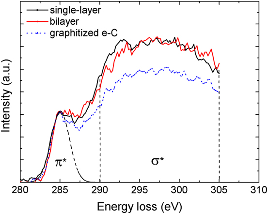
The cross-sectional structure of the a-C films was examined by analytical EELS, which uses the energy loss of beam electrons due to inelastic collisions with electrons of the specimen (target) atoms. Reference Williams and Carter17,Reference Egerton18 The high-energy-loss EELS range (>50 eV) yields insight into beam electron interaction with inner (core–shell) electrons of the specimen material. The characteristic C K-edge spectrum in the range of 280–305 eV can be used to determine the sp2 and sp3 contents. The pre-edge peak at 285 eV is attributed to electron excitation from the ground-state 1s core level to the vacant π*-like antibonding states, while the edge originating at 290 eV is associated with electron excitation from the 1s core level to the σ* states. Reference Cuomo, Doyle, Bruley and Liu19 The elemental film composition can be obtained from the analysis of the C K-edge spectra. The σ* peak was integrated from 290 to 305 eV (to minimize plural scattering effects), whereas the π* peak was fitted with a Gaussian distribution. The area ratio of these two peaks is proportional to the relative number of σ* and π* orbitals, which is 3/1 for 100% sp2 and 4/0 for 100% sp3. Therefore, the film content of sp2-bonded carbon atoms x is given by Reference Cuomo, Doyle, Bruley and Liu19
 $${{{{\left( {{{{\pi ^*}} \mathord{\left/ {\vphantom {{{\pi ^*}} {{\sigma ^*}}}} \right. \kern-\nulldelimiterspace} {{\sigma ^*}}}} \right)}_{{\rm{film}}}}} \over {{{\left( {{{{\pi ^*}} \mathord{\left/ {\vphantom {{{\pi ^*}} {{\sigma ^*}}}} \right. \kern-\nulldelimiterspace} {{\sigma ^*}}}} \right)}_{{\rm{std}}}}}} = {{3x} \over {4 - x}}\quad ,$$
where the standard (std) specimen is evaporated carbon (100% sp2). More details about the curve fitting approach and the calculation of the sp3 fraction can be found in previous publications. Reference Wang and Komvopoulos3,Reference Xie and Komvopoulos13
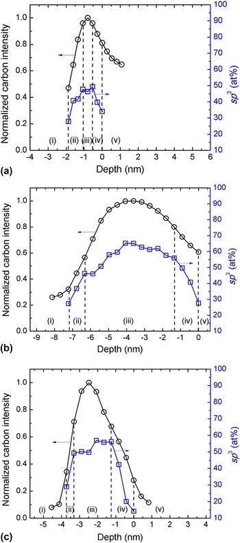
Figure 2 shows the cross-sectional a-C film structure after each process step. The normalized carbon intensity was obtained by dividing the EELS spectrum (integrated from 280 to 305 eV) by the maximum intensity of the depth profile. The sp3 content was calculated from the C K-edge spectra using Eq. (1). The carbon concentration and sp3 depth profiles reveal the existence of the following five regions: (i) substrate (the carbon intensity is weak because the signal originates from the NiTa layer), (ii) interface layer (both carbon concentration and sp3 content increase sharply), (iii) bulk layer (the carbon concentration reaches a maximum, whereas the sp3 fraction remains fairly constant), (iv) surface layer (both carbon concentration and sp3 content decrease sharply), and (v) capping layer (the weak carbon signal is due to adventitious carbon adsorbed onto the Au layer). The dashed lines indicate the boundaries between neighboring regions. The first process step led to the intermixing of the buffer film with the substrate to a depth of ∼0.8 nm and the development of a maximum sp3 content in the buffer film of ∼49 at.% [Fig. 2(a)]. While the second process step did not affect the sp3 content of the interface and bulk layers of the buffer film, the penetration of the buffer film by energetic C+ ions led to the increase of both carbon intensity and sp3 content, with the latter reaching a maximum of ∼65 at.% [Fig. 2(b)]. In the third process step, Ar+ ion irradiation caused significant thinning of the interface, bulk, and surface layers of the a-C film, accompanied by a decrease in sp3 content of the bulk layer, which resulted in a maximum sp3 content in the bilayer film of ∼57 at.% [Fig. 2(c)]. The effect of Ar+ ion irradiation is a manifestation of several physical mechanisms, e.g., knock-on/recoil implantation, densification, and resputtering, which have been discussed in detail in a previous study. Reference Xie and Komvopoulos14 Thus, the results shown in Fig. 2 indicate a sharp increase of the sp3 content of the interface layer and significant film thinning due to Ar+ ion sputter etching.
Depth profiles of normalized carbon intensity and sp3 content calculated from EELS spectra obtained after (a) forming an ultrathin carbon interface (buffer) film, (b) a-C film deposition, and (c) Ar+ ion etching. The dashed lines indicate the boundaries between neighboring regions.

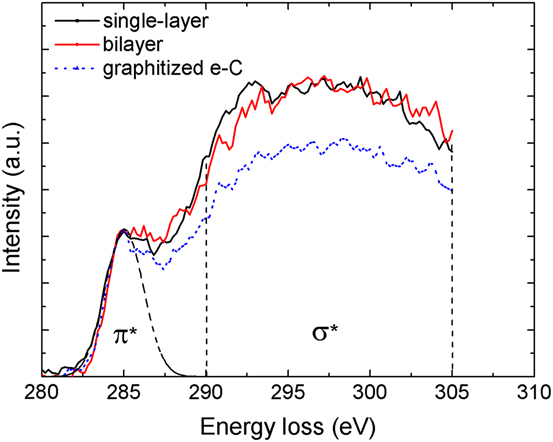
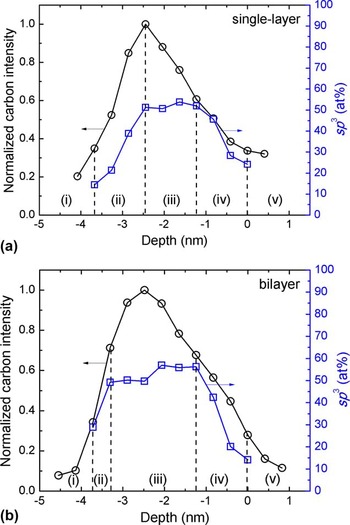
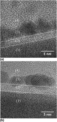
Figure 3 shows a comparison of cross-sectional HRTEM images of single-layer and bilayer a-C films of similar thickness. The images show the formation of multilayered structures similar to those shown in Fig. 1. Figure 4 shows C K-edge spectra of the bulk layer of single-layer and bilayer a-C films. The spectrum of the standard sample, i.e., evaporated graphitized carbon (e-C), is also included for reference. The π* peak was fitted with a Gaussian distribution from 282 to 287.5 eV, while the σ* peak was obtained by integrating the spectrum from 290 to 305 eV, as mentioned earlier. A comparison of the spectra indicates that the bulk layers of single-layer and bilayer a-C films possess similar structures. The corresponding depth profiles of normalized carbon intensity and sp3 content are contrasted in Fig. 5. The carbon concentration and sp3 depth profiles reveal the existence of five distinct regions, similar to those shown in Fig. 2. The bilayer a-C film possesses significantly thinner interface layer, much thicker bulk layer, and greater change (slope) in sp3 content through the interface layer compared with the single-layer a-C film.
Cross-sectional HRTEM images of (a) single-layer and (b) bilayer a-C films synthesized with the present method. Differences in contrast and structure reveal: (1) NiTa layer, (2) a-C film, (3) Au capping layer, and (4) epoxy glue.

C K-edge EELS spectra of the bulk layer of single-layer and bilayer a-C films synthesized with the present method. The spectrum of the standard sample consisting of evaporated graphitized carbon (e-C) is also included for comparison.
Depth profiles of normalized carbon intensity and sp3 content calculated from EELS spectra of (a) single-layer and (b) bilayer a-C films synthesized with the present method, revealing significant structural differences between the two films after Ar+ ion etching. The dashed lines indicate the boundaries between neighboring regions.

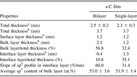
The thickness of the interface, bulk, and surface layers and the average sp3 content of the bulk layer of single-layer and bilayer a-C films are given in Table II. The sum of the thicknesses of the interface, bulk, and surface layers is referred to as the total thickness. The difference in the total thickness measured from the HRTEM images and EELS depth profiles is attributed to carbon intermixing in the NiTa layer (i.e., the formation of the interface layer), which cannot be revealed in the HRTEM images. Therefore, the carbon signal detected by EELS provides a more accurate measurement of the total thickness. Table II shows that although the surface layer thickness and total thicknesses of single-layer and bilayer a-C films are similar, the bilayer film has a much thinner interface layer and significantly thicker bulk layer. A similar surface layer thickness is expected because both single-layer and bilayer a-C films were subjected to the same Ar+ ion sputter etching conditions. Compared with the total film thickness, the interface layer thickness decreased from 35.1% (single-layer film) to 10.8% (bilayer film), while the bulk layer thickness increased from 32.4% (single-layer film) to 56.8% (bilayer film). Moreover, the slope of the sp3 depth profile in the interface layer increased from 31.4% per nm (single-layer film) to 60% per nm (bilayer film) and the sp3 content of the bulk layer increased slightly from 51.9 at.% (single-layer film) to 53 at.% (bilayer film). These results illustrate the potential of the present FCVA deposition method to produce bilayer ultrathin a-C films with structures and properties dominated by those of the sp3-rich bulk layer.
Total thickness, surface, bulk, and interface layer thickness, and average sp3 content of the bulk layer of single-layer and bilayer a-C films.
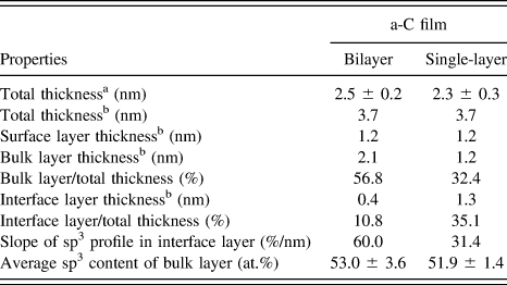
a TEM measurement.
b EELS measurement.
The presented TEM and EELS results can be further interpreted in the context of the fundamental mechanisms of a-C film growth Reference Robertson20 and the subplantation theory. Reference Lifshitz, Kasi, Rabalais and Eckstein21 When the energy of incident C+ ions exceeds a penetration threshold, the ions invade the target material and occupy interstitial sites. The increase of the local density by quenching incident atoms promotes the transition to a denser metastable phase, which enhances sp3 hybridization. For an ion energy above the penetration threshold, a small fraction of the energy is used by the ions to penetrate the surface, about 30% of the energy is consumed by atom displacements, and the rest is dissipated in the form of collision, thermalisation, and relaxation processes, with the last two processes promoting the decrease of sp3 bonding. Reference Robertson20 These competing processes explain the existence of an optimum ion energy of ∼100 eV (i.e., −100 V substrate bias voltage) for synthesizing a-C films with the highest sp3 content.
Another important finding of this study is the effectiveness of the buffer film to hinder subplantation in the NiTa underlayer, which is critical for applications where the substrate properties must be preserved (e.g., magnetic media of hard disks). As shown in Figs. 2(a) and 2(b), film deposition under optimum FCVA conditions affected only the upper part of the buffer film, where the originally low sp3 content increased significantly. This suggests that subplantation was confined to the upper part of the buffer film and the subsequently deposited a-C film, as indicated by the increase of the sp3 content [Fig. 2(b)]. This could be attributed to the appreciable sp3 content (∼49%) of the original buffer film, which contributed to its resistance against subplantation under the present FCVA conditions. Hence, a substrate bias voltage of −100 V produced a-C films with the highest sp3 content without affecting the structure and composition of the NiTa underlayer, because subplantation was confined in the buffer film and the bulk layer of the a-C film. Furthermore, the smooth integration of the buffer film with the a-C film [Fig. 2(b)] indicates that the a-C film is well bonded to the NiTa/glass substrate.
In this investigation, an initial process step of low-ion-energy deposition and a final process step of Ar+ ion sputter etching were integrated with FCVA film deposition (under optimum conditions of pulsed substrate biasing) to synthesize ultrathin bilayer a-C films with structures dominated by the sp3-rich bulk layer. The thickness and cross-sectional structure of hydrogen-free ultrathin a-C films were examined in detail by HRTEM and EELS. The results of this study have direct implications in technologies requiring ultrathin protective overcoats, such as ultrahigh-density magnetic recording, optical lenses, micromirrors, and bioinstruments.
IV. CONCLUSIONS
The thickness, structure, and composition of single-layer and bilayer a-C films synthesized by a multistep FCVA deposition method were characterized by cross-sectional HRTEM and EELS. By depositing first an ultrathin (∼1 nm) carbon buffer film without applying a bias voltage, the interface layer thickness of FCVA a-C films, subsequently deposited under optimum substrate biasing conditions, was reduced by ∼69%, which is critical to preserving the substrate properties and composition, while the thickness of the sp3-rich bulk layer was increased by 75%, which is essential for the protective capacity of the a-C film. In addition, the sp3 content of the bulk layer of bilayer a-C films was slightly increased. The obtained HRTEM and EELS results indicate that the bilayer film deposition method developed in this study can effectively reduce the overcoat film thickness, while preserving or even improving the overall film quality. The principal contribution of the present investigation is the modification of a fairly new film deposition method (FCVA), which enables the deposition of bilayer ultrathin (<4 nm) a-C films with structure and properties dominated by those of the stronger (sp3-rich) bulk layer. The representative HRTEM and EELS results of this study illustrate the high potential of the present multistep FCVA deposition method to produce a-C films with unique structure and properties for a wide range of technologies requiring surface protection by ultrathin overcoats.
ACKNOWLEDGMENTS
The TEM and EELS studies were carried out at the National Center for Electron Microscopy, Molecular Foundry, Lawrence Berkeley National Laboratory (Proposal No. 1886). The work at the Molecular Foundry was supported by the Office of Science, Office of Basic Energy Sciences, U.S. Department of Energy (Contract No. DE-AC02-05CH11231).