I. INTRODUCTION
The enormous requirement for hydrogen peroxide (H2O2) is currently one of the most important issues in the world. In recent years, an attractive route for producing H2O2 is by means of the electrochemical process in fuel cell setup: oxygen reduction reaction (ORR) with a 2-electron pathway.Reference Wood, O’Hayre and Pylypenko1–Reference Yamanaka and Murayama3 In past decades, ORR has been an intense research in the emerging fuel cell technology.Reference Yang and Chang4–Reference Dignard-Bailey, Trudeau, Joly, Schulz, Lalande, Guay and Dodelet6 And noble metals (such as Pt) based materials are the most efficient catalysts, while high cost and scarcity have limited their practical applications. Therefore, the development of non-noble metal-based materials is still the research focus.
In recent years, a series of considerable researches for non-noble metal based catalysts with comparable activity have been found, including graphene,Reference Liang, Li, Chen, Cui, Han, Peng and Liu7 carbon nanotube,Reference Zhong, Luo, He, Tang, Li, Alonso-Vante and Feng8 phthalocyaninesReference Yan, Xu, Liu, Guo, Kang and Yao9 and porphyrin.Reference Oldacre, Friedman and Cook10 Among them, MN4-centers of transition metal N4-macrocycles (MN4) such as metal (Fe, Co) porphyrins (P) and phthalocyanines (Pc) were firstly reported as novel ORR catalysts in alkaline or acidic media,Reference Jasinski11 and then their utilization as ORR catalysts has led to enormous researches.Reference Wang, Wang, Zhong, Zhao, Han, Huang, Zeng, Fan and Li12–Reference Pan, Ma, Zhang, Liu, Zhang, Li, Yang, Zhang and Tong14 Compared to Pt, the pryrolyzed N4-metal macrocycles exhibited the better ORR ability in neutral condition.Reference HaoYu, Cheng, Scott and Logan15 Early on, some technologies such as vacuum sublimation and vapor deposition were used to immobilize them on the surfaces of working electrodes.Reference Zagal, Griveau, Silva, Nyokong and Bedioui16,Reference Putten, Elzing, Visscher and Barendrecht17 However, on account of their poor electric conductivity, these catalysts exhibited weak electrochemical activities.Reference Putten, Elzing, Visscher and Barendrecht17 Hence, it is necessary to provide conductive supports to enhance catalytic abilities of these catalysts. Generally, the common method is to utilize carbon supports due to their large specific surface areas such as rGO,Reference Tang, Yin, Wang, Yang, Wang and Tang18 black pearlReference Sonkar, Prakash, Yadav, Ganesan, Sankar, Gupta and Yadav19 and carbon black.Reference Li, Song, Zhang, Liu, Wang, Sun and Guo20 The MP and MPc complexes can be easily adsorbed on carbon supports through non-covalent π–π intercalations, resulting in promoted electron transfer ability and stabilized systems.Reference Morozan, Campidelli, Filoramo, Jousselme and Palacin21 As metalloporphyrins were sensitive to pH or temperature, and unstable in organic media, building of inorganic matrix can be another way to overcome the above problems and enhance conductivity simultaneously. Besides, the inorganic–organic nanocomposite with layered structures can open up the possibility of “design-and built” two-dimension layered structured material for practical applications.
Layered metal oxide semiconductor (LMOS) is a class of compounds composed of negatively charged metallic oxide layers and charge-balancing cations within the interlayer galleries.Reference Wang, Fan, Yi, Xu, Zhang and Tong22,Reference Pan, Xu, Zhang, Li, Wang, Ma, Liu, Zhang and Tong23 Recently, LMOS materials have attracted wide attentions in fields of optics, electrochemistry and catalysts owing to their unique structure and properties.Reference Pearson24–Reference Liu, Hou and Qu27 Although LMOSs showed the poor electro-conductivity, some surprising photoelectric activities can be found via intercalating functional guest molecules, such as methyl viologen,Reference Zhang, Li, Liu, Feng, Zhang, Tong and Inoue28 Ru(bpy)3,Reference Tong, Takagi, Tachibana, Takagi and Inoue29 and C3F7-Azo+.Reference Tong, Takagi, Shimada, Tachibana and Inoue30 Besides, with the development of nanosheets, it was found that LMOS can be exfoliated into monolayer or few-layer 2D nanosheets with large surface areas and then used as building blocks to form ordered layered nanocomposites via layer-by-layer assembly, namely the self-assembling route.Reference Wang, Fan, Yi, Xu, Zhang and Tong22,Reference Pan, Xu, Zhang, Li, Wang, Ma, Liu, Zhang and Tong23,Reference Liu, Han, Ji, Sun, Zhao, Chen, Chen, Guo, Hou and Ding31,Reference Zhai, Yang, Xu, Hu, Zhang, Hou and Fan32 Among the reported LMOSs, LiNbMoO6, as a typical layered material, has been well studied in view of its good ion-exchange and swelling properties.Reference He, Li, Tang, Yang, Li, Li and Li33,Reference Shen, Zhang, Liu, Xin, Fei, Luo, Ma and Zhang34 Hence, it is feasible to intercalate porphyrin into [NbMoO6]− NSs to form ordered layered nanocomposites with improved catalytic ability and stability.
In this work, a comprehensive physical and electrochemical study of the CoTMPyP/[NbMoO6]− NSs ORR catalyst was prepared via a simple self-assembling method. The resulted samples were characterized by means of X-ray diffraction (XRD), SEM, HRTEM, FT-IR and UV-vis, as well as the investigations of electrocatalytic activities towards ORR. The results demonstrated that the CoTMPyP/[NbMoO6]− NSs naocomposite exhibited excellent catalytic abilities towards ORR in neutral solution.
II. EXPERIMENTAL
A. Preparation of CoTMPyP/[NbMoO6]− NSs/GCE
The LiNbMoO6 was synthesized by calcinating the mixture of Li2CO3, Nb2O5 and MoO3 with a stoichiometric molar ratio of 1:1:2 at 580 °C for 24 h with one intermediate grinding.Reference Bhuvanesh and Gopalakrishnan35 The proton exchange reaction of LiNbMoO6 was carried out in HNO3 solution (2 mol/L) for three days at ambient temperature with the refreshed acid solution every day. The resulted HNbMoO6 was obtained by drying at 50 °C for 24 h in a vacuum drying oven. 0.05 g of as-prepared HNbMoO6 and 455 μL of tetrabutylammonium hydroxide (TBAOH, 10 wt%) aqueous solution were added into 23 mL of deionized water under continuous stirring for four days. The [NbMoO6]− NSs were obtained by centrifugation at 1500 rpm for three minutes.
The CoTMPyP was synthesized by refluxing H2TMPyP (0.10 g) and CoCl2·6H2O (0.09 g) in 10 mL 10−3 mol/L HCl solution at 103 °C for 24 h under nitrogen atmosphere. After reaction, the product was characterized by UV-vis analysis. Once the typical absorption peaks of CoTMPyP appeared, indicating the incorporation of cobalt in the porphyrin. Then the mixture was treated by 100 μL of saturated NaClO4 solution and then stood for one day. The resulted suspension was centrifuged at 8000 rpm and fully washed with 0.1 mol/L NaClO4 solution for several times.Reference Hambright and Fleischer36 The precipitate was dried at 50 °C in vacuum.
To prepare CoTMPyP/[NbMoO6]− NSs nanocomposite, 1 mmol/L CoTMPyP aqueous solution was dropwise added into the [NbMoO6]− NSs with an appropriate volume ratio (CoTMPyP:[NbMoO6]− NSs = 1:1), and abundant brown precipitates appeared immediately. After persistent stirring for one hour, the precipitate was separated from the liquid through centrifugation. Finally, the CoTMPyP/[NbMoO6]− NSs nanocomposite were obtained after water washing and vacuum drying. 2.0 mg of the CoTMPyP/[NbMoO6]− NSs were dispersed in 1.0 mL deionized water for electrochemical tests after sonication. The modified electrode of CoTMPyP/[NbMoO6]− NSs/GCE was prepared by simple doping method, in which 8.0 μL of CoTMPyP/[NbMoO6]− NSs aqueous solution was coated on the glass carbon electrode (GCE) and form a uniform film with an area loading of 0.18 mg/cm2.
B. Characterization
Scanning electron microscope (SEM) images were taken on a FEI Nova NanoSEM 450 instrument (FEI, Hillsboro, Oregon). Transmission electron microscope (TEM), scanning transmission electron microscopy (STEM) and elemental mapping images were obtained from a JEOL JEM-2100F TEM (JEOL Ltd., Tokyo, Japan) operating at an acceleration voltage of 200 kV. XRD measurements were carried out on a RINT 2000 diffractometer (Rigaku Corporation, Tokyo, Japan) using Cu Kα radiation (λ = 0.154 nm) with 2θ ranging from 1.5° to 70° at a scan rate of 1°/min. Atomic force microscope (AFM) analysis was measured on a Bruker Dimension Edge SPM AFM. Zeta potentials of nanosheets were performed on a Malvern Zetasizer Nano analyzer (Malvern Instruments Ltd., Malvern, UK). Fourier transform infrared (FTIR) spectra were performed using a Shimadzu FTIR-8400S apparatus spectrometer (Shimadzu Corp., Tokyo, Japan) with the use of the KBr pellets. UV-vis absorption spectra were recorded using a UV-vis spectrometer (UV-2550). The three-electrode electrochemical cell was used in electrochemical impedance spectroscopy (EIS), cyclic voltammetry (CV) and liner sweep voltammetry (LSV) measurements, with a saturated calomel electrode (SCE) as the reference electrode, a platinum wire as the counter electrode and a GCE coated by CoTMPyP/[NbMoO6]− NSs hybrid film as the working electrode. CV was tested at CHI660E electrochemical workstation, and LSV analysis was carried out using a glassy carbon rotating disc electrode (RDE, Pine Research Instrumentation, Hong Kong, China), connected to an Autolab potentiostat/galvanostat (PGSTAT-302N) work station. Both CV and LSV measurements were proceed in 0.2 mol/L phosphate buffer solution (PBS) system.
III. RESULTS AND DISCUSSION
A. Materials characteristics
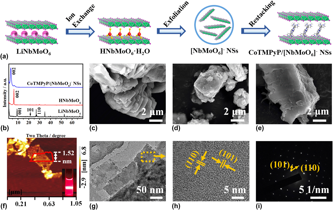
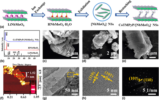
Figure 1(a) shows the schematic illustration for the synthesis of CoTMPyP/[NbMoO6]− NSs composite. Firstly, the pure LiNbMoO6 was prepared through sintering process. The XRD pattern of LiNbMoO6 with interlayer distance value of 0.96 nm was in line with JCPDS Card (No. 50-0884), indicating the high crystalline nature [Fig. 1(b)]. As shown in Fig. 1(c), SEM image of LiNbMoO6 shows a typical layered structure with smooth surfaces and tight packing. Secondly, pure LiNbMoO6 was treated with HNO3 for ion-exchanging with the increased d-spacing of 1.39 nm [Fig. 1(b)], suggesting that the interlayered Li+ was exchanged with H3O+. The protonated HNbMoO6 also retained the layered structure with a little disorder and rough surface [Fig. 1(d)]. Thirdly, HNbMoO6 was fully exfoliated into [NbMoO6]− NSs in TBAOH aqueous solution, which can be determined by AFM with the thickness of approximately 1.52 nm [Fig. 1(f)]. As the crystallographic thickness of [NbMoO6]− layer is 0.806 nm,Reference He, Li, Tang, Yang, Li, Li and Li33 the enhanced thickness value may be due to the presence of the absorbed water molecules.Reference Shen, Zhang, Liu, Xin, Fei, Luo, Ma and Zhang34 When the colloid solution was irradiated with a laser beam, a clear Tyndall effect could be observed, demonstrating the formation of the stable [NbMoO6]− NSs [Inset image of Fig. 1(f)]. Fourthly, [NbMoO6]− NSs was combined with CoTMPyP aqueous solution to form CoTMPyP/[NbMoO6]− NSs hybrid via self-assembling method. Compared with HNbMoO6, the interlayer spacing was increased from 1.39 to 2.47 nm [Fig. 1(b)]. By subtracting the thickness of [NbMoO6]− layer (0.806 nm), the net interlayer height of CoTMPyP/[NbMoO6]− NSs can be calculated as 1.67 nm. Considering the length of CoTMPyP molecule to be 1.8 nm estimated by MM2 calculation,Reference Pan, Xu, Zhang, Li, Wang, Ma, Liu, Zhang and Tong23 the CoTMPyP molecules might be arranged as a sandwiched structure between [NbMoO6]− layers with a tilted angle of 68°. As displayed in Figs. 1(e) and 1(g), SEM and TEM images of CoTMPyP/[NbMoO6]− NSs maintain the layered structure with the increased rough surface due to the introduction of CoTMPyP molecules. From HRTEM image of CoTMPyP/[NbMoO6]− NSs, the clear lattice fringes value of 0.407 and 0.326 nm can be observed, which is attributed to the (101) and (110) plane of LiNbMoO6, respectively [Fig. 1(h)], which is further confirmed by selected area electron diffraction (SAED) pattern. Figure 1(i) displays the typical (101) and (110) lattice planes of LiNbMoO6. The results are in agreement with XRD data, suggesting that there is no phase segregation between CoTMPyP molecules and [NbMoO6]− NSs during the self-assembling process.Reference Wang, Zhou, Wang, Lai and Han37
(a) Schematic illustration of the self-assembly process of CoTMPyP/[NbMoO6]− NSs. (b) XRD patterns of samples. SEM images of LiNbMoO6 (c), HNbMoO6 (d) and CoTMPyP/[NbMoO6]− NSs (e). (f) AFM image and representative height profiles of [NbMoO6]− NSs (inset image is the photograph of [NbMoO6]− NSs in TBAOH aqueous solution). TEM (g), HRTEM (h), and SAED (i) pattern of CoTMPyP/[NbMoO6]− NSs.

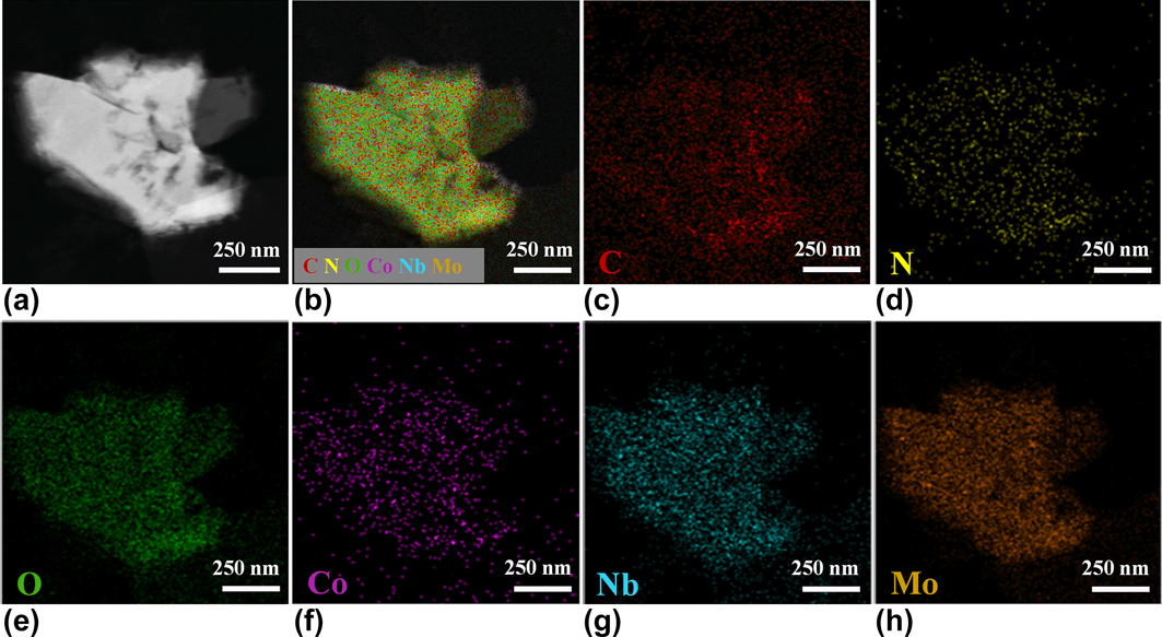
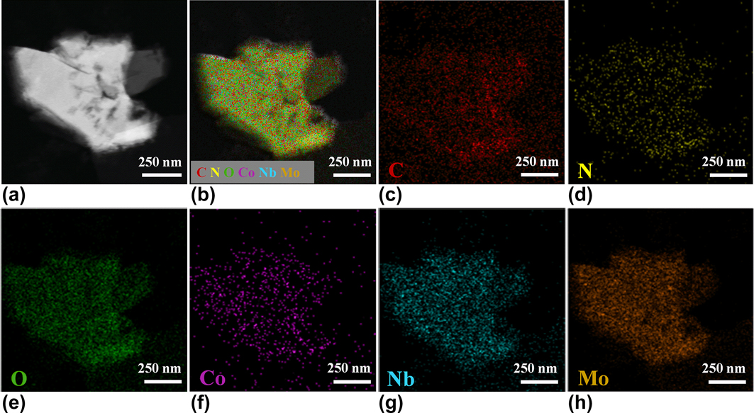
The presence of CoTMPyP in CoTMPyP/[NbMoO6]− NSs composite was confirmed by elemental mapping. As shown in Figs. 2(b)–2(h), the distribution of all constituent elements, including C, N, O, Co, Nb, and Mo, has a high spatial correlation, which is consistent with the physical position of CoTMPyP/[NbMoO6]− NSs.
(a) STEM DF image and (b)–(h) corresponding elemental mapping images of CoTMPyP/[NbMoO6]− NSs.
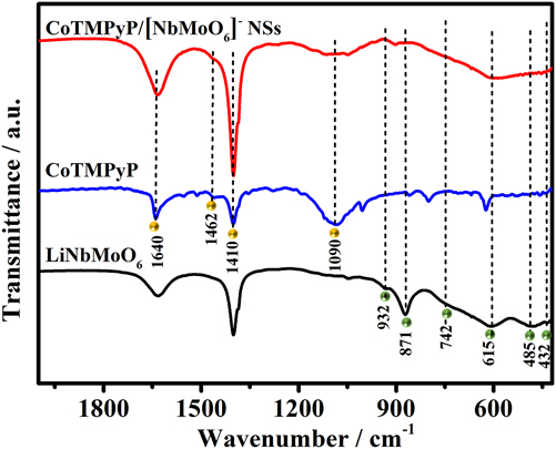
FT-IR and UV-vis analysis were further carried out to prove the fabrication of CoTMPyP/[NbMoO6]− NSs. In Fig. 3, the peaks at 932, 871, 745, 615, 485, and 432 cm−1 in the LiNbMoO6 are ascribed to vibrations of versus (Mo=O), versus (Nb=O), versus (Mo–O–Nb), versus (O–Mo–O), versus (O–Nb–O), and versus (O–Nb–O), respectively.Reference He, Li, Tang, Yang, Li, Li and Li33 For CoTMPyP, the peaks at 1640, 1462, 1410, and 1090 cm−1 are assigned to v (C=N) in the pyridine substituent group, v (C=N), v (C=C), and v (C–N) in porphyrin rings, respectively.Reference Liu, Ma, Shao, Zhang, Gong and Tong38 After combining CoTMPyP with [NbMoO6]− NSs, CoTMPyP/[NbMoO6]− NSs shows a slight shift of characteristic peaks in comparison with CoTMPyP and LiNbMoO6 NSs, which is mainly due to the presence of the strong interaction between two components.Reference Pan, Xu, Zhang, Li, Wang, Ma, Liu, Zhang and Tong23
FT-IR spectra of samples.

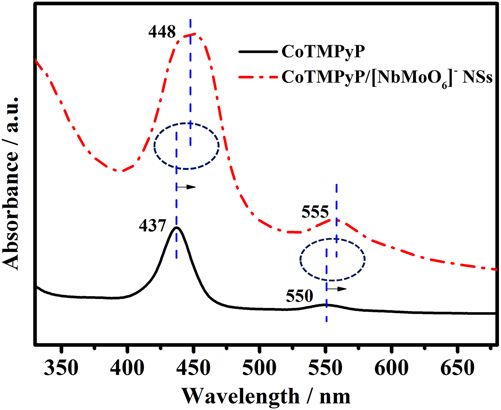
As shown in Fig. 4, CoTMPyP shows the Soret band (437 nm) and Q band (550 nm), respectively. After combination with [NbMoO6]− NSs, the red shifts in Soret and Q bands can be observed for CoTMPyP/[NbMoO6]− NSs with the enhanced absorption intensity, which further confirms the presence of interaction between two components. Based on the above results, it indicates that the CoTMPyP molecules are successfully intercalated into [NbMoO6]− NSs layers instead of simple physical adsorption.
UV-vis absorption spectra of samples.

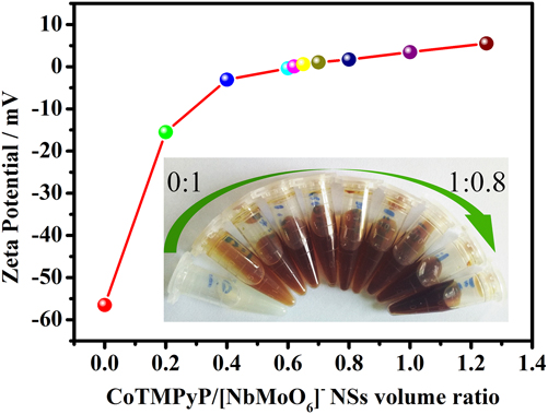
The zeta potential is the external surface potential that is connected with surface charge. As shown in Fig. 5, pure [NbMoO6]− NSs shows a pale yellow colloid solution with a zeta potential value of −56.5 mV. When CoTMPyP aqueous solution was added into [NbMoO6]− NSs, the potential value was gradually increased with the appearance of large amounts of dark brown precipitates. When the volume ratio of CoTMPyP and [NbMoO6]− NSs was 0.62:1, the potential value reached about zero, indicating the most unstable condition. The results indicate the electrostatic action is the main driving force in this strategy.
The relationship between zeta potential and CoTMPyP/[NbMoO6]− NSs volum ratio (inset is the photograph of CoTMPyP/[NbMoO6]− NSs composite with different proportion).

B. Electrochemical activity
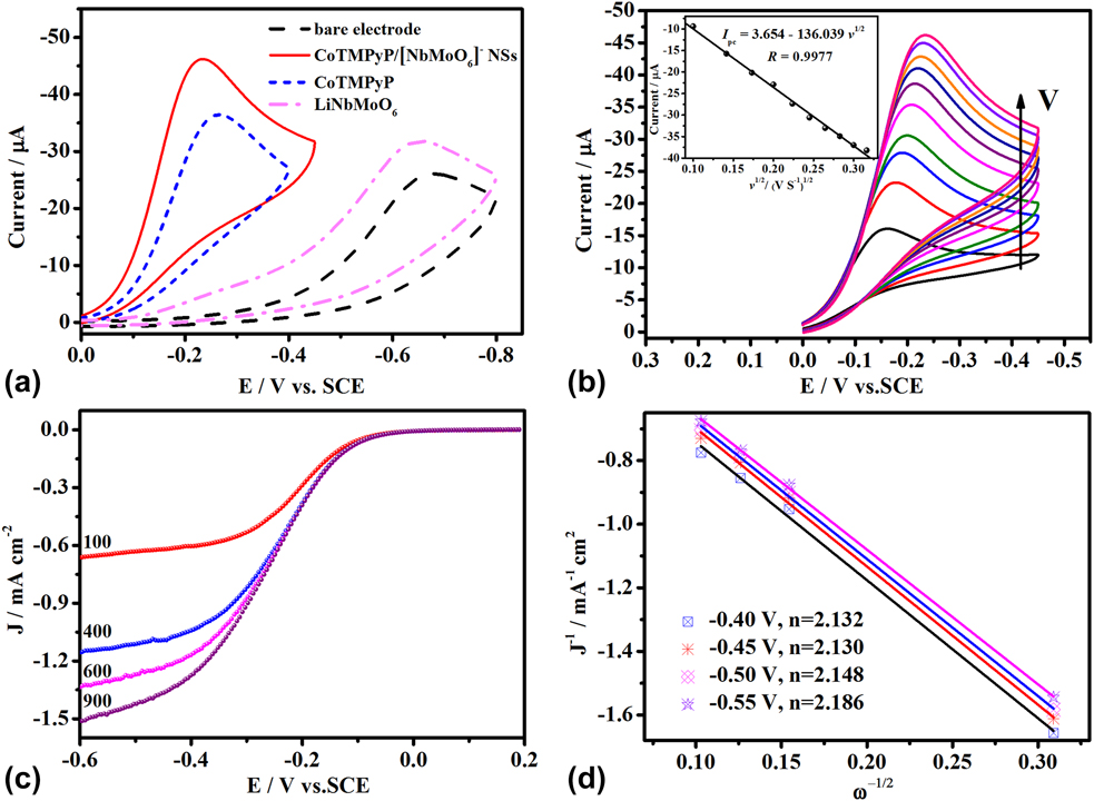
The CV performances of the ORR on bare electrode, CoTMPyP/[NbMoO6]− NSs, CoTMPyP and LiNbMoO6 modified electrodes were measured in O2-saturated 0.2 mol/L PBS (pH 7.0) with a scan rate of 100 mV/s [Fig. 6(a)]. Obviously, it can be seen that the reduction peak potential (E pc) of the modified electrodes shift towards positive than bare GCE, indicating the catalytic reduction of oxygen. However, for LiNbMoO6/GCE, the peak current is weak owing to the semiconductive property.Reference Zhang, Wang, Li, Liu, Ma, Gong, Yang, Xu and Tong39 The E pc of CoTMPyP/[NbMoO6]− NSs/GCE (−0.235 V) is higher than that of bare electrode (−0.681 V) and CoTMPyP (−0.268 V) modified electrodes, besides, the reduction peak current (I pc) increases from 26.07 to 46.20 μA. The results indicate that the CoTMPyP/[NbMoO6]− NSs composite with excellent charge transporting ability shows an enhanced electrocatalytic activity towards ORR. In addition, the slopes of 236.1, 123.4, and 113.6 mV/dec are obtained for Tafel plots of CVs recorded on LiNbMoO6/GCE, CoTMPyP, and CoTMPyP/[NbMoO6]− NSs/GCE, respectively, suggesting that the modification of the GCE with CoTMPyP/[NbMoO6]− NSs observably accelerated the kinetic of the reaction. And the rate determining step for the reaction on the surface of modified electrode is the first charge transfer step. The enhanced activity is mainly due to the synergetic effects of CoTMPyP and [NbMoO6]− NSs, which provides more electron channels for electrochemical reactions. Moreover, the reduction peak currents are proportional to the square root of scan rates from 10 to 100 mV/s [Fig. 6(b)], suggesting that the ORR on the CoTMPyP/[NbMoO6]− NSs/GCE is a typical irreversible diffusion-controlled electrochemical process. For an irreversible reaction, the peak current (I p) can be represented by the following equationsReference Fuerte, Corma, Iglesias, Morales and Sánchez40,Reference Zuo, Yuan, Yang, Zuo and Lu41 :
 $${I_{\rm{p}}} = 0.4958nFA{C_0}{\left( {{{\alpha {n_\alpha }F} \over {RT}}} \right)^{1/2}}{\nu ^{1/2}}{D_0}^{1/2}\quad ,$$
 $$\Delta {E_{\rm{p}}} = {{1.15RT} \over {\alpha {n_\alpha }F}}\quad ,$$
Where n is the number of transferred electrons, A is the surface area of CoTMPyP/[NbMoO6]− NSs modified electrode (A = 0.030 cm2), C 0 and D 0 are the bulk concentration (C 0 = 1.2 mmol/L) and the oxygen diffusion coefficient (D 0 = 1.7 × 10⁻⁵ cm2/s), respectively. α is the transfer coefficient, and n α is the number of electron transferred in the rate-determining step. ΔE p is the peak separation when the scan rates are increased from 10 to 100 mV/s. R, T, and F are gas constant, temperature and Faraday constant, respectively. Based on the slope of I p versus ν1/2 plot, the value of electrons transferred toward oxygen molecules reaction can be calculated to be 1.6 ≈ 2, indicating that the two-electron transfer is the rate-determining step in the overall ORR of the process.
(a) CVs of bare electrode (dash line), CoTMPyP/[NbMoO6]− NSs/GCE (solid line), CoTMPyP/GCE (short dash line) and LiNbMoO6/GCE (dash dot line) in O2-saturated 0.2 mol/L PBS (pH 7.0) at a scan rate of 100 mV/s. (b) CVs of CoTMPyP/[NbMoO6]− NSs/GCE in O2-saturated 0.2 mol/L PBS (pH 7.0) at different scan rates, v (from inner to outer):10, 20, 30, 40, 50, 60, 70, 80, 90, 100 mV/s. Inset: the relationship between v 1/2 and I pc. (c) LSVs for CoTMPyP/[NbMoO6]− NSs/GCE in O2-saturated 0.2 mol/L PBS (pH 7.0) at different rotation speeds. (d) Koutecky–Levich plots according to (c) at different electrode potentials.

In addition, the transferred electron number was further studied through rotating-disk electrode (RDE) measurements according to the following Koutecky–Levich equationsReference Huang, Zhong, Li, Tang and Feng42,Reference Yin, Tang, Wang, Gao and Tang43 :
 $${1 \over J} = {1 \over {{J_{\rm{d}}}}} + {1 \over {{J_{\rm{K}}}}} = {1 \over {B{\omega ^{{1 \over 2}}}}} + {1 \over {{J_{\rm{K}}}}}\quad ,$$
 $$B = 0.62nF{C_0}D_0^{{2 / 3}}{v^{{{ - 1} / 6}}}\quad ,$$
 $${J_{\rm{K}}} = nFk{C_0}\quad ,$$
Where J is the current density, J d is the diffusion limited and J k is the kinetic current density. ω, v, and k represent the angular velocity, the kinetic viscosity and the electron transfer rate constant, respectively. n is the number of electrons transferred. F is the Faraday’s constant. C 0 and D 0 represent the concentration of dissolved oxygen and the diffusion coefficient of oxygen, respectively. Figure 6(c) presents the LSVs of CoTMPyP/[NbMoO6]− NSs/GCE at different rotating speeds. The calculation standard on current density is electrode area. As expected, the limiting current densities increase clearly with the rotation rate. The fitting lines of the Koutecky–Levich plots at different potentials are listed in Fig. 6(d). It indicates that the ORR belongs to the first-order kinetics. The number of electrons transferred is calculated to be 2.1 ≈ 2, which is in line with the results of CVs. Therefore, the electrocatalytic reduction of oxygen on the CoTMPyP/[NbMoO6]− NSs modified electrode is a two-electron-dominated process with the final product of H2O2. Based on the above results and literaturesReference Liu, Zhang, Zhang, Ghosh, Jung, Downing and Whittemore44,Reference Durand and Anson45 the catalytic mechanism may be proposed as follows:
 $${\rm{C}}{{\rm{o}}^{{\rm{III}}}}{\rm{TMPyP}} - {\rm{O}}{{\rm{H}}^ - } \!+ {{\rm{H}}^ + } \!+ {{\rm{e}}^ - } \Leftrightarrow {\rm{C}}{{\rm{o}}^{{\rm{II}}}}{\rm{TMPyP \,+\, }}{{\rm{H}}_{\rm{2}}}{\rm{O}}\quad ,$$
 $${\rm{C}}{{\rm{o}}^{{\rm{II}}}}{\rm{TMPyP \,+\, }}{{\rm{O}}_{\rm{2}}} \Leftrightarrow {\rm{C}}{{\rm{o}}^{{\rm{II}}}}{\rm{TMPyP}} - {{\rm{O}}_2}\quad ,$$
 $${\rm{C}}{{\rm{o}}^{{\rm{II}}}}{\rm{TMPyP}} - {{\rm{O}}_2} + {{\rm{H}}_2}{\rm{O}} + 2{{\rm{e}}^ - } \Leftrightarrow {\rm{C}}{{\rm{o}}^{{\rm{II}}}}{\rm{TMPyP}} - {\rm{O}}{{\rm{H}}^ - } + {\rm{HO}}_2^ - \quad ,$$
IV. CONCLUSIONS
In summary, we prepared the [NbMoO6]− NSs-supported non-noble metal CoTMPyP catalyst through a simple self-assembling method. Delaminated [NbMoO6]− NSs carried negative charges and were readily flocculated with positively charges CoTMPyP solution. This method made it possible for their fast collection and transfer and for subsequent electrochemical applications. The resulted samples were composed of sandwich-like layered structure with CoTMPyP molecules lying between [NbMoO6]− NSs with a tilted angle of 68°, as corroborated by XRD, SEM, HRTEM, FTIR, and UV-vis studies. The CoTMPyP/[NbMoO6]− NSs nanocomposite exhibited excellent catalytic abilities towards ORR in neutral solution. CVs indicated that the composite could promote electron transfer. Both CV and LSV results demonstrated that O2 could be reduced to generate H2O2 through a 2-electron process. In consideration of the vast structural diversity of metal porphyrin macrocycles, it can be believed that this type of LMOS nanosheets catalyst will not limit in the application in oxygen electrocatalysis, and is worth of long-term attention.
ACKNOWLEDGMENTS
This work was supported by Natural Science Fund of Jiangsu Province (BK20161294), HHIT Research Project (Z2015011), Lianyungang Science Project (CG1602) and University Science Research Project of Jiangsu Province (15KJB430004).