Introduction
Since its first practical demonstration in 1981,[Reference Larrondo and St. John Manley1] the melt electrospinning fabrication technique has been under-utilized as a technique for the production of polymer microfibers due to several factors, principally amongst them the lack of ability to produce nanoscale fibers. In recent years the dimension of features achievable via the melt electrospinning technique has been significantly reduced,[Reference Lyons, Li and Ko2, Reference Brown, Dalton and Hutmacher3] and the lack of solvents used in the fabrication process has enabled the creation of bioscaffolding structures for use in tissue and organ growth.[Reference Wunner, Willie, Noonan, Bas, Dalton, De-Juan-Pardo and Hutmacher4] Additionally, the melt electrospinning technique allows for greater control over feature placement and demonstrates minimal charge accumulation on deposited fibers structures, allowing multiple layers of fibers to be deposited sequentially on top of each other and resulting in the creation of three-dimensional fiber structures.[Reference Brown, Dalton and Hutmacher3] Even with increased use of the melt electrospinning technique to produce fiber mats for filtration and biomedical applications, the critical parameter unique to melt electrospinning, thermal energy, is still under-utilized. In the creation of polymer melts, a great deal of thermal energy is expended and utilized solely in melting the polymer; thermal energy transferred to and removed from the polymer melt during melt electrospinning could be utilized to drive chemical reactions in the polymer melt prior to extrusion into the high strength electric field. A solid-state reaction of particular interest is the reaction between lead halides (PbX2) and methylammonium halides (CH3NH3X) resulting in the synthesis of hybrid perovskites. Hybrid perovskites are of interest as they are an easily synthesized material with desirable optoelectronic properties including high optical absorbance,[Reference Zhang, Lanty, Lauret, Deleporte, Audebert and Galmiche5–Reference Ziang, Shifeng, Laixiang, Shuping, Wei, Yu, Li, Zhijian, Shufeng, Honglin, Minghui and Qin7] strong photoluminesce,[Reference Tan, Moghaddam, Lai, Docampo, Higler, Deschler, Prince, Sadhanala, Pazos, Credgington, Hanusch, Bien, Snaith and Friend8, Reference Bai, Yuan and Gao9] and a high degree of optical tunability.[Reference Noh, Im, Heo, Mandal and Il Seok10] Hybrid perovskites suffer from chemical instability and degrade rapidly in the presence of moisture.[Reference Niu, Guo and Wang11–Reference Yang, Siempelkamp, Liu and Kelly13] Murphy et al. discovered hybrid perovskites can be stabilized through compounding with hydrophobic polymers.[Reference Murphy, Andriolo, Ross, Wyss, Zander and Skinner14] By incorporating hybrid perovskite precursors into the polymer feedstock of a melt electrospinner, the excess thermal energy of the polymer melt can be used to drive the solid-state reaction forming the hybrid perovskite while simultaneously passivating the hybrid perovskite crystallite. The polymer melt also acts as a vehicle for the deposition of hybrid perovskite onto the desired surface. Previous work by Murphy et al. has shown that the melt electrospinning technique is a viable method to produce polymer/perovskite composite microfibers[Reference Murphy, Ross, Andriolo and Skinner15] by thermodynamically driving a solid-state chemical reaction in the polymer melt. In this study the method developed previously will be utilized to fabricate optically active polymer/hybrid perovskite microfibers using both the iodide and bromide hybrid perovskite materials, and the morphology of the hybrid perovskite microcrystallites will be assessed to elucidate the mechanisms at work in the polymer melt.
Experimental section
Materials
Polystyrene (MW 280,000, Sigma-Aldrich) pellets and lead halide (PbI2, 99% & PbBr2, 99%, Sigma-Aldrich) hybrid perovskite precursors were purchased and used as-received from Sigma-Aldrich. Methylammonium iodide and methylammonium bromide were synthesized following similar procedures to J. Qiu et al.[Reference Qiu, Qiu, Yan, Zhong, Mu, Yan and Yang16] in which equimolar amounts of methylamine (33 wt% in absolute ethanol, Sigma-Aldrich) were reacted with the appropriate halodic acid (hydroiodic acid 57 wt% in water, hydrobromic acid 48 wt% in water, Sigma-Aldrich) at 0 °C for 2 h. After 2 h the solvent was removed using a rotary evaporator leaving a methylammonium iodide (CH3NH3I) or methylammonium bromide (CH3NH3Br) white-tan crystalline solid. The white-tan solid was then purified through recrystallization using ethanol and rinsed with diethyl ether prior to drying in a vacuum oven overnight.
Polymer feedstock preparation
Polymer feedstock for the melt electrospinning system was prepared through the mechanical mixing of the neat polystyrene pellets and the hybrid perovskite precursor materials. Hybrid perovskite precursors were loaded into the mixture so the hybrid perovskite would make up 20% of the weight of the composite. The three constituent materials were loaded into a sealable vessel and agitated with a vortex mixer for five minutes to ensure good mixing of the precursors into the polystyrene starting material. Feedstock material was then immediately loaded into the melt chamber to minimize separation of the precursors from the polymer prior to the formation of the melt.
Melt electrospinning conditions
The polymer/perovskite precursor feedstock was loaded into a melt electrospinning apparatus, which consisted of a stainless steel melt chamber with an actuated piston to extrude a polymer melt through a needle into a high strength electric field. The melt electrospinner was then heated to an operating temperature of approximately 260 °C and held at temperature for approximately 10 min to allow the polymer melt to form and begin flowing through the spinneret. A field strength of approximately 3 kV/cm (separation distance 6 cm, applied voltage 20 kV) was necessary to initiate electrospinning of the polymer melt. Polymer fibers were collected on aluminum foil sheets, and glass slides were fixed to a large, grounded steel electrode.
Scanning electron microscopy and energy dispersive spectroscopy
Electron micrographs were collected using a Tescan Mira3 scanning electron microscope operated at 15 kV accelerating voltage. The morphology and distribution of hybrid perovskites/precursor materials in the fibers produced in the melt electrospinning study were assessed using both secondary and backscatter electron characterization. Elemental mapping was collected using an Octane Elect EDS system paired with TEAM software.
X-Ray diffractography
X-Ray diffractography (XRD) was conducted on microfibers ground to powder and loaded into a low-background slide. Analysis was carried out with a Rigaku Ultima IV x-ray diffractometer using a Cu Kα source and a Ni filter at a scan rate of 5°/min from 10° to 70°.
Fluorescence microscopy
Optically active properties of the of composite microfibers were assessed visually using an OMAX epi-fluorescence microscope. Only the bromide hybrid perovskites were analyzed for fluorescence as the iodide hybrid perovskite does not fluoresce in the visible spectrum.
Results and discussion
Melt electrospinning of the composite melt
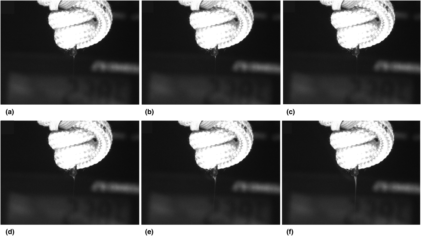
While the melt electrospinning technique was successful in the generation of microfiber mats, the process was hampered by non-continuous electrospinning, which can be seen in Fig. 1.
A time-lapse photo series of the spinneret of the melt electrospinner. An interruption in continuous melt electrospinning can be seen occurring from (a) through (f) over the course of 4 ms. As the particle moves into the Taylor cone, the flow of polymer is restricted around the particle, resulting in an elongation of the cone and the formation of a bead. Nominal width of the spinneret shown is 1.8 mm.

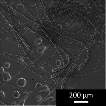
Thermal energy provided by the polymer melt used to drive the hybrid perovskite reaction also results in the agglomeration of the lead halide particles in the polymer melt. When the particles agglomerated into sufficiently large clusters, electrospinning was interrupted, seen in Fig. 1. Agglomerations caused a restriction to the flow of the polymer into the apex of the Taylor cone which decreases the overall cone size after the agglomeration, resulting an increase in the surface area and a decrease in surface charge density of the cone. The change to flow and charge density of the cone interrupts the continuous, stable electrospinning and leads to the creation of a bead, which falls and initiates the electrospinning process again. Several beads formed through this process can be seen in the electron micrograph in Fig. 2.
Secondary electron micrograph of melt electrospun polystyrene microfibers. The formation and dripping of polymer beads results in the formation of a tear-shaped droplet at the terminal end of an electrospun fiber or a polymer spheroid deposited onto the collection electrode.

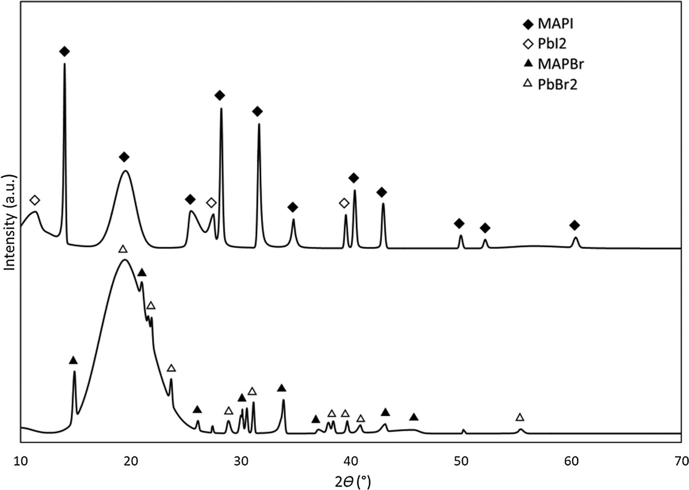
The success of the melt electrospinning technique was directly observable in operando and later verified through optical and electron microscopy, as seen in Figs. 1 and 2, respectively. However, the success of the hybrid perovskite synthesis is not directly observable and must be verified through XRD analysis, Fig. 3. Analysis of the diffractograms in Fig. 3 reveal the presence of the iodide and bromide hybrid perovskites present in the melt electrospun composite microfibers. In addition to hybrid perovskites present in the melt electrospun fibers, residual lead halide precursor material was also observed in the diffractograms.
X-ray diffractogram of pulverized melt electrospun fiber mats of the CH3NH3PbI3 (MAPI, top) and CH3NH3PbBr3 (MAPBr, bottom) hybrid perovskite composite fibers. During the melt electrospinning technique, the methylammonium halide precursor is sublimated. However, residual lead halide precursor remains in the fibers as evidenced above.

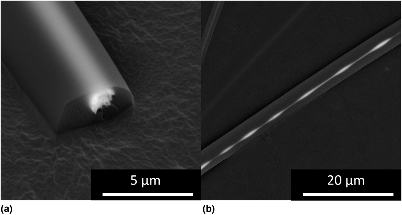
Presence of residual lead halide precursors indicates that not all of the precursors reacted to form hybrid perovskites in the polymer melt. Incomplete use of the hybrid perovskite precursors is due to the sublimation and degradation of the methylammonium halide precursor in the melt chamber at the operational temperature during the melt electrospinning technique. Dualeh et al.[Reference Dualeh, Gao, Il Seok, Nazeeruddin and Grätzel17] determined that methylammonium iodide and methylammonium bromide undergo sublimation at 247 and 195 °C, respectively, in open-crucible conditions. Thermal analysis of the polystyrene, methylammonium iodide, and lead iodide present in the melt electrospinner feedstock was performed individually to assess sublimation in one of the halide hybrid perovskite systems studied. The component that sublimates first, and within the operational temperature range of the melt electrospinner, is the methylammonium iodide. However, the polymer melt effectively limits sublimation of the methylammonium halides by hampering the kinetics of sublimation via the viscous local environment around polymer melt. Furthermore, the loss of sublimated methylammonium halides and their respective degradation products is also slowed by effectively sealing the melt chamber with the polymer melt. An interesting consequence of the sublimation of the methylammonium halide precursor in the melt chamber comes as a result of the degradation of the methylammonium halide gas, creating methylamine gas in the melt chamber. Methylamine gas acts to flux the hybrid perovskite formed in the melt[Reference Zhou, Wang, Zhou, Pang, Wang, Xu, Liu, Padture and Cui18] but has no effect on the precursors or polystyrene melt. Upon removal of the methylamine gas, the hybrid perovskite reverts to its solid state with no deleterious effects. The two-phase liquid consisting of the polymer melt, and the liquified hybrid perovskite can then be electrospun, which draws down the polymer and degases the liquid perovskite to result in microfibers with unique hybrid perovskite filler phase morphologies, as seen in Fig. 4. Hybrid perovskite in the liquid state in the melt electrospinner forms spheres in an attempt to minimize surface energy. In the case of smaller liquid spheres of hybrid perovskite, the methylamine gas is quickly removed, locking in the spherical shape; but when the volume of the liquid hybrid perovskite is sufficiently large, the methylamine gas is not readily removed; and prolate ellipsoids form as a result of either the viscoelastic forces in the fiber in situ or as a result of deformation from the high strength electric field or a combination of both. The final case is when a large sphere of liquid hybrid perovskite is drawn by the surface tension of the polymer melt into the spinneret, resulting in a coaxial-type fiber geometry, seen in Fig. 4.
Backscatter electron micrographs of coaxial polystyrene/hybrid perovskite microfibers. (a) The core of the fiber is encapsulated in polystyrene, effectively passivating it and preventing degradation of the core. (b) Viscoelastic stretching and relaxing of the polymer fiber during electrospinning results in non-uniformities in the hybrid perovskite core material.

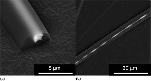
The unique geometry demonstrated in Fig. 4 has been produced using a coaxial-solution electrospinning set-up[Reference Murphy, Andriolo, Sutton, Brockway and Skinner19] but has not yet been demonstrated in a single-needle melt electrospinner. While the microscopic scale hybrid perovskite particle/features provide an understanding of the mechanisms at work in the melt electrospinner, the nanoscale hybrid perovskites are the largest contributor to the optical enhancement of microfibers. A small volume of interaction and obfuscation of nanoscale features by the polymer matrix makes direct visualization of nanoscale hybrid perovskite filler phase difficult. However, the strong optical activity of the nano-hybrid perovskite structures in the polymer matrix enhances photoluminescence of the microfibers under excitation with ultra-violet light. Melt electrospun composite fibers with the bromide perovskite demonstrated strong photoluminesce when interrogated with ultra-violet light. The uniformity of the photoluminesce throughout the micro fibers suggests that MAPBr nanoparticles are well-dispersed throughout the bulk of the polymer matrix in the melt electrospun fibers. With direct-write melt electrospinning it would be possible to fabricate simple and complex fiber-based structures with relative ease.
Conclusions
In this work, a fabrication technique for producing optically active polymer micro/nanocomposite fibers was investigated to elucidate the underlying mechanisms of hybrid perovskite formation in the polymer melt, and the optical activity of composite microfibers produced was assessed. Synthesis of two hybrid perovskites with different halide chemistries was demonstrated and verified through XRD. The formation of hybrid perovskite in the liquid-state in the polymer melt was supported by the unique morphology of hybrid perovskite particles and continuous hybrid perovskite coaxial structures in melt electrospun fibers. Fluorescent microscopy also revealed the presence of nanoscale hybrid perovskite throughout the polymer microfibers, as evidenced by uniform emission from the microfibers under interrogation. The melt electrospinning technique offers the ability to direct-write with polymer melts in multiple layers, allowing the generation of two and three-dimensional structures. When paired with a material with widely tunable optical properties, such as hybrid perovskites, the ability to fabricate light-emitting or transducing structures can be realized. Future work in the creation of optically active polymer/hybrid perovskite composite microfibers should be directed at utilizing liquid hybrid perovskite instead of precursors in the solid-state, which should result in more control of hybrid perovskite loading in polymer fibers. Finally, the incorporation of these fiber structures into pre-existing optical devices, and the fabrication of rudimentary photonic crystals could significantly lower costs associated with production and decrease processing time.
Acknowledgments
Research was sponsored by the Army Research Laboratory and was accomplished under Cooperative Agreement No. W911NF-15-2-0020. The views and conclusions contained in this document are those of the authors and should not be interpreted as representing the official policies, either expressed or implied, of the Army Research Laboratory or the US Government. The US Government is authorized to reproduce and distribute reprints for Government purposes notwithstanding any copyright notation herein.