



1. Introduction
The possibility to control the electrostatic field distribution in plasma has yielded wide prospects for modern technologies. In particular, due to the creation of a radial electric field in mirror traps, it is possible to suppress the magnetohydrodynamic instability and significantly increase the plasma confinement time (Soldatkina et al. Reference Soldatkina, Bagryansky and Solomakhin2008). In tokamaks, the appearance of a radial electric field in the H-mode has made it possible to significantly reduce transverse losses (Jain Reference Jain1993; Burrell Reference Burrell1997), whereas the electric field realized in the Hall thrusters plasma allows for accelerating ions and thereby creates thrust (Boeuf Reference Boeuf2017; Zolotukhin et al. Reference Zolotukhin, Daniels, Brieda and Keidar2020).
As a magnetic field primarily allows for the creation of electric fields in plasma, it serves as an additional obstacle for the current flow through the medium. At the same time, an electric field can be realized along a magnetic field if the mean free path of charged particles is substantially less than the installation size (Jin et al. Reference Jin, Poulos, Van Compernolle and Morales2019).
In the configuration of the magnetic field of a rectilinear solenoid, the creation of a radial electric field in plasma causes rotation of the entire plasma (Barber et al. Reference Barber, Swift and Tozer1972; Del Bosco et al. Reference Del Bosco, Simpson, Dallaqua and Montes1991). This phenomenon led to the fact that in the 1970s–1980s, various schemes of plasma centrifuges for isotope separation were proposed and actively developed (Grossman & Shepp Reference Grossman and Shepp1991). Unlike gas centrifuges, there were no rotating parts in the plasma centrifuges, and it was assumed that the rotation speed could be higher. However, plasma centrifuges have not yet found an industrial application.
In recent decades, methods for plasma processing of spent nuclear fuel (SNF) have been actively developed (Dolgolenko & Muromkin Reference Dolgolenko and Muromkin2017; Zweben et al. Reference Zweben, Gueroult and Fisch2018). In SNF reprocessing (separation of fission products from actinides), a lower resolution of the device is required when compared with the separation of isotopes. Unlike plasma centrifuges, where the elements of the mixture to be separated are in collisional equilibrium, the separation in the new generation of plasma separators is supposed to be carried out in a collisionless mode.
Among the wide variety of separation schemes, there are also those in which the use of crossed electric and magnetic fields in a linear configuration is proposed (Gueroult et al. Reference Gueroult, Zweben, Fisch and Rax2019b; Liziakin et al. Reference Liziakin, Antonov, Usmanov, Melnikov, Timirkhanov, Vorona, Smirnov, Oiler, Kislenko, Gavrikov and Smirnov2021). The simplest scheme of such a separator is shown in figure 1. A cylindrical vacuum chamber is immersed in a longitudinal magnetic field. End electrodes are installed at the ends of the chamber. The voltages on the electrodes are provided by a power supply. At both ends, the distribution of the electrode potential is identical.
Basic diagram of a separator.

In such separators, the possibility to control the radial profile of the potential is actually the possibility to control the particle trajectories (Smirnov et al. Reference Smirnov, Gavrikov, Sidorov, Tarakanov, Timirkhanov, Kuzmichev, Usmanov and Vorona2018, Reference Smirnov, Egorov, Kislenko, Antonov, Smirnov and Gavrikov2020). Therefore, the question about the shape of the profile and the possibility of its adjustment for more efficient separation of the mixture has become particularly topical.
It is necessary to distinguish between cases when the negative potential (Liziakin et al. Reference Liziakin, Gavrikov, Usmanov, Timirkhanov and Smirnov2017) (relative to the outer cylindrical surface) and the positive one (Shinohara & Horii Reference Shinohara and Horii2007) are maintained on the cylinder axis. The difference between these cases consists primarily of the difference between the areas of the negative and positive electrodes. An ion current flows to the negative electrode; its density is much lower than the electron one. For a stationary state, when the total charge of the system is preserved, the magnitude of the current in the system is determined by the area of the electrode collecting ions. The area of the end electrodes, as a rule, is much smaller than the area of the outer cylindrical surface. Hence the current between the electrodes, in the case of negatively biased end electrodes, will be significantly less than for the case of positively biased ones. The present study will focus on the case with negatively biased electrodes.
Liziakin et al. (Reference Liziakin, Gavrikov and Smirnov2020) considered the formation mechanism of a negative potential on the axis of a cylindrical plasma column immersed in a magnetic field. The formula was obtained with which it is possible to estimate the plasma column potential. The current paper will deepen the analysis of such a system and consider the shape of the potential profile.
In the present study, it will be assumed that the plasma along the magnetic field is conducting perfectly. This assumption should be clarified. In a number of cases, the longitudinal conductivity can make a significant contribution to the electric potential distribution even in a magnetized plasma. This can happen because the electrode that sets the potential has small geometrical dimensions compared with the interelectrode distance (Gilmore et al. Reference Gilmore, Lynn, Desjardins, Zhang, Watts, Hsu, Betts, Kelly and Schamiloglu2015; Gueroult et al. Reference Gueroult, Evans, Zweben, Fisch and Levinton2016; Jin et al. Reference Jin, Poulos, Van Compernolle and Morales2019). Poulos (Reference Poulos2019) introduced a dimensionless parameter

where a is the radius of the electrode that sets the potential, L is the cylinder length, and ${\sigma _{||}},{\sigma _ \bot }$ are the longitudinal and transverse plasma conductivities, respectively. Gueroult et al. (Reference Gueroult, Rax and Fisch2019a) verified that in the experiments with end electrodes in which ${s^{ - 1}}$
 was much less than one, the potential was reproduced well. On the other hand, in those experiments where this parameter was of the order of one, a significant change in the plasma potential along the column was observed. Therefore, assuming that the plasma along the magnetic field is ideally conducting, one should have in mind that this parameter is much less than one and, as a result, the change in potential along the magnetic field is negligible.
It should be noted that the ideal conductivity of the plasma in the longitudinal direction does not mean that the density of the current between the electrode and the plasma can reach arbitrarily large values. There is a thin near-electrode layer between these objects. In this layer, it is no longer possible to speak of ideal conductivity, and it is precisely that which can serve as a limiter for the longitudinal current density.
Although in many experimental papers, the end electrodes were made of a large number of concentric electrodes (>2), quite often, all electrodes were divided into one or two groups of short-circuited electrodes and the same voltage was applied to each group of electrodes (Amatucci et al. Reference Amatucci, Walker, Ganguli, Antoniades, Duncan, Bowles, Gavrishchaka and Koepke1996; Shinohara & Horii Reference Shinohara and Horii2007). Thus, a group of short-circuited electrodes effectively acted as a single electrode. In this work, we will consider both the cases of such electrode connections and the general case of independent connection of more than two electrodes.
The main objective of the work is to derive the dependence of the plasma potential radial distribution on the end electrodes potential radial distribution.
To verify the proposed model, we conducted an experimental study and compared its results with the predictions of the model.
2. Ohm's law
Let us consider an axially symmetric system in which the magnetic field is directed along the axis (see figure 1). Let concentric electrodes be placed at the ends of such a system, while the interelectrode gap is filled with plasma.
Although the transverse conductivity across the magnetic field can be influenced by a large number of parameters, which include various types of instabilities, we will consider classical conductivity. Thus, this calculation can be considered as a lower estimate.
In the hydrodynamic plasma model, one can obtain the generalized Ohm's law from the momentum balance equations. Neglecting the motion of neutrals in the laboratory coordinate system (Paschmann et al. Reference Paschmann, Haaland and Rudolf2003), one can obtain the radial component of current density

where ${E_r}$ is the radial electric field and $\sigma _P^n$
 is the transverse conductivity in the rest frame of neutrals.
Let us show that in a certain range of parameters, the main contribution to the transverse conductivity is made by collisions of ions with neutrals. In the model of three liquids (ions, electrons and neutral atoms), the transverse conductivity in the rest system of neutrals has the form (Song et al. Reference Song, Gombosi and Ridley2001)

Here, ${\varOmega _i},{\varOmega _e}$ are the Larmor frequencies of rotation of ions and electrons, while ${\nu _{in}},{\nu _{en}},{\nu _{ei}}$
 are the corresponding collision frequencies. In obtaining this equation, the relation $M{\nu _{in}} \gg m{\nu _{en}}$
 was assumed to be correct. As shown in figure 2, it is valid in a wide range of plasma parameters, in particular, for argon in the range of ${T_e} \in [2,35]\;\textrm{eV}$
 , ${T_i} \in [0.01,100]\;\textrm{eV}$
 . When obtaining figure 2, the values of the elastic collisions cross-section of ions with neutrals in the energy range of 4–400 eV were used from the study by Cramer (1959). At lower energies, we used (2.26) from Raizer et al. (Reference Raizer, Kisin and Allen2011), which determines the polarization cross-section. For the elastic collisions cross-section of electrons with neutrals we used the data from Ramsauer (Reference Ramsauer1922).
Relation between $M{\nu _{in}}$ and $m{\nu _{en}}$
 in argon.

As follows from (2.2) the relationship between the magnetization parameters of electrons and ions determines which of the particle species makes the largest contribution to the transverse transport. Figure 3 shows the components $\kappa$ in their dependence on the magnetic field, neutral gas pressure and plasma density for argon. When analysing this graph, it should be considered that the upper and lower horizontal axes can be changed independently, since they are defined by different components of $\kappa$
 . So the lower axis determines the components ${\varOmega _i}/{\nu _{in}}$
 and ${\nu _{en}}/{\varOmega _e}$
 , and the upper one ${\nu _{ei}}/{\varOmega _e}$
 .
Comparison of the contribution of electrons and ions to the transverse conductivity of plasma. The dashed line indicates the excess of ionic conductivity over the electronic one by 10 times in the considered temperature range of electrons and ions.

To the right of the dashed line in figure 3, there is a domain where the ionic conductivity is more than 10 times greater than the electronic one. Most experiments with end electrodes are performed using the parameters from this domain (Gueroult et al. Reference Gueroult, Rax and Fisch2019a; Liziakin et al. Reference Liziakin, Gavrikov and Smirnov2020). Therefore, it will be further assumed that the plasma conductivity across the magnetic field is determined by the transport of ions. However, it is worth remembering that such a consideration is true only for the indicated B/p and B/ne. In this case, the conductivity takes the form

Here ${\sigma _{in}}$ is the elastic collisions cross-section of ions with neutrals.
3. Radial profile of the potential
It was found in the previous section that in the considered parameter range, the main current across the magnetic field was transported by ions.
Consider the relation between the plasma potential and the potential of the end electrodes in the case when the potential of electrodes monotonically increases with r $({U_{e1}} < {U_{e2}})$ . Figure 4 shows an equivalent electrical circuit. The outer cylindrical surface and electrode 3 are grounded, and their potentials are equal to zero $({U_{e3}} = 0)$
 . On the two inner electrodes $({U_{e1}},{U_{e2}})$
 , a negative potential relative to electrode 3 is maintained by the external power source. The symbols ${V_{\textrm{sh1}}},{V_{\textrm{sh2}}}$
 indicate the near-electrode potential drop. We should point out that the discrete current loops schematically indicated in figure 4 are in fact continuous, and the magnitude of the near-electrode potential drop is radially varying.
Equivalent electrical circuit of an axisymmetric system with an axial magnetic field and end electrodes.

The elementary increment of the plasma potential along the radius can be written in the form

where

whereas ${I_r}$ is the total current along the radial coordinate and L is the length of the plasma cylinder. Taking into account the stationarity of the flow of currents and the law of the charge conservation, one can find that the radial current in an arbitrary coordinate r should be equal to the total current of all the electrodes located in the region $\tilde{r} < r$


where j is the density of current to the end electrodes and $\textrm{d}S = 2{\rm \pi}\tilde{r}\,\textrm{d}\tilde{r}$ . Therefore, the plasma potential at an arbitrary point should be equal to

where $\tilde{r},\hat{r}$ are integration variables and ${r_g}$
 is the inner edge of the grounded electrode.
The plasma conductivity under the integral is a function of the ion velocity, which in turn is a function of the radial electric field.
3.1. Strongly negative equipotential end
The simplest case of connecting the end electrodes is by short-circuiting all of the electrodes to each other except for the outermost one (${U_{e1}} = {U_{e2}}$ , while ${U_{e3}} = 0$
 , figure 4). A large negative potential $e{U_e} \gg {T_e}$
 is applied to electrodes 1 and 2. This configuration looks most like a classical reflex discharge (Liziakin et al. Reference Liziakin, Gavrikov, Murzaev, Usmanov and Smirnov2016). In this case, j from (3.4) can be substituted by the density of the ion saturation current (Lieberman & Lichtenberg Reference Lieberman and Lichtenberg2005) ${j_{is}} = 0.52en{(k{T_e})^{0.5}}{M^{ - 0.5}}$
 times the number of ends with electrodes ${N_{\textrm{surf}}}$
 (1 or 2). If one assumes that the neutral density, plasma density, electron temperature and the cross-section of elastic collisions of ions with neutrals do not depend on the radial coordinate, then the potential increment along the radius can be represented in the form

Here, for simplification, ${\sigma _{in}}$ is taken to be constant and is equal to $2.5 \times {10^{ - 15}}\;\textrm{c}{\textrm{m}^2}$
 , whereas the velocity of ions equals ${u_i} = E/B = U^{\prime}/B$
 . Then, performing integration with respect to the variable $\tilde{r}$
 and denoting

one can get

Differentiating both sides of (3.7), expressing $U^{\prime}$ and integrating from the inner edge of the grounded electrode ${r_g}$
 , one can obtain

Here and after, $F(r)$ is an antiderivative of the function. For ${C_1}r \ll 1$
 , one can expand this in a Taylor series to the first non-zero term

Figure 5 demonstrates potential profiles, calculated by (3.9) with $U({r_g}) = 0$ , under fixed magnetic field, electron temperature, length and radius of installation in argon gas. In this example, ${r_g} = 0.25\;\textrm{m}$
 . The ion-saturation current is the maximal current which can flow through a layer (sheath) of a cold negative electrode. Therefore, the presented profiles are an estimate from above for the possible potential values. For the conditions shown in figure 5, the dimensionless parameter s −1 is in the range (2–55) × 10−3.
Potential radial profile in the configuration when all the electrodes (except for the external grounded electrode) are at a large negative potential $e{U_e} \gg {T_e}$ .

3.2. Floating-gap configuration
In the experimental implementation of the electrode geometry described in the previous section, an arc discharge may occur between negative and grounded electrodes across the magnetic field. To avoid this, one can install another electrode between these electrodes with an intermediate voltage or under a floating potential (${I_2} = 0$ in figure 4). Thus, a buffer zone appears that prevents disruption of the discharge. In this case, the plasma potential will be determined by the system of equations

where ${r_e}$ is the outer radius of the negative electrode. Substituting ${j_{is}}$
 into the second equation of system (3.10) and taking into account (3.2), one can get

Then, similar to (3.7), differentiating both sides of (3.11), expressing $U^{\prime}$ and performing integration, one can get

3.3. Thermionic element on the axis of the system
Equation (3.1) shows that an increase in the potential of the plasma volume can be achieved by increasing the radial current. In an experimental implementation, this can be done by using a thermionic cathode.
When electrons are injected into a vacuum, their current is limited by the Child–Langmuir law (Langmuir & Compton Reference Langmuir and Compton1931). When electrons are injected into neutral plasma, the space charge of electrons is compensated by the space charge of ions in the cathode layer. Although the current of thermoelectrons can significantly exceed the ion-saturation current, its magnitude is bounded just the same. At a low-ion-saturation current, a virtual cathode is formed. The critical thermionic current as a function of the potential of the cathode layer was found by Poulos (Reference Poulos2019).
Consider the case when a thermal cathode with a radius ${r_{\textrm{th}}}$ is situated on the axis. Then the potential increment along the radius will be a piecewise-defined function

Denoting

and considering that

one can obtain, similar to the previous sections,

The constants in the expression are chosen so the function is continuous.
3.4. Slightly negative electrodes
In §§3.1–3.3, particular cases of connecting end electrodes to an electrical circuit were considered. The main simplification that allowed obtaining analytical equations for $U(r)$ is that a large negative potential $e{U_e} \gg {T_e}$
 is applied to the negative electrode. In these cases, as seen from (3.9), (3.12) and (3.16), the plasma potential does not depend on the electrode potential. For such a voltage, the electrons from the plasma cannot get onto the negative electrode, and therefore their current can be neglected. In this section, we consider the case when the electrodes are slightly negative biased $(e{U_e} \sim {T_e})$
 . In this case ${I_r}$
 from (3.1) should be written in the form

Since now the potential of the electrode may not differ much from the potential of the plasma $(e{U_e}/{T_e}\sim 1)$ , regions may appear where $U^{\prime}(r) \to 0$
 , in this case, in (2.3) for the collision frequency, the ion thermal velocity ${u_T}$
 should be added

For ${u_T}$ we use room temperature of 300 K.
If the discharge is self-sustained, that is, the plasma is created only by electrodes, then the area occupied by the plasma is bounded by the condition $r < {r_g}$ . If the plasma is maintained by an external ionization source (electron beam (Maggs et al. Reference Maggs, Carter and Taylor2007), radio-frequency (rf) discharge (Litvak et al. Reference Litvak, Agnew, Anderegg, Cluggish, Freeman, Gilleland, Isler, Lee, Miller, Ohkawa, Putvinski, Sevier, Umstadter and Winslow2003; Shinohara & Horii Reference Shinohara and Horii2007; Gilmore et al. Reference Gilmore, Lynn, Desjardins, Zhang, Watts, Hsu, Betts, Kelly and Schamiloglu2015; Gueroult et al. Reference Gueroult, Evans, Zweben, Fisch and Levinton2016; Liziakin et al. Reference Liziakin, Gavrikov, Usmanov, Timirkhanov and Smirnov2017; Vorona et al. Reference Vorona, Gavrikov, Kuzmichev, Liziakin, Melnikov, Murzaev, Smirnov, Timirkhanov and Usmanov2019), microwave plasma source (Amatucci et al. Reference Amatucci, Walker, Ganguli, Antoniades, Duncan, Bowles, Gavrishchaka and Koepke1996)), then the plasma density may not be equal to zero for $r > {r_g}$
 . In this case, when moving away along the radius from the inner edge of the grounded electrode, the plasma potential tends to the value

Then the distribution of the plasma potential is the solution of the equation

Here, integration is carried out from the outer boundary ${r_{ex}}$ of the electrode system. It is also considered in this equation that the plasma density and electron temperature depend on the radial coordinate. A methodology for numerically solving this equation is presented in Appendix A. The computer program LaPotential that solves this equation is presented by Oiler & Liziakin (Reference Oiler and Liziakin2021).
An example of the calculation results for a case when the voltage at the electrodes is not large $(e{U_e}/{T_e}\sim 1)$ is presented in figure 6. A positive current density corresponds to the electronic current to the electrodes, whereas a negative value corresponds to the ionic current.
An example of solving (3.20) with parameters $B = 1.4\;\textrm{kG}$ , $P = 0.2\;\textrm{m}\;\textrm{Torr}$
 , ${n_e} = {10^{11}}\;\textrm{c}{\textrm{m}^{ - \textrm{3}}}$
 , ${T_e} = 5\;\textrm{eV}$
 .

4. Comparison with experimental data
To test the model described above, a series of experiments was carried out. The experimental set-up is shown in figure 7. The vacuum chamber was a cylinder with a diameter of 85 cm and a length of 220 cm. A longitudinal magnetic field was created by a four-coil solenoid. On the chamber axis, the magnetic field was 1.4 kG. The working gas was argon at a pressure of 0.3 mTorr.
Experimental scheme.

End electrodes in the form of truncated cones were placed at the ends of the chamber. Three internal electrodes $(r < 15\;\textrm{cm)}$ from each end were connected between one another and constant voltage was maintained on them. The fourth and fifth electrodes $(15 < r < 25\;\textrm{cm)}$
 were under floating potential. The walls with $r > 25\;\textrm{cm}$
 were at ground potential. A thermal cathode made of LaB6 with a diameter of 2 cm was installed at the left end (figure 7) in the very centre of the electrode. The emissive electrode was electrically connected with three internal electrodes. The end electrodes, together with the grounded cylindrical surface of the vacuum chamber, formed the geometry of the reflex discharge (Hooper Reference Hooper1970). Two modes of discharge functioning were investigated. The first mode was when the thermal cathode is not heated, that is, the discharge operates as a usual reflex discharge with cold electrodes. The second mode was when the thermal cathode is heated. In the first case, the voltage at the electrodes was maintained at a level of −1 kV, while the discharge current was 50 mA; in the second case, the voltage was −0.5 kV, and the current was 10 A. The density profiles in both modes are presented in figure 8. Table 1 summarizes the parameters of both modes. The calculated values for s −1 correspond to 0.01 and 0.03 for the cold and hot modes, respectively.
Radial profile of the plasma density.

Experimental parameters of the reflex discharge.

Plasma density and electron temperature were measured by the double probe, and the plasma potential was measured with an emission probe (Murzaev et al. Reference Murzaev, Liziakin, Gavrikov, Timirkhanov and Smirnov2019). The temperature of electrons weakly depended on the radial coordinate and was 4 eV in the electrode region and 2 eV in the floating electrode region for the cold cathode mode. For the hot cathode mode, the electron temperature was ${T_e} = 8.5 \pm 1.5\;\textrm{eV}$ .
Figure 9 presents a comparison of the plasma potential profile calculated by the system of (3.10) and that obtained experimentally in the mode with cold electrodes. Two profiles are presented with different cross-sections. The first profile corresponds to elastic collisions ${\sigma _{in}} = 25 \times {10^{ - 20}}\;{\textrm{m}^2}$ and the second corresponds to the sum of elastic and charge exchange cross-section ${\sigma _{in}} = 50 \times {10^{ - 20}}\;{\textrm{m}^2}$
 . Thus, there is an input parameter in this model that could quantitatively affect predictions, and these parameters are not all well-constrained experimentally. While $U \sim \sigma _{in}^{ - 0.5}T_e^{0.25}$
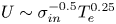 doubling the cross-section gives the same result as decreasing Te by 4 times. It can be reasonable to consider that the double probe method can overestimate Te. Figure 9 also shows the numerical solution of (3.20) by LaPotential taking into account polarization cross-section, space variation of plasma density and electron temperature, and ion temperatures with Ti equal to 0.025 and 0.2 eV. Taking these features into account significantly improved the agreement with the experimental data. Figure 10 shows a comparison of the plasma potential profile calculated using the system of (3.16) with the experimental one under the operation of the thermal cathode with a current of 5.6 A. To exclude the influence of anode processes (not considered in this article), we set the calculated values of the plasma potential at ${r_g} = 25\;\textrm{cm}$
 , equal to the experimental value at this point. In both cases, good agreement was observed between the experimental and theoretical values. All parameters that are used in the theoretical model are summarized in table 2.
Comparison of the plasma potential profile calculated by the system of (3.10) with the experimental one without a thermal cathode.

Comparison of the plasma potential profile calculated by the system of (3.16) with the experimental one under the thermal cathode functioning with a current of 5.6 A.

Input parameters of theoretical model for analytical solution.

5. Discussion
Consider some specific features of the formation of the radial plasma potential following from (3.9), (3.12) and (3.16). From (3.5) it follows that, in the approximation of constant plasma density, the potential profile does not depend on the plasma density. This statement is true for a configuration with a strongly negative equipotential end $(e{U_e} \gg {T_e})$ . Therefore, if the task is simply to obtain a potential difference in the radial direction, then it makes no sense to transfer much energy into the plasma to increase its density. Besides, the plasma potential is proportional to the ion mass raised to the power of −0.75. This means that with the same parameters as presented in figure 5, but with a lighter gas, for example, with helium, a voltage drop 5.6 times greater than that with argon can be obtained.
From (3.12) it follows that the use of a floating intermediate electrode leads to a decrease in the radial electric field. While under a strongly negative electrode, the potential grew as ${r^{3/2}}$ in its dependence on the radius, under a floating electrode it grows only as ${r^{1/2}}$
 . When using a thermionic cathode, in accordance with (3.16), a dependence of the potential on the plasma density appears. A larger plasma density will result in a smaller potential drop at the same emission current. It must be kept in mind that the plasma density inside the thermal cathode domain $r < {r_{\textrm{th}}}$
 can be very different from that at the external region.
Equation (3.20) is written without assuming the uniformity of the spatial distribution of the plasma density. This is important because the density cannot always be considered to be constant. It can decrease by 2 orders of magnitude over several centimetres (Liziakin et al. Reference Liziakin, Gavrikov, Usmanov, Timirkhanov and Smirnov2017), and replacing such a profile with a uniform one can significantly distort the real picture. The good agreement between the calculated profiles and the experiment in the current study is largely due to the fact that the density profile in the experiment was quite flat.
6. Conclusion
The paper considers the problem of creating a radial electric field in a cylindrical plasma column. The case of negative biases is considered. The analytical solutions for the radial potential profile of three most useful electrode configurations are found, by assuming that ion velocity is determined by the E/B relation, and neutral density, plasma density, electron temperature and the elastic collisions cross-section are all constant. In a configuration with a strongly negative equipotential end $(e{U_e} \gg {T_e})$ , it is shown that the plasma potential grows as ${r^{3/2}}$
 . When a floating electrode is added between the negative and the ground electrodes, the plasma potential grows only as ${r^{1/2}}$
 . The mechanism of how the thermionic current at the end allows an increase in the radial potential drop is also shown. An equation is derived for the case when the end electrodes are under potentials close to the plasma potential. The solver LaPotential for the equation is presented which can consider the spatial non-uniformity of electron density and temperature, and the cross-section dependence on ion velocity. To verify the proposed model, an experimental study of the reflex discharge with cold electrodes and with a thermionic cathode was carried out. A comparison of the results of the calculation model with experimental data showed their good agreement.
Declaration of interests
The authors report no conflict of interest.
Funding
This work was partially supported by the Ministry of Science and Higher Education of the Russian Federation (G.L., A.O., MK-2403.2020.2), (State Assignment No. 075-00460-21-00).
Editor Troy Carter thanks the referees for their advice in evaluating this article.
Data availability statement
The data that support the findings of this study are available from the corresponding author upon reasonable request.
Appendix A
Equation (3.20) presented in § 3.4 of this paper can be rewritten as

here ${A_2} = 0.52({n_n}{\sigma _{in}}/LBe){N_{\textrm{surf}}}\sqrt {Mk{T_e}}$ ; ${A_1} = {A_2}\sqrt {2M/{\rm \pi} m}$
 ; ${A_3} = {T_e}$
 ; ${A_4} = {e^2}{B^4}/ {(M{n_n}{\sigma _{in}})^2}$
 ; ${A_5} = B{v_T} = B\sqrt {2k{T_0}/M}$
 , ${T_0}$
 is thermal ion energy.
We consider the cross-section as

where ${\sigma _\infty }$ is cross-section on the infinity of energies, $\alpha$
 is relative polarizability (Raizer et al. Reference Raizer, Kisin and Allen2011).
According to (3.19) in § 3.4, $U({r_{ex}}) = {U_e}({r_{ex}}) - {A_3}\ln ({A_2}/{A_1})$ . Let us denote

After differentiating (A1) with respect to r, we obtain

Excluding $U^{\prime}(r)$ from the (A4) leads to

It is not difficult to show that ${\lim _{r \to 0}}\eta (r) = 0$ . So, from (A3) it follows that $U^{\prime}(0) = 0$
 , consequently in (A5) U’(0) has to take a + sign. Then

This equation must be solved considering the following boundary conditions:


Equation (A6) in conjunction with the boundary conditions (A7)–(A8) solves numerically.
The program LaPotential (Oiler & Liziakin Reference Oiler and Liziakin2021) equation solves by using the shooting method. First, (A6) needs to be solved with boundary conditions (A7). After that we get an assemblage of curves $U(r)$ by varying the values of $U(0)$
 . From this assemblage only one function needs to be chosen which satisfies boundary condition (A8). The search for the desired function is realized by the bisection method.
To solve the Cauchy problem ((A6) with boundary initial condition (A7)), the implicit Euler scheme is used (Dahlquist & Björck Reference Dahlquist and Björck2008):

where h is an integration step, and

If in the system in question there is a floating electrode, where the current density is equal to 0, then the corresponding member of the sum is equal to 0. Value ${U_{N + 1}}$ on the next integration step finds as a solution of nonlinear (A9) by means of the Newton method.



