I. INTRODUCTION
With the development of high-speed cutting, dry and semidry cutting technology, the cutting tools with better performances are required, and the cemented carbide and high-speed steel cutting tool substrate coated with a layer of coating makes the coated cutting tools have higher hardness, wear resistance, and oxidation resistance than the original tools, and the coating would improve service life of the cutting tool effectively. TiN, as the first generation of tool nitride coating, is golden yellow with a hardness of 2300 HV, whose coefficient of friction (COF) reaches 0.45–0.52 under the highest working temperature of 500 °C, and can be used for general metal cutting.Reference Dejun, Yongzhong, Yongzhong and Wenchang1 TiAlN coating based on doping TiN coating by aluminum is the second generation of tool nitride coating with a hardness of 3400–3500 HV, whose COF against a quenched steel ball is about 0.5, and the highest working temperature is 800 °C. Because the atomic radius of Al is smaller than that of Ti, Al atoms exist in TiAlN in the form of replacing Ti atoms in TiN; the lattice distortion not only improves the hardness of TiAlN coating but also intensifies adhesive wear of the cutting tool, reducing the workpiece surface accuracy, which is not suitable for precision machining.Reference Yoon, Kim and Kim2,Reference Chang, Chang and Kao3 To further improve the wear properties of TiAlN coating at high temperatures, Cr element is added into TiAlN coating to form AlTiCrN coating, which belongs to the third generation tool nitride coating. The addition of Cr atoms change a part of the original hexagonal close-packed (Al, Ti)N phase into a harder cubic (Al, Cr)N phase, improving the wear and oxidation resistance of the coating with hardness of 3400–3600 HV, whose COF at room temperature against a ceramic ball is only 0.4. Due to the formation of stable dense α-(Al, Cr)2O3 when the coating works at the high temperatures, the working temperature of AlTiCrN coating can be improved.Reference Santana, Karimi, Derflinger and Schütze4,Reference Kulkarni, Joshi and Sargade5 At the same time, AlTiCrN coating can produce a lubricative oxide film at high temperatures, which is called a self-lubricating coating.Reference Biksa, Yamamoto, Dosbaeva, Veldhuis, Fox-Rabinovich, Elfizy, Wagg and Shuster6 The microstructures, mechanical properties, friction and wear resistance, corrosion resistance, and machining applications of AlTiCrN coating were investigated by many researchers,Reference Liu, Yan, Tian, Yang and Fu7–Reference Kovalev, Wainstein, Rashkovskiy, Fox-Rabinovich, Yamamoto, Veldhuis, Aguirre and Beake10 but the wear failure mechanism of AlTiCrN coating at high temperatures has been rarely researched, therefore, it is necessary to investigate the dry wear behaviors and characteristics of AlTiCrN coating working at high-temperatures. AlTiCrN coatings were prepared on the surface of YT14 cutting tools by a cathodic arc ion plating, and the friction–wear behaviors were tested at 900 and 1000 °C, respectively, providing technical references for dry cutting conditions of AlTiCrN coating.
II. EXPERIMENTAL
The substrate material was YT14-cemented carbide tool, which was placed in acetone and alcohol solution, ultrasonically cleaned for 10 min after sanding to remove the surface impurities and oils, and then dried at constant temperature. The samples were coated on a PVD-coating machine, and the targets of Ti, Al, and Cr with purities of 99.99% were used; the deposition parameters were vacuum of 3 × 10⁻³ Pa, temperature of 500 °C, reaction gas of N2, and the deposition time for 120 min; and after annealing treatment at 180 °C for 2 h with the protection of N2 gas, the samples were cleaned in acetone with a KQ2200DE-type NC ultrasonic cleaner, then ultrasonically cleaned with deionized water, and dried with a hairdryer, and the samples were obtained. The surface–interface morphologies, energy spectrum of the coating surface before and after wear, were analyzed by a SUPRA55-type field emission scanning electron microscopy (FESEM) and its configured EDS (Energy dispersive spectrometer), respectively, the phase compositions of the coating were analyzed by a D/max2500 PC-type x-ray diffractometer (XRD) with the target of Cu, and the coating hardness was measured with a HXD-1000TMC-type Vickers microhardness tester. The element-binding energy was analyzed on a Thermo ESCALAB 250 type X-ray photoelectron spectroscopy; x-ray excitation source type, monochromatic Al Ka (hν = 1486.6 eV); power, 150 W; spot size of x-ray beam, 500 μm; and energy, 30 e. The interfacial bonding strength was measured on a WS-2005-type thin-film adhesion automatic scratch tester, and the test parameters were loading of 0–100 N, loading rate of 100 N/min, and scratch speed of 4 mm/min. The friction–wear behaviors at 900 and 1000 °C were investigated with a HT-1000-type high temperature friction wear tester, and the test parameters were as follows: load of 5 N, temperatures of 900 and 1000 °C, friction radius of 3 mm, friction pair of Si3N4 ceramic ball, rotating speed of 500 rpm, and a wear time of 60 min.
III. RESULTS, ANALYSIS, AND DISCUSSION
A. Surface and interface morphologies
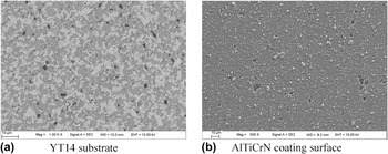
The substrate YT14 is sintered of hard phases (TiC and WC) and the binding phase (Co) at high temperatures, and an obvious grain separation is shown in Fig. 1(a). The white particles are TiC and WC, which are the main reasons for high hardness of the substrate. The surface of AlTiCrN coating has tiny pores on the coating surface, which has little influence on the coating, and no obvious defects, and the uncoated phenomena existed, as shown in Fig. 1(b); the microhardness of coating was 3300 HV, measured by a 2100 TUKON-type microhardness tester under the load of 0.049 N and the action time of 10 s. The fine particles and pits on the coating surface were generated due to the ion-sputtering effect during the arc ion plating deposition,Reference Huijin and Qiang11–Reference Ru, Hu, Huang, Zhao, Qiu and Hu13 which has little influence on the coating surface morphologies.
Surface morphologies of AlTiCrN coating and YT14 substrate.

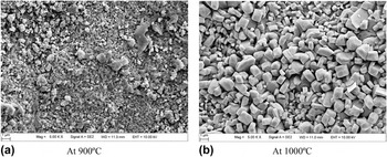
Figure 2(a) shows the surface morphology of AlTiCrN coating oxidized at 900 °C for 1 h, some granular oxide debris of the oxide were formed on the coating surface, and the roughness increased slightly compared with that of the original coating, which was mainly composed of Al, Cr, and Ti oxides. Figure 2(b) shows the oxidized morphology of the coating surface at 1000 °C for 1 h, a lot of flaky and acicular oxides appeared on the surface, and the oxides were mainly composed of Al2O3 and titanium oxides. The size of the oxide particles was more uniform, and they were enlarged when compared to the material tested at 900 °C. According to the Hall–Petch effect,Reference Wo, Munroe, Li, Jiang, Xie, Zhou and Li14 the coating hardness at 900 °C is higher than at 1000 °C, and the wear resistance property at 900 °C was better than at 1000 °C, which can explain the difference of the above surface morphologies.
Surface morphologies of AlTiCrN coating after high temperature wear.

B. EDS and XRD analysis
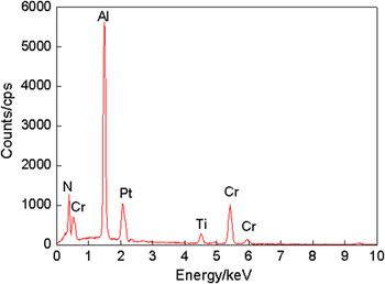
Figure 3 shows the EDS (Energy Disperse Spectroscopy) results of AlTiCrN coating with mass fractions of chemical elements (mass%): Ti, 9.74; Al, 18.57; Cr, 20.54; N, 34.32; C, 9.74; and O, 7.09; and the atomic fractions (at.%): Ti, 3.50; Al, 13.87; Cr, 7.96; N, 49.39; C, 16.35; and O, 8.94; where C and O were the impurities.
EDS analysis of AlTiCrN coating.

During the cathode arc ion plating, the following chemical reactions existed:
 $$2{\rm{Cr}} + {{\rm{N}}_2} \to 2{\rm{CrN}}\quad {\rm{,}}$$
 $$2{\rm{Al}} + {{\rm{N}}_2} \to 2{\rm{AlN}}\quad {\rm{,}}$$
 $$2{\rm{Ti}} + {{\rm{N}}_2} \to 2{\rm{TiN}}\quad {\rm{.}}$$
The thermodynamic process of the coating deposition can be expressed with Gibbs free energy at T = 773 K (500 °C)Reference Wei, Yanhui, Guoqiang, Chuang and Lishi12
 $${G_{\rm{i}}} = {H_{\rm{i}}} - T{S_{\rm{i}}}\quad {\rm{,}}$$
where G i is Gibbs free energy (kJ/mol), H i is enthalpy (kJ/mol), and S i is entropy [kJ/(mol·K)].
According to the thermodynamics handbook, Gibbs free energy of CrN, AlN, and TiN at 773 K can be calculated as −161.2 kJ/mol, −343.4 kJ/mol, and −372.9 kJ/mol, respectively. Therefore, Gibbs free energy of TiN was the minimum; Eq. (3) was most likely to react, so that Ti combined with N ion to form TiN after the target metal ionizing from the target surface, which affected the deposition yield of Ti atom on YT14 substrate, resulting in a smaller content of Ti atoms in the coating with the lowest content of Ti in the EDS analysis results.
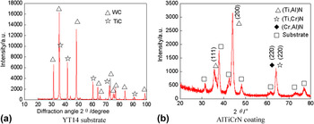
The phases of YT14 hard metal were mainly WC and TiC, as shown in Fig. 4(a). Figure 4(b) shows XRD analysis results of AlTiCrN coating. The coating was mainly composed of (Ti, Al)N, (Ti, Cr)N, and (Cr, Al)N, as the atoms of Al and Cr substitute of Ti atoms in TiN, forming the substitutional solid solution. The highest diffraction peak intensity appeared at the (200) crystal face, indicating that the coating had preferred orientation in the (200) crystal face.Reference Ru, Hu, Huang, Zhao, Qiu and Hu13 The (Cr, Al)N was formed after Cr replaced Ti atoms in (Ti, Al)N, but due to the small atom radius difference of Cr and Ti atoms, the Cr atom with a body-centered cubic lattice, the (Cr, Al)N phase substitutional solid solution, was relatively difficult to produce, therefore, the (Cr, Al)N phase content was low. The (220) crystal was a NaCl-type face-centered cubic (FCC) lattice, which had good ability of resist external stress to prevent grain boundary sliding, improving the spalling resistance and abrasion resistance of the coating. The substrate phase was TiC; the nonmetallic C diffused into the coating during the deposition and combined with Ti ion to form TiC; the metallurgical combination was formed at the interface, which was helpful to improve bonding strength of the coating substrate.
XRD analysis of substrate and AlTiCrN coating.

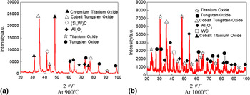
Figure 5(a) shows XRD results of AlTiCrN coating oxidized at 900 °C, the detected Cr and Ti oxides included Cr4Ti4O and Cr3Ti3O, the Co and W oxides were CoWO4, and the Ti oxides included Ti3O5 and TiO, Al oxide of Al2O3, and W oxides included WO3 and W18O49. The Ti oxide in the form of TinO2n−1 was known as Magneli phase, which was a kind of lubricant oxide that can effectively reduce the COF and wear.Reference Veldhuis, Dosbaeva and Yamamoto9 The oxides of Cr and Ti and Al2O3 had ceramic properties with high hardness and low COF, preventing further oxidation.Reference Zhou, Tam, Shum and Li15 The results showed that N element was not detected on the coating surface, indicating that the coating surface had been completely oxidized. The WC phase was detected in the coating, which proved that the coating had worn out, but the oxides on the coating surface had certain protective effects on the substrate for the WC content was low. The phase compositions of AlTiCrN coating after wear under high temperatures were complex, the atoms (Al, Ti, and Cr) in the coating and the atoms (Ti, Co, W, and C) which diffused from the substrate into the coating to react with the O atoms. The Si atom not included in the coating was detected after high-temperature wear, which was in the Si3N4 ceramic ball friction pair diffused at the coating surface, and the Si and C atoms were combined to form SiC. Figure 5(b) shows the XRD results of the coating oxidized at 1000 °C, the detected Ti oxides include Ti4O7, Ti3O5, and TiO; the W oxides included WO3 and W18O49; the Co and W oxides included CoWO4; and the Co and Ti oxides were CoTiO3, and compared with the above results at 900 °C, the WC phase was also detected, indicating the detected position had no AlTiCrN coating, where the coating had been completely worn out, losing the protective effect on the substrate.
XRD analysis of AlTiCrN coating after high temperature wear.

C. Bonding strength
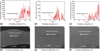
The scratch test method is to use a diamond indenter on the coating surface sliding, the load of L is increased continuously in the process. When it reaches a certain value, the coating and the substrate begin to peel off, the brittle coating will have high strength and continuous wave of acoustic emission signal, and the load value corresponding to the starting point of acoustic emission peaks appearing fluctuation is the critical load of L c, i.e., bonding strength of the coating. The scratch tests of AlTiCrN coating were conducted on a WS-2005-type thin film adhesion strength scratch tester, the critical loading force of L c1, L c2, and L c3 was 59.2 N, 56.35 N, and 57.40 N, respectively, and the changes of acoustic emission intensity enhanced suddenly, as shown in Figs. 6(a)–6(c). Because the bonding strength of AlTiCrN coating is expressed with the average value of loading forces for three scratches, the average bonding strength of AlTiCrN coating was 56.65 N, indicating that the coating had a strong bonding strength with the substrate. The scratched morphologies under the loading forces of L 1, L 2, and L 3 are shown in Figs. 6(d)–6(f), indicating the coating surface start cracking.
Scratched morphologies and interface bonding strength.

At the interface of AlTiCrN coating-substrate of hard alloy, the atoms were adsorbed onto the substrate relying on the adsorption effect of link broken atoms on the substrate, and began to nucleate and grow at these nucleation points, eventually forming the coating,Reference Chen, Yi, Li, Wang and Liu16 which indicated that there was an adsorption combining mode at the bonding interface of the coating substrate. Because of high-temperatures at the coating–substrate interface during cathodic arc ion plating, the mutual diffusion of elements occurred between the coating and substrate to form a diffusion bonding. In the process of diffusion of elements, the gradient diffusion layer of Ti, Cr, Al, N, and Ti elements formed at the bonding interface. The C atoms in the substrate were diffused into the TiN, AlN, and CrN lattice, while N atoms in the coating diffused into the TiC lattice of the substrate, and TiCN, AlCN, and CrCN were generated to form chemical bonds.Reference Chen, Zeng, Qiu, Dong, Li and Huang17 Therefore, the combining mode of coating–substrate consisted of adsorption bonding, diffusion bonding, and chemical bonding, which led to superior bonding strength between the coating and the substrate.
D. COF
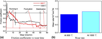
Figure 7(a) shows the relationship between COFs and wear time of AlCrTiN coating at 900 and 1000 °C; the average COF of AlCrTiN coating at 900 °C was 0.42, while that of AlCrTiN coating at 1000 °C was 0.45, showing that the friction and wear properties of the coating became excellent with the increase of working temperature, and the AlTiCrN-coated cutting tools were suitable for high temperature dry cutting above 900 °C. The wear processes were divided into three stages, such as running-in, fluctuation, and stabilization: (1) At the running-in stage, the surface roughness of AlCrTiN coating was relatively large, the COFs were increased at first, after a short of running-in, the convex peaks on the coating surface had been polished, and the COF showed a downward trend. The average COF of the running-in stage (0–20 min) at 900 °C was 0.68, while that of the running-in stage (0–15 min) at 900 °C was 0.62, and the two COFs were basically approached. (2) At the fluctuation stage, as the wear continues, the formation of Al2O3, titanium oxides, and chromium oxides increased on the coating surface, which played a role in lubrication and the COF decreased in some way.Reference Tam, Zhou, Shum and Li18 The average COF of the fluctuation stage (20–50 min) at 900 °C was 0.31, because the oxide particles of the coating at 1000 °C were more than those at 900 °C, leading to abrasive wear of friction pair, as a result, the average COF of the fluctuation stage (15–50 min) increased to 0.44. (3) At the stabilization stage (50–60 min), the COFs at 900 and 1000 °C were decreased to 0.27, indicating that AlTiCrN coating had better cutting performances at the high temperatures. From Fig. 7(b), it can been seen that the wear rate of AlTiCrN coating at 900 °C was 1.16 × 10⁻⁵ mm3/N, while the wear rate of AlTiCrN coating at 1000 °C was 1.34×10⁻⁵ mm3/N, increased by 15.5%, which indicates that AlTiCrN coating exhibited excellent wear performance at 900 °C. When the wear temperature increased, the wear resistance decreased in some way, which is due to the increase of adhesive wear at high temperatures.
Results of friction-wear test.

E. Wear morphologies
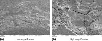
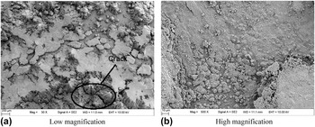
Figure 8 shows the surface morphologies of AlTiCrN coating after wear at 900 °C for 1 h, the scar width was about 500 μm with some debris on the worn scar, as shown in Fig. 8(a), and the main components were oxides, indicating that some abrasive wear and oxidation wear occurred on the coating surface. Meanwhile, the solid phase bonding appeared on the coating surface after the materials transferred during the wear, and the locally thickened phenomena appeared on the coating surface, which was the performance of adhesive wear phenomena at high temperatures.Reference Tam, Zhou, Shum and Li18 Under the condition of dry friction at high temperatures, the coating contacted with the friction pair, and some microfurrows, oxidation phenomena and cracks appeared, as shown in Fig. 8(b), which was due to the fatigue failure caused by loading and unloading of the friction load, leading to the coating to produce internal stress. But the large spalling phenomena did not appear on the coating surface, which still had a certain protective effect and excellent antifriction performance for the substrate. Therefore, the wear mechanism of the coating at 900 °C was the combination of fatigue wear, oxidation wear, abrasive wear, and adhesive wear at high temperatures.
Morphologies of worn scar on AlTiCrN coating surface at 900 °C.

Figure 9 shows the surface morphologies of AlTiCrN coating after wear at 1000 °C for 1 h, which was softened at the high temperature and severe plastic deformation generated, resulting in a large number of cracks [Fig. 9(a)], and the coating surface had been oxidized severely with a large number of particulate worn debris [Fig. 9(b)]. The oxides on the coating surface formed a friction pair with the ceramic ball after wear, the cracks expanded into the inside of the coating, and the surface was almost oxidized, losing efficacy and protection of the substrate. Compared with the surface morphologies in Fig. 8(a), the worn surface at 900 °C is more smooth, which is the main reason for the small average COF of the coating at 900 °C. The above results showed that the wear mechanism of coating at 1000 °C was the combination of fatigue wear, oxidative wear, abrasive wear, and adhesive wear.
Morphologies of worn scar on AlTiCrN coating surface at 1000 °C.

F. Plane scan analysis of the scars
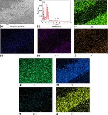
The plane scans of AlTiCrN coating were used to analyze the distributions of chemical elements after wear at 900 °C, whose detected position is shown in Fig. 10(a), and the result is shown in Fig. 10(b); the mass fractions of chemical elements (mass%) were as follows: Al, 5.72; Ti, 3.42; Cr, 14.86; C, 27.71; O, 24.95; Si, 0.98; Co, 6.72; and W, 15.65, and the atomic fractions (at.%) were as follows: Al, 4.54; Ti, 1.53; Cr, 6.12; C, 49.40; O, 33.40; Si, 0.74; Co, 2.44; and W, 1.82. Figures 10(c)–10(f) show the element distributions evenly beyond the worn scar, indicating that the coating had good wear properties. Compared with the origin coating, the Si, Co, and W atoms were detected additionally, N was not detected, in which Si in the friction pair of Si3N4 ceramic ball diffused into the coating, and Co and W were the elements of the YT14 substrate,Reference Feng, Zhang, Ke, Wan, Wang and Lu19 showing that the coatings had been worn out, and TiC, WC, and Co in YT14 tools were oxidized at high temperatures to form oxides on the worn surface. Figure 10(c) shows the plane scan result of the Al element, the Al content inside the worn scar was extremely lower than that outside the worn scar, which proved that the coating had worn out on the worn scar, and the detected Al came from the residual Al oxides. Figure 10(d) shows that the plane scan result of Ti atom inside the worn scar was the same as that in other positions, which was because the TiC content in the YT14 tools was 14% higher than that in the coating, and the content of Ti inside the worn scar mainly came from the substrate. The plane scan results of Cr and N inside the worn scar are shown in Figs. 10(e) and 10(f), lower than that outside the worn scar, indicating that the coating had been worn out. Figure 10(g) shows the plane scan result of O element that distributed evenly on the coating surface, showing that the coating surface was oxidized equally. Figures 10(h) and 10(i) show the plane scan results of W and Co that had a high content inside the worn scar, indicating that the metal elements of the substrate also generated the oxides on the worn surface. Figure 10(j) shows the plane scan results of the Si element that was very high inside the worn scar, which was due to the diffusion of Si of the Si3N4 ceramic ball.Reference Ru, Hu, Huang, Zhao, Qiu and Hu13 The above results showed that AlTiCrN coating had worn out at 900 °C for 1 h, and the generated oxides had a certain protective effect on the substrate.
EDS analysis of AlTiCrN coating on worn surface at 900 °C.

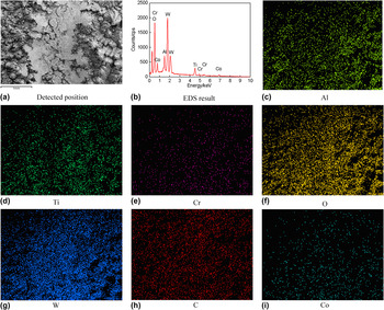
Figure 11 shows the plane scan results of AlTiCrN coating after wear at 1000 °C for 1 h, whose detected position is shown in Fig. 11(a). The plane scan result is shown in Fig. 11(b), and the mass fractions of chemical elements (mass%) shown are as follows: Al, 2.27; Ti, 7.29; C, 21.18; O, 29.9; Co, 10.42; and W, 28.85, while the atomic fractions (at.%) shown are as follows: Al, 2.00; Ti, 3.62; C, 41.91; O, 44.54; Co, 4.20; and W, 3.73, and the Cr content is too low to show because of being worn out at the high temperature. Compared with the result in Fig. 10(b), the increase of O atom indicated that the coating had been oxidized more seriously, and the decrease of Al atoms and the increase of Ti atom showed that the worn scar deepened. The scan result of Al, Ti, and Cr elements in Figs. 11(c)–11(e) was lower than that in Figs. 11(c)–11(e), respectively, which came from the coating oxides. The content of O atom was very high in Fig. 11(f), the loosely coupled oxides with low intensity were generated at 1000 °C, losing the protective effect on the substrate. The contents of W, C, and Co in the substrate were high in Figs. 11(g)–11(i), showing that the substrate elements had been oxidized after the coating wearing out.
EDS analysis of AlTiCrN coating on worn surface at 1000 °C.

IV. CONCLUSIONS
(1) AlTiCrN coating is composed of Al, Ti, Cr, and N elements, the phases are mainly AlN, CrN, and TiN that have strong preferred orientation in the (111) crystal plane, whose microhardness is 3300 HV.
(2) The coating had a high bonding strength of 57.65 N with the substrate measured by a scratch method, mainly due to the combining action of adsorption bonding, diffusion bonding, and chemical bonding at the bonding interface.
(3) Under the lubricative effect of Al2O3 and Magneli phase titanium oxide TinO2n−1 generated at high temperatures, AlTiCrN coating shows good friction properties with an average COF of 0.42 and 0.45 at 900 and 1000 °C, respectively.
(4) The phenomena of coating oxidation occur at 900 and 1000 °C, the generated oxides have a protective effect on the coating, the wear mechanism was mixed form of fatigue wear, oxidation wear, and abrasive wear, whose maximum working temperature is between 900 and 1000 °C.
(5) AlTiCrN coating has been worn out after wear at high temperatures for 1 h, and the obvious enrichment and depletion area of chemical elements appear on the worn scar, showing a uniform wear form.
ACKNOWLEDGMENTS
Financial support of this research by Jiangsu Province Science and Technology Support Program (Industry) (BE2014818) is gratefully acknowledged.