NOMENCLATURE
Acronyms
- ACC
Air Cargo Challenge
- ACSYNT
AirCraft SYNThesis
- AIAA
American Institute of Aeronautics and Astronautics
- APAE
Portuguese Association of Aeronautics and Space
- CAD
computer-aided design
- CFRP
carbon-fibre-reinforced plastic
- C-MAST-UBI
Centre for Mechanical and Aerospace Science and Technologies
- DCA
Aerospace Sciences Department
- EPS
expanded polystyrene
- FAME-W
Fast and Advanced Mass Estimation Wing
- FEM
finite element method
- GRG
generalised reduced gradient
- MDO
multidisciplinary design optimisation
- NASA
National Aeronautics and Space Administration
- PDCYL
point design of cylindrical-bodied aircraft
- PVC
polyvinyl chloride
- UAV
unmanned aerial vehicle
- UBI
University of Beira Interior
- USA
United States of America
- WAATS
Weights Analysis for Advanced Transportation Systems
Symbols
- A
aspect ratio
- A
area (m2)
- A i
characteristic parameters
- b
wingspan (m)
- c
coefficients
- c
chord (m)
- C
geometric parameters
- CG
centre of gravity
- C m
pitching moment coefficient
- dC L/dα
lift curve slope of the wing
- ds
infinitesimal distance around the cell wall
- E
Young’s modulus (Pa)
- f
correction factor
- F combined
combined aircraft objective function
- F individual
single aircraft objective function
- G
shear modulus (Pa)
- GJ
torsion rigidity (Nm2/rad)
- I XX
second moment of area around x-axis (m4)
- K
coefficients
- k
constant
- l ht
tail arm (m)
- l tb
tail boom length (m)
- m
mass (kg)
- M
bending moment (Nm)
- n
limit load factor
- n a
number of aircraft
- n data
number of data
- n m
number of mass components
- n panels
number of panels
- n par
number of parameters
- P
perimeter (m)
- p(x)
chordwise load distribution (N/m)
- Q
shear force (N)
- q
dynamic pressure (Pa)
- q
shear flow (N/m)
- r
radius (m)
- R 2
coefficient of determination
- S
planform surface area (m2)
- SF
safety factor
- S winglet/S wing
winglet area ratio (winglet area divided by wing area)
- t
thickness (m)
- t/c
thickness-to-chord ratio
- W
weight (N)
- w z
spanwise lift distribution (N/m)
- x
position along the chord line (m)
- x spar
position of the spar (m)
 ${\bar x_e}$
non-dimensional elastic centre position
- ${\bar x_spar}$
non-dimensional position of the spar
- y
position along wing semi-span (m)
- $d\theta /dy$
twist rate (rad/m)
- $\beta $
slope (rad)
- $\gamma $
area mass (kg/m2)
- $\delta $
deflection (m)
- $\theta $
twist angle (°)
- $\rho $
density (kg/m3)
- $\sigma $
direct stress (Pa)
- $\tau $
shear stress (Pa)
- $\omega $
chordwise lift distribution (N/m)


Subscripts
- A
area
- aerofoil
aerofoil
- box
D-box
- calculate
calculated
- cb
cargo bay
- empty
empty
- est
estimated value
- film
wing covering film
- fus
fuselage
- gear
landing gear
- ht
horizontal tail
- $I,II $
aerofoil section cells
- i,j
counters
- le
leading edge
- max
maximum
- P
perimeter
- panel
wing panel
- pay
payload
- R
Rth wing section cell
- real
real or reported value
- rib
rib
- root
root
- sandwich
wing sandwich
- skin
wing skin
- skin_core
wing skin sandwich core
- skin_face
wing skin sandwich face
- spar
spar
- spar_cap
spar cap
- spar_core
wing spar sandwich core
- spar_face
wing spar sandwich face
- spar_web
spar web
- sys
systems
- tb
tail boom
- te
trailing edge
- tip
wing tip
- tube
tube spar
- vt
vertical tail
- wing
wing
- winglet
winglet
- x,y,z
Cartesian system coordinates

Superscripts
- fl
flight
- div
divergence
- gd
ground
- tb
tail boom
- $\sigma $
due to direct stress
- $\delta $
due to tip deflection
- $I,II $
aerofoil section cells
- $\theta $
due to twist angle
- $\tau $
due to shear stress
- T
due to torsion moment


1.0 INTRODUCTION
Having accurate mass estimates at the early stages of aircraft design has been shown to be crucial to maintain the capability to perform mission sizing without increasing the take-off mass(Reference Raymer1). For any type of aircraft, the preliminarily obtained mass value is essential to define and calculate further design parameters.
Many mass models have been proposed over the years: some with a more general scope and others being specific to a particular aircraft type, some more appropriate for conceptual design work and others more detailed in their formulation. A division in classes, based on the complexity of the mass model, detailed below, was elaborated by Elham et al.(Reference Elham, La Rocca and Van Tooren2) and presented by Dababneha and Kipouros(Reference Dababneh and Kipouros3) in a review of existing methods.
Class I: In this class, the equations representing the mass are essentially developed from statistical data as functions of parameters such as empty mass, payload and fuel mass. In this situation, the initial data are scarce, and usually only the required range and speed of the aircraft are available, resulting in simple equations with high associated error when compared with other, more effective methods. Methods in this class have been presented by Roskam(Reference Roskam4), Jenkinson(Reference Jenkinson, Simpkin and Rhodes5), Raymer(Reference Raymer1) and Torenbeek(Reference Torenbeek6), and Weights Analysis for Advanced Transportation Systems (WAATS), the program developed by the National Aeronautics and Space Administration (NASA)(Reference Glatt7).
Class II: As in class I methods, these are based on statistical data. However, in this case, the designer has access to information regarding the influence that his choices, related to geometry and other aspects of the components, will have on the final mass of the aircraft. Semi-empirical relationships based on essentially geometric characteristics are used and may or may not be divided into components (fuselage, wing, tail and landing gear). Examples of these methods have been presented by Torenbeek(Reference Torenbeek6), Raymer(Reference Raymer1), Niu(Reference Niu8), Jenkinson(Reference Jenkinson, Simpkin and Rhodes5) and Howe(Reference Howe9).
Class III: In this class, physics based on structural analysis is used rather than statistical data. Usually, the Finite Element Method (FEM) is used. The various components are sized based on the structural requirements, and the mass is calculated based on the volumes and densities of the materials to be used. Examples include the works elaborated by Bindolino(Reference Bindolino, Ghiringhelli, Ricci and Terraneo10) and Ardema et al.(Reference Ardema, Chambers, Patron, Hahn, Miura and Moore11), who developed the Point Design of Cylindrical-bodied Aircraft (PDCYL) program, integrated into the AirCraft SYNThesis (ACSYNT) program developed by NASA.
Class IV methods are also presented and described as being developed for use outside the conceptual design zone and preliminary design. These are more detailed methods, based on FEM, than those in class III, adding Computer-Aided Design (CAD) models and components from catalogues and suppliers to the mass calculation.
A fifth class is also presented in between class II and III, known as class II½. This class comprises semi-empirical methods that use elemental analysis, based on the stiffness and mechanical strength of the materials, combined with statistical data. The amount of material required to withstand stress is calculated using simple structural equations. Examples include the works of Burt(Reference Burt12), Torenbeek(Reference Torenbeek13), Elham et al.(Reference Elham, La Rocca and Van Tooren2), FAME-W (Fast and Advanced Mass Estimation Wing) software developed by Airbus Germany(Reference van der Velden, Kelm and Mertens14) and Dijk(Reference can Dijk15), who created a program for Airbus Industry in Toulouse.
The examples described above indicate that the evolution of the computational capacity associated with the refinement of existing methods has resulted in greater accuracy. Also note the existence of methods developed by authors that appear associated with design books, as well as models developed and applied by companies that use their aircraft data and then, via exchange with competitors, have access to more data, allowing more accurate results. One also observes the difference between types of methods, both in terms of their complexity and in the way they are presented; that is, there are models from which an estimate is obtained for the total weight of the aircraft, others where it is possible to determine an estimate for each constituent group and also estimates by component or set of components. There are also some examples of methods developed specifically for prediction of the mass of the wing, a critical component in any type of aircraft(Reference Ardema, Chambers, Patron, Hahn, Miura and Moore11).
In the examples presented in aircraft design books, it is possible to observe a division of the models associated with each type of airplane by its application(Reference Raymer1,Reference Torenbeek6) . Note also that, for most models, the range of applicability is specified, that is, the size limitation in terms of geometry or mass for which they have been developed and consequently for which they are valid.
The Air Cargo Challenge (ACC) is a biannual competition for universities, taking place in Europe, whose main objective is to design, build and fly a radio-controlled aircraft(16) over a period of around 6 months, similar to the design/build/fly competition sponsored by the American Institute of Aeronautics and Astronautics (AIAA)(17) in the United States of America (USA). The ACC competition was created in 2003 by the Portuguese Association of Aeronautics and Space (APAE) for Portuguese universities only and took place in Lisbon, Portugal. In 2007, the event was opened to all European countries to encourage widespread participation and promote exchange of knowledge regarding aircraft design among students and their institutions. Since 2013, teams outside Europe have been allowed to participate, and positive results have been obtained from the recent participation of universities outside Europe from countries such as China and Brazil.
Regarding the competition itself, the development and construction of a radio-controlled aircraft capable of carrying the maximum payload mass possible is required. In the flight competition, the aircraft must take off from a distance equal to or less than 60m, make at least one turn around the airfield and land safely, so that the flight can be considered valid. In this situation, the aircraft with the largest possible span, least empty mass and highest lift-to-drag ratio at low speeds is preferred. In addition to these objectives, from the 2015 edition onwards, the need to perform a high-speed flight in a racetrack format was included, coupling the capability to carry a heavy payload with the capability to fly as fast as possible. With these changes, different new airframe requirements appeared, such as increased stiffness to prevent undesired aeroelastic phenomena and improved aircraft surface quality to reduce friction drag. Large-span and low-mass aircraft are still preferred, even though the best aerofoil has reduced camber and thickness for the high-speed flight and flaps may be required for take-off and climb segments to provide high lift coefficients without significantly affecting the lift-to-drag ratio. Pilot skill has also become a major factor. Limits on some parameters, such as wingspan, wing area, motor type, propeller size and model or empty mass, have been imposed by the regulations in some previous events. These or various combinations of these have changed over the years to promote an increase in the number of participants, since this makes it necessary to develop a new design for each competition edition. There are some other requirements in the ACC regulations that have been consistent over the years. All teams must use the same brand and model of electric motor and of propeller, which implies that all the aircraft will have essentially the same maximum installed thrust. Also, fast loading of the payload (typically made of steel plates) into the cargo bay provides extra points. Therefore, a simple fuselage with easy access to the cargo bay is needed. Another important requirement that affects the design is that the aircraft must be disassembled into small parts to fit inside a transportation box of given size. This imposes constraints on the maximum size of the aircraft and leads to increased airframe mass due to the interface connections needed to join wing panels and fuselage parts. Safety constraints also affect the aircraft design. The aircraft must exhibit a positive static margin irrespective of the position of the Centre of Gravity (CG), although a fixed CG position is usually advised in the regulations. This requirement together with the need for high lift coefficients at take-off and low mass usually favours a conventional configuration with a nose propeller, forward high-span wing and aft tail on a single tail boom. Also, the aircraft must undergo a ground load test in which it is suspended by its wing tips when fully loaded. This test is representative of a wing root bending moment for a longitudinal manoeuvre with a load factor of 2, even though the shear force outboard the mid-span point corresponds to higher load factors.
All in all, the goal of the flight competition is to maximise the score of the team, given by a multi-objective function subject to the constraints mentioned above. This function is optimised by maximising the payload mass carried, minimising the time required to cover the racetrack distance, minimising the time needed to load the payload into the cargo bay and minimising the difference between the estimated and the actual carried payload mass. These four objectives have different weights, with the first two having similar values and higher weights than the other two.
In the early editions of the competition, the airplanes had structures made, essentially, of balsa wood and covering film with the aim of imparting mechanical resistance and shape, respectively. There were also others made of fibreglass and foam. The introduction of more extensive use of composite structures occurred in the 2007 edition, in which it was possible to observe the existence of composite carbon fibre tubes used for the tail boom. Due to the more adequate mechanical properties of this type of structure for the evolving requirements of the competition, the use of composites has extended to other components of the aircraft. The main change was in the wing structure, namely the wing spar, which has become initially a Carbon-Fibre-Reinforced Polymer (CFRP) tube, thus providing increased bending and twisting strength with an advantageous decrease in weight. The need to increase the strength of the wing even further resulted because more complex flaps started to be used and higher speeds were achieved. The use of carbon fibre composites was extended to a greater percentage of the wing, including spars and skins. It is also worth noting that reinforcements to the leading and trailing edges, typically made of balsa wood, use glass fibre or carbon composites in more recent aircraft.
Regarding the fuselage, typical configurations can be divided into two main cases: full-length tube, to which the cargo bay is attached underneath, and traditional fuselage, where the payload is placed in an interior cargo bay and a tail boom is used for the remaining length. The cargo bay is essentially made of balsa wood and covering film or composite.
Several philosophies are applied for the construction of the landing gear, with two preferred layouts. One is a two-wheeled tail dragger configuration with the wheels connected by a tube or rod, often in CFRP, and the other is a tricycle configuration with main and secondary forward landing gears. Note also the differences in the complexity of the landing gear component, with the existence of simple structures and others developed with special attention to the preservation of the integrity of the aircraft, since there is a need to avoid damaging it in any way, which could prevent future flight attempts or even cause disqualification of the flight.
As for the planes’ tail surfaces, it is seen that, despite the increased use of composite structures, the magnitude of the forces in these components is much lower, in comparison with the wing, meaning that most structures are similar to those used in the beginnings of the competition, i.e., using balsa wood and covering film, resulting in very low masses.
The Aerospace Sciences Department (DCA) of the University of Beira Interior (UBI) has a major interest in the ACC competition. Having participated in all its editions to date, with three wins (two since the competition became international in 2007), it has become a very important event to improve knowledge and apply new aircraft design models and manufacturing techniques, essential to develop highly optimised designs.
Several aspects of the design affect the overall performance of the aircraft, though probably the aerodynamic shape and mass play a major part. The maximum take-off mass is primarily dependent on the aerodynamic design, propulsion system performance and wing size and geometry. The empty mass is affected by the size and geometry of the aircraft as well as by the structural configuration, used materials, manufacturing techniques, mechanical parts design and team’s budget. From previous flight competitions, it has been observed that teams seldom achieve their estimated payload mass, which can be partly justified by poor empty mass estimates, inadequate aerodynamic performance prediction or poor airframe construction, which affects aerodynamic shape and structural mass and strength. In this competition, experience has demonstrated to be the major factor for correct estimation of aircraft mass. However, since in ACC the empty mass to take-off mass ratio is unusually low (in the range of 0.15–0.35), a synthesis of adequate mass prediction models can help improve the estimates for less experienced teams. Also, to further optimise new aircraft designs using numerical frameworks, such more accurate mass models are essential. So, the main objective of this work is to develop two mass prediction models that can be used in the design of aircraft for the ACC competition, and for other similar aircraft, the first in the early design process and the second in more advanced design phases. The integration of these more accurate, yet simple, mass models into the design process of the aircraft can improve take-off mass and empty mass estimates and help optimise future designs.
In Section 2, the mass models are introduced, including an explanation of the geometric parameters and implemented methods. In Section 3, a simplified structural sizing methodology is presented, based on three wing structural concepts, to be used in the structure-based mass model. Then, in Section 4, the results obtained for the developed mass models are presented, accompanied by an analysis focused on the errors, accuracy and validity of each model. Finally, in the conclusions, an overview of the developed work and its main conclusions are presented.
2.0 MASS MODELS
In this section, the mass models are introduced. The equations for the models, comprising the mathematical methods and the necessary considerations and simplifications, are presented. First, a simple class I model then a more detailed class II½ model are developed.
2.1 Statistical mass models
To determine the equations required for each model presented hereafter, it is necessary to define the method adopted based on the conducted research. Since the parameters used to describe the system are assumed to be independent, the equation considered adequate to represent the mass,  $m$, has the following form:
 \begin{align}m = k\prod\limits_{i = 1}^{{n_{par}}} {a_i^{{c_i}}} \end{align}
where  $k$ is a constant, c i are coefficients, a i are characteristic parameters of the system and n par is the number of parameters.
To find the values of k and a i in Eq. (1), it is necessary to minimise the error between the mass estimated by the model and the real mass of a sufficiently large number of aircraft. Thus, the following objective function is used to determine the unknown coefficients:
 \begin{align}f = \sum\limits_{j = 1}^{{n_{data}}} {{{\left( {\frac{{{m_{est,j}}}}{{{m_{real,j}}}} - 1} \right)}^2}} \end{align}
where m est is the estimated mass given by the model in Eq. (1), m real is the real mass and n data is the number of data used to build the model.
Any appropriate method can be used to minimise f. In this case, the nonlinear Generalised Reduced Gradient (GRG) method(Reference Lasdon, Fox and Ratner18) embedded in Excel Solver is applied.
The coefficient of determination, R 2, is the proportion of the variance in the dependent variable that is predicted by an independent variable. A value close to 1 indicates an adequate fit to the data. If R 2 has a value near 0, the fitting does not represent the data properly(Reference Cameron and Windmeijer19). The coefficient of determination is calculated from
 \begin{align}{R^2} = 1 - \frac{{\sum\limits_{j = 1}^{{n_{data}}} {{{\left( {{m_{est,j}} - {m_{real,j}}} \right)}^2}} }}{{\sum\limits_{j = 1}^{{n_{data}}} {{{\left( {{m_{real,j}} - {{\bar m}_{real}}} \right)}^2}} }}\end{align}
where  ${\bar m_{real}}$ is the mean of the real masses.
This is a class I model, whose developed equation has the form shown below, where the unknown values are determined by implementing the methodology described above. In this study, only three parameters characterising the system are used, thus
 \begin{align}m = ka_1^{{c_1}}a_2^{{c_2}}a_3^{{c_3}}\end{align}
where the variables a 1, a 2, a 3 represent wingspan, b, wing chord, c, and payload mass, m pay (or wing area, S, aspect ratio, A, and payload mass), respectively(Reference Noth, Siegwart and Engel20).
2.2 Structure-based mass models
These class II½ models are based on equations that relate the geometric and mechanical characteristics of the components of an aircraft with the forces and moments to which it is subjected. The expressions obtained allow the determination of the quantity of material, for certain expected operating conditions, necessary to fulfil the specified mission. It is then possible to obtain the resulting mass of each component by summing the structural element sizes obtained to resist each force or moment, as explained in Section 3.
Since all this calculated material mass is required to withstand the loads, some mass penalty factors related to the interfaces required to join different components and extra material needed to bond different elements are defined so that the final mass obtained for the wing is adjusted to be more precise.
This section describes in detail the derivation of the mass models based on the type of structure selected, the most important component being the aircraft wing because it is typically the aircraft component with the greatest mass. First, the general aircraft and wing geometry is defined, followed by an introduction of the three wing structural concepts used in this study together with their characteristic geometric parameters. Some relationships involving those geometric parameters are presented as functions of wingspan, chord length, aerofoil thickness-to-chord ratio and tail arm because these main parameters can be used as design variables in a design framework. The mass models for the wings, fuselage, tail and other components are then presented.
2.2.1. Aircraft geometry
Many aircraft layouts are possible, but due to the mission requirements of ACC aircraft, the most common is the conventional layout with an unswept or low-sweep high-aspect-ratio wing and an aft tail at the end of a slender tail boom (Fig. 1). The main parameters that define the aircraft are the wingspan, b, wing chord, c, tail arm, l ht, tail boom length, l tb, wing planform area, S wing, horizontal tail area, S ht, and vertical tail area, S vt. An orthogonal xyz coordinate system is selected with its origin placed at the leading edge of the wing root chord. The x-axis points towards the tail, the y-axis points to the right wing and the z-axis points upwards.
Typical ACC aircraft geometry.

Since different tail arms may be used during the design process, it is convenient to define some characteristic non-dimensional parameters based on a reference wing with given chord length c wing and span b wing. The ratio b wing/c wing is the aspect ratio A wing. It is then possible to define two coefficients that are directly proportional to the reference wing aspect ratio, one for the tail arm and another for the tail boom length, in the form
 \begin{align}K_{ht}^{} = \left( {\frac{{{l_{ht}}}}{{{c_{wing}}}}} \right){A_{wing}}\end{align}
 \begin{align}{K_{tb}} = \left( {\frac{{{l_{tb}}}}{{{c_{wing}}}}} \right){A_{wing}}\end{align}
From Eq. (5) and Eq. (6), it is possible to obtain the tail arm and the tail boom length, respectively, for any sized wing from
 \begin{align}{l_{ht}} = K_{ht}^{}c\end{align}
 \begin{align}{l_{tb}} = K_{tb}^{}c\end{align}
where c is the actual wing mean chord. In general terms, the wing chord may be defined by its mean chord. If the chord of the wing is constant along the span and equal to the mean chord, it may be assumed that only one wing panel exists as in Fig. 2(a). In this case, the characteristics of the wing cross-section may be defined at the root of the wing and are constant spanwise.
Wing planform shapes: (a) constant-chord (single panel) wing example and (b) tapered (multiple panels) wing example.

However, in most ACC aircraft, the wings have taper. This implies a spanwise chord change, which might have a constant taper or a varying taper. In both cases, the wing is composed of panels (Fig. 2(b)). In this case, the sizing may be done for the first panel, with the characteristics of the remaining sections being determined based on the first panel size and local loads. In general, the sizing is done at the panel root, so the characteristics are constant throughout the panel.
2.2.2. Wing structural concepts and cross-section geometry
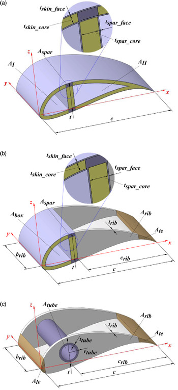
Based on the observation of the different wing structures used in ACC aircraft, three different wing structural concepts are considered in this study, namely load-bearing skin concept, D-box wing concept and circular tube spar wing concept. The concepts of these wing structures and the corresponding geometric and sizing parameters are shown in Fig. 3.
Structural wing concepts representation: (a) load-bearing skin wing, (b) D-box wing and (c) circular tube spar wing.

The load-bearing skin wing concept (Fig. 3(a)) represents a monocoque skin wing with a single spar. The complete skin is made of a sandwich with two faces of constant thickness t skin_face each and a core of constant thickness t skin_core. The two spar caps are a unidirectional laminate with cross-section area A spar, while the spar web is also a composite sandwich with two faces of thickness t spar_face each and a core of thickness t spar_core. This configuration forms a two-cell closed-section beam.
The D-box wing concept (Fig. 3(b)) is divided into two distinct parts. The forward part, from the leading edge to the single spar, is similar to the previous concept and forms a closed section, the so-called D-box. The aft part is made of balsa wood ribs with thickness t rib and lateral area A rib spaced at constant intervals b rib and a balsa wood trailing-edge stringer of cross-section area A te. The complete wing is covered by a thin film of thickness t film that closes the aft part and gives the wing its aft aerodynamic shape. This configuration forms a single-cell closed-section beam.
In the circular tube spar wing concept (Fig. 3(c)), the composite circular tube spar resists all wing loads. Its cross-section dimensions are wall thickness of t tube, radius of r tube and section area of A tube = Πr tube2. The aerodynamic shape of the wing is given by balsa wood ribs and leading-edge and trailing-edge stringers with cross-section area of A le and A te, respectively. In this concept, the complete wing is also covered by a thin film of thickness t film to close it and form the aerodynamic shape.
There are further cross-section parameters that are required for the full definition of the cross-section, namely the aerofoil’s chord, c, thickness-to-chord ratio, t/c, cross-section area, A aerofoil, and perimeter P aerofoil. In the load-bearing skin wing concept, the forward cell has perimeter p I and cross-section area A I while the aft cell has perimeter P II and cross-section area A II (Fig. 4(a)). Finally, the perimeter and cross-section area of the D-box are P box and A box, respectively (Fig. 4(b)).
Further geometric parameters for the composite sandwich skin concepts: (a) load-bearing skin wing and (b) D-box wing.

The aerofoil selected for the wing provides the geometry of the wing cross-section. Since different aerofoil sizes may be used in the wing during the design process, it is convenient to define some characteristic non-dimensional coefficients for the aerofoils based on a reference aerofoil with given chord length c aerofoil, thickness-to-chord ratio (t/c)aerofoil, cross-section area A aerofoil and perimeter P aerofoil. Based on these reference parameters, it is possible to define two coefficients. The first coefficient is associated with the cross-section area and is inversely proportional to the chord squared and to the thickness-to-chord ratio. It is defined by
 \begin{align}{K_A} = {{{A_{airfoil}}} \over {{{(t/c)}_{airfoil}}c_{airfoil}^2}}\end{align}
Assuming that the thickness-to-chord ratio varies only slightly with the aerofoil perimeter, the perimeter-associated coefficient is only a function of the chord, thus
 \begin{align}K_P^{} = \frac{{{P_{airfoil}}}}{{{c_{airfoil}}}}\end{align}
Based on the coefficients K A and K P, it is possible to obtain coefficients for any cross-section area or perimeter ratio between 0 and 1 based on the total cross-section area and perimeter, respectively, of any geometrically identical aerofoil. Thus, general area and perimeter coefficients may be used in the form
 \begin{align}K_{A,i}^{} = \left( {\frac{{{A_i}}}{{{A_{airfoil}}}}} \right){K_A}\end{align}
 \begin{align}K_{P,i}^{} = \left( {\frac{{{P_i}}}{{{P_{airfoil}}}}} \right){K_P}\end{align}
where i represents any element of the wing cross-section, such as a trailing-edge stringer or a D-box. If i is omitted, then the complete aerofoil is considered.
For the load-bearing skin wing concept, i in Eq. (11) and Eq. (12) represents either cell I or II. The ratios A i/A aerofoil depend on the x-position of the wing spar and A I/A aerofoil + A II/A aerofoil = 1. If A I/A aerofoil is specified, then
 \begin{align}\left( {\frac{{{A_{II}}}}{{{A_{airfoil}}}}} \right) = 1 - \left( {\frac{{{A_I}}}{{{A_{airfoil}}}}} \right)\end{align}
In the case of the D-box wing concept, there is only one cell, the D-box itself. Coefficients in Eq. (11) and Eq. (12) are used for the D-box by substituting i with box, as shown in Fig. 4(b), giving K A,box and K P,box. Also, the rib and the trailing-edge stringer require a geometric non-dimensional coefficient associated with the cross-section area. In these components, Eq. (7) is used by substituting i with le or te for the leading- and trailing-edge stringer, respectively, giving K A,rib and K A,te. Note that A box/A aerofoil + A rib/A aerofoil + A te/A aerofoil = 1. Given A box/A aerofoil and A te/A aerofoil, then
 \begin{align}\left( {\frac{{{A_{rib}}}}{{{A_{airfoil}}}}} \right) = 1 - \left( {\frac{{{A_{box}}}}{{{A_{airfoil}}}}} \right) - \left( {\frac{{{A_{te}}}}{{{A_{airfoil}}}}} \right)\end{align}
In the circular tube spar wing concept, it is necessary to use four geometric non-dimensional coefficients to account for different aerofoil sizes. The first coefficient is associated with the spar radius and is given by
 \begin{align}K_{tube}^{} = \frac{{{r_{tube}}}}{{{c_{airfoil}}}}\end{align}
The other three coefficients are associated with the rib and the leading-edge and trailing-edge stringer cross-section areas. Therefore, Eq. (11) can be used in this case by substituting i with rib, le or te for the rib or the leading- and trailing-edge stringers, respectively, giving K A,rib, K A,le and K A,te. Note that A tube/A aerofoil + A rib/A aerofoil + A rib/A aerofoil + A te/A aerofoil = 1. Given A le/A aerofoil and A te/A aerofoil, then
 \begin{align}\left( {\frac{{{A_{rib}}}}{{{A_{airfoil}}}}} \right) = 1 - \left( {\frac{{{A_{le}}}}{{{A_{airfoil}}}}} \right) - \left( {\frac{{{A_{te}}}}{{{A_{airfoil}}}}} \right) - \frac{{\pi r_{tube}^2}}{A}\end{align}
where A is the cross-section area of the aerofoil under consideration.
From Eqs. (9) and (11) and Eqs. (10) and (12), it is possible to obtain the cross-section area and the perimeter, respectively, for any element of the cross-section in the form
 \begin{align}{A_i} = {K_{A,i}}(t/c){c^2}\end{align}
 \begin{align}{P_i} = K_{P,i}^{}c\end{align}
Another parameter that can be derived from the cross-section geometry is the position of the elastic centre. For simplicity, the following is assumed: the elastic centre coincides with the shear centre; the skin and spar web have the same thickness, Young’s modulus, and shear modulus; the cross-section does not deform under load; and the cross-section can be idealised to a combination of direct load-carrying booms at the spar caps and shear load-carrying skins. The derivation is based on the structural idealisation theory in Ref. (21).
For the load-bearing skin wing concept, the non-dimensional elastic centre position is
 \begin{align}{\bar{x}_e} = {\bar x_{spar}} - \frac{{2\left[ {\left( {\frac{{{K_{P,II}}}}{{t/c}} - 1} \right){K_{A,I}} - \left( {\frac{{{K_{P,I}}}}{{t/c}} - 1} \right){K_{A,iI}}} \right]}}{{\frac{{{K_{P,I}}{K_{P,II}}}}{{{{\left( {t/c} \right)}^2}}} - 1}}\end{align}
where  ${\bar{x}_{sp}} = {x_{spar}}/c$ is the non-dimensional position of the spar, measured from the leading edge of the wing to the vertical centreline of the spar.
In the D-box wing concept, the non-dimensional elastic centre position is
 \begin{align}{\bar x}_{e} = {\bar {x}}_{spar} - {{2{K_{A,box}}\left( {t/c} \right)} \over {{K_{P,box}}}}\end{align}
and in the circular tube spar wing concept, the elastic centre position is just the position of the centre of the circle. Thus,  ${\bar{x}_e} = {\bar{x}_{spar}}$.
In the following mass models, the parameter c refers to the wing mean geometric chord.
2.2.3. Load-bearing skin wing concept mass
The mass of each component of the wing is obtained by multiplying its volume by the corresponding material density,  ${\rho}$. In a simple way, the individual volumes may be calculated from the cross-section area of each component multiplied by the span of the wing. Correction factors are added to take into account extra mass due to bonding of components, wing panel connections and supporting elements.
For the wing skin, the mass is given by
 \begin{align}m_{skin}^{} = {f_{sandwich}}\left( {2{t_{skin\_face}}{\rho _{skin\_face}} + {t_{skin\_core}}{\rho _{skin\_core}}} \right){K_P}cb\end{align}
where f sandwich is the correction factor due to the resin absorption by the core material when it is bonded to the skin faces during the curing process. Depending on the core material, f sandwich may take a value between 1.2 and 1.5. Highly porous core materials, such as EPS or PVC foams, should have larger values, whilst less porous materials, such as balsa wood, should have smaller values. This factor may also be increased slightly to account for wing surface painting. The skin core thickness is selected by the designer based on stiffness requirements.
The spar web mass may be obtained in a similar manner, thus
 \begin{align}m_{spar\_web} = {f_{sandwich}}\left( {2{t_{spar\_face}}{\rho _{spar\_face}} + {t_{spar\_core}}{\rho _{spar\_core}}} \right)\left(t/c\right)\!cb\end{align}
where the thickness of the spar core is defined by the designer considering stiffness requirements and (t/c)c is the spar height, which is equivalent to the aerofoil thickness.
The spar cap mass is given by
 \begin{align}m_{spar\_cap}^{} = 2{A_{spar}}b{\rho _{spar\_cap}}\end{align}
Finally, the total mass of the wing is
 \begin{align}{m_{wing}} = {f_{wing}}^{\left( {{n_{panels}} - 1} \right)}\left( {{m_{skin}} + {m_{spar\_web}} + {m_{spar\_cap}}} \right)\left( {1 + \frac{{{S_{winglet}}}}{{{S_{wing}}}}} \right)\end{align}
where f wing is a correction factor to account for the connecting elements between the various wing panels and for other supporting structure (for holding servos, wires, control surfaces, flaps or access doors), and  ${S_{winglet}}/{S_{wing}}$ is the winglet area ratio (winglet area divided by wing area). In the ACC, there is a requirement that the full aircraft must be disassembled and put in a transportation box of limited sized. To fulfil this requirement, the wing must be split into a number of panels, n panels, which, depending on the design, may be as high as 6. Naturally, the value of f wing is affected by the number of wing panel interface connections n panels – 1 and structural arrangement, but average values of 1–1.2 are typical.
2.2.4. D-box wing concept mass
The wing mass model of the D-box wing concept is partly similar to the skin load-bearing wing as far as the spar is concerned. The differences lie in the skin, trailing-edge ribs and stringer and covering film.
The mass of the skin may be obtained from Eq. (21) by substituting the perimeter of the aerofoil by the perimeter of the D-box subtracted by the height of the spar, thus
 \begin{align}{m_{skin}} = {f_{sandwich}}(2{t_{skin\_face}}{\rho _{skin\_face}} + {t_{skin\_core}}{\rho _{skin\_core}})[{K_{p,box}} - (t/c)]cb\end{align}
Equation (22) and Eq. (23) may be used for the spar web and spar cap masses, respectively.
The ribs mass can be estimated by
 \begin{align}{m_{rib}} = {n_{rib}}{t_{rib}}{K_{A,rib}}(t/c){c^2}{\rho _{rib}}\end{align}
where n rib is the number of ribs used in the wing design and can be estimated from b/b rib.
The mass of the trailing-edge stringer is obtained from
 \begin{align}{m_{te}} = {K_{A,te}}(t/c){c^2}b{\rho _{te}}\end{align}
The final element in the wing is the covering film. Its mass may be estimated by
 \begin{align}m_{film}^{} = {t_{film}}{K_P}cb{\rho _{film}}\end{align}
Finally, the total mass of the wing is
 \begin{align}{m_{wing}} = {f_{wing}}^{\left( {{n_{panels}} - 1} \right)}\left( {{m_{skin}} + {m_{spar\_web}} + {m_{spar\_cap}} + {m_{rib}} + {m_{te}} + {m_{film}}} \right)\left( {1 + \frac{{{S_{winglet}}}}{{{S_{wing}}}}} \right)\end{align}
2.2.5. Circular tube wing concept mass
This wing concept has five components to account for in the mass model. The most important structural component is the spar tube. Its mass is calculated from
 \begin{align}m_{tube}^{} = \pi \left[ {r_{tube}^2 - {{\left( {{r_{tube}} - {t_{tube}}} \right)}^2}} \right]b{\rho _{tube}}\end{align}
where t tube is the wall thickness of the tube and  ${\rho}$tube is the density of the material used in the tube.
The contribution of the ribs, trailing edge and covering film to the mass can be obtained from Eq. (23), Eq. (27) and Eq. (28), respectively.
The final component is the leading-edge stringer. Its mass representation is similar to the trailing-edge equation and is given by
 \begin{align}{m_{le}} = {K_{A,le}}(t/c){c^2}b{\rho _{le}}\end{align}
The total mass of the wing then becomes
 \begin{align}{m_{wing}} = {f_{wing}}^{\left( {{n_{panels}} - 1} \right)}\left( {{m_{tube}} + {m_{rib}} + {m_{te}} + {m_{le}} + {m_{film}}} \right)\left( {1 + \frac{{{S_{winglet}}}}{{{S_{wing}}}}} \right)\end{align}
2.2.6 Wing mass of tapered wings
In Sections 2.2.3 through 2.2.5, a rectangular wing has been considered. In this case, the wing chord and thickness-to-chord ratio are constant. However, some wings may have different chord lengths or thickness-to-chord ratios at different spanwise positions. The wing mass models previously presented may be extended to incorporate such aerofoil spanwise changes and produce a more accurate estimate. If the wing is divided into a given number of panels, then the mass of the wing may be computed from
 \begin{align}m_{wing}^{} = \sum\limits_{j = 1}^{{n_{panel}}} {{m_{panel,j}}} \end{align}
where n panel is the number of panels and m panel,j is the mass of the j th panel, which may be calculated with Eq. (24), Eq. (29) or Eq. (32), depending on the structural concept. In computing each panel mass, the parameters b, c and (t/c) must be substituted with b j, c j and (c/t)j corresponding to span, representative chord length and representative thickness-to-chord ratio of the j th panel.
2.2.7 Tail mass
The tail is composed of the horizontal tail and the vertical tail. Usually, these components are small when compared with the wing, and the loads applied on them are an order of magnitude smaller than those applied on the wing. Therefore, a convenient way to estimate their mass is to scale the wing mass by the area ratio of each aerodynamic surface and apply a correction factor to account for the tail layout and structural concept. The mass of the horizontal and vertical tails can be estimated from
 \begin{align}m_{ht}^{} = {f_{ht}}\frac{{{S_{ht}}}}{{{S_{wing}}}}{m_{wing}}\end{align}
and
 \begin{align}m_{vt}^{} = {f_{vt}}\frac{{{S_{vt}}}}{{{S_{wing}}}}{m_{wing}}\end{align}
respectively, where f ht and f vt are the correction factors for the horizontal and vertical tail, respectively, which may be selected based on existing data for similar aircraft, S ht and S vt are the planform areas of the horizontal and vertical tails, respectively, and S wing is the wing planform reference area. Typical values of  ${f_{ht}}$ are in the range 0.2–0.8, and those of
 ${f_{vt}}$ are in the range 0.2–1.2.
2.2.8 Fuselage mass
The fuselage may be divided into two main components: the tail boom and the cargo bay. The determination of the tail boom mass is independent of the wing configuration. The tail boom mass is estimated from
 \begin{align}{m_{tb}} = {f_{tb}}\pi \left[ {r_{tb}^2 - {{\left( {{r_{tb}} - {t_{tb}}} \right)}^2}} \right]{l_{tb}}{\rho _{tb}}\end{align}
where r tb is the outer radius of the tail boom, t tb is its wall thickness, l tb is its length and  ${\rho}$tb the material density used in the tail boom. The correction factor f tb serves to correct the mass of the tail boom to provide the mass for the complete fuselage length from nose to tail. Typical values for this correction factor range from 10 to 30.
The cargo bay mass is determined from its surface area, S cb, the wall thickness, t cb, and the material density,  $\rho_{cb}$, defined for this component in the form
 \begin{align}{m_{cb}} = {f_{cb}}{S_{cb}}\end{align}
where f cb is a mass per unit area factor that takes into account the cargo bay skin and the internal support structure necessary to transmit all the loads from the payload to the fuselage and wing. This factor may have a value ranging from 0.4 to 1.5kg/m2.
The fuselage mass is computed as the sum of the tail boom and cargo bay masses obtained earlier as
 \begin{align}{m_{fus}} = {m_{tb}} + {m_{cb}}\end{align}
2.2.9 Landing gear mass
The landing gear structure depends on the aircraft layout and landing gear type. Therefore, its mass is considered to be a function of the total mass in the form
 \begin{align}{m_{gear}} = {f_{gear}}m\end{align}
The correction factor f gear is selected based on known data for similar aircraft. Typical values are 0.003–0.015.
2.2.10 Aircraft mass
To determine the total mass of the aircraft, it is necessary to know the mass of all components as described in the previous sections. The aircraft is divided into wing, horizontal and vertical tails, fuselage, landing gear, systems and payload. The systems and payload masses are defined directly by the designer, based on experience and/or the competition requirements. Usually, the systems comprise a motor and a propeller, an electronic speed controller and servo actuators, a battery for the motor and another for the servos and a radio receiver.
The empty mass is given by
 \begin{align}{m_{empty}} = {m_{wing}} + {m_{ht}} + {m_{vt}} + {m_{fus}} + {m_{gear}} + {m_{sys}}\end{align}
where m sys is the mass of the systems.
Finally, the take-off mass of the aircraft is
 \begin{align}m = {m_{empty}} + {m_{pay}}\end{align}
where m pay is the payload mass. It is possible to verify that the components’ mass depend on the take-off mass via the size of the structural components since the loads are functions of the aircraft mass, making the determination of the empty and total aircraft masses an iterative process.
In most situations, the maximum take-off mass is limited by the propulsion and aerodynamic characteristics of the aircraft. In that case, Eq. (41) is solved for the payload mass, given m and m empty obtained from Eq. (40).
3.0 STRUCTURAL SIZING
In this section, a methodology to compute the main structural element thicknesses is developed to feed the structure-based mass models presented in the previous section. This sizing methodology is based on the three main wing structural layouts and on both flight and ground test loads that the aircraft needs to undergo in the competition. Results from the methodology provide a guide to the minimum component thickness or cross-section area that provides the required structural strength and thickness. Final or actual structural dimensions are affected by many other factors not considered here, such as used materials, often selected based on availability and cost, specific design choices, which affect geometry and components’ interfaces, among others.
3.1 Material properties and safety factor
It is also important to account for the fact that structural displacements, resulting from aerodynamic loads, may have implications for performance and structural integrity due to aeroelastic instability. Given this, it is considered appropriate to limit some of these structural displacements. To determine the appropriate value to use for each element, a critical analysis must be conducted.
To establish the allowable stress for the material’s mechanical properties, a safety factor,  $SF$, is defined.
 \begin{align}SF = \frac{{ultimate\,stress}}{{allowable\,stress}}\end{align}
In wing panels with taper, the root chord is considered for sizing purposes even though this may result in oversizing. However, it has been observed that the influence on the final result is not significant because the resulting element thicknesses are quite small and are often selected based on limited material availability. Nevertheless, this choice simplifies the model.
3.2 Load conditions
To size the structure, it is necessary to consider the loads it is subjected to. In this study, according to the ACC requirements, two situations are considered in the sizing of the wings and tail boom: flight and ground. In this sub-section, the parameter c refers to the wing mean geometric chord.
3.2.1 Loads
A representation of the flight wing loading and ground test wing loading is shown in Fig. 5. In the flight load condition, only wing lift is considered since the drag is usually small. The spanwise lift distribution is simplified into a uniformly distributed load of magnitude
 \begin{align}w_z^{} = \frac{{nW}}{b}\end{align}
where  $n$ is the limit load factor and
 $W$ is the aircraft weight. Both bending moment and shear force have their maximum values at the wing root and their minimum value of zero at the tip. The flight shear force at a given position y along the semi-span is the negative of the integral of Eq. (43) from y to the tip (y = b/2) and is given by
 \begin{align}Q_z^{fl} = \frac{{nW}}{b}\left( {\frac{b}{2} - y} \right)\end{align}
Wing loading conditions: (a) spanwise lift distribution and (b) ground test loads.

The flight bending moment at a given position y along the semi-span is the integral of the shear force, thus
 \begin{align}M_x^{fl} = \frac{{nW}}{{2b}}{\left( {\frac{b}{2} - y} \right)^2}\end{align}
The flight torsion moment around the quarter chord line for an unswept wing is a function of the dynamic pressure, q, aerofoil pitching moment coefficient, C m, and chord length. Assuming that the spanwise torsion moment distribution is uniform, then the torsion moment at a position y along the semi-span is
 \begin{align}M_y^{fl} = q\left| {{C_m}} \right|{c^2}\left( {\frac{b}{2} - y} \right)\end{align}
The dynamic pressure can be computed for the maximum level design flight speed.
Aeroelastic phenomena, such as divergence or flutter, may occur at higher speeds if the wing is not stiff enough in torsion. Flutter is a complex coupling between bending and torsion modes and is, therefore, not considered explicitly here. The torsion moment due to wing twist,  $\theta$, is important to estimate the divergence speed. This moment may be approximated, for a single wing, by
 \begin{align}M_y^{div} = q\frac{{b{c^2}}}{2}\left( {{{\mathop x\limits^ - }_e} - \frac{1}{4}} \right)\frac{{d{C_L}}}{{d\alpha }}\theta \end{align}
where  ${\bar{x}_e}$ is the non-dimensional position of the elastic centre relative to the wing leading edge,
 $d{C_L}/d\alpha $ is the lift curve slope of the wing and the aerodynamic centre is assumed to be at the quarter chord position. The elastic centre position needs to be estimated from the torsion-resisting cross-section, or Eq. (21) and Eq. (22) may be used. The dynamic pressure in this case may be computed for the maximum level design flight speed multiplied by a safety factor typically equal to 1.2.
The ground structural validation test consists in holding the aircraft by its wing tips and loading it with the flight payload. In this case, the bending moment is also maximum at the wing root and zero at the wing tip. However, the shear force is constant along the wingspan. The ground shear force and bending moment at a given position y along the semi-span, for a tip load of W/2, are respectively
 \begin{align}Q_z^{gd} = \frac{W}{2}\end{align}
 \begin{align}M_x^{gd} = \frac{W}{2}\left( {\frac{b}{2} - y} \right)\end{align}
The ground torsion moment is a function of the distance from the quarter chord line, x c/4, to the point where the aircraft is held during the ground test, x gd. Thus, the torsion moment is
 \begin{align}M_y^{gd} = \frac{W}{2}\left( {{x_{c/4}} - {x_{gd}}} \right)\end{align}
The critical sizing loads for strength requirements are obtained by selecting the maximum value from the flight and ground load conditions. Therefore, the shear force, bending moment and torsion moment are given by
 \begin{align}Q_z^{} = \max \left( {Q_z^{fl},Q_z^{gd}} \right)\end{align}
 \begin{align}M_x^{} = \max \left( {M_x^{fl},M_x^{gd}} \right)\end{align}
 \begin{align}M_y^{} = \max \left( {M_y^{fl},M_y^{gd}} \right)\end{align}
For stiffness sizing, only the flight loads are considered because they affect the aerodynamic shape, hence flight performance, and may give rise to undesired aerodynamic phenomena such as flutter or divergence. Flutter can be avoided by indirectly sizing for bending and torsional stiffness, while divergence can be accounted for by using  $M_y^{div}$.
There are also flight loads on the tail boom, resulting mainly from the lift on the horizontal tail. The horizontal tail lift is obtained from the longitudinal moment balance and the need to manoeuvre the aircraft in pitch. Thus, the wing pitching moment must be balanced by the horizontal tail moment. Using Eq. (46) with y = 0 and knowing that the tail moment is given by the tail lift multiplied by the tail arm, this relationship leads to the value of the tail lift or the tail boom shear force in the form
 \begin{align}Q_z^{tb} = \frac{{q{C_m}b{c^2}}}{{{l_{ht}}}}\end{align}
Using Eq. (7) for l ht, the above equation becomes
 \begin{align}Q_z^{tb} = \frac{{q{C_m}bc}}{{{K_{ht}}}}\end{align}
Since the above force is constant along the length of the tail boom, the bending moment at the root of the tail boom is obtained by multiplying the shear force with l tb. Using Eq. (8) for l tb, the bending moment becomes
 \begin{align}M_y^{tb} = \frac{{q{C_m}{K_{tb}}b{c^2}}}{{{K_{ht}}}}\end{align}
3.2.2 Deflections
Large deflections are only critical during flight because drastic geometric changes may alter the flight behaviour of the aircraft and compromise safety. Limiting wing tip deflection and twist during flight is important to guarantee both static stiffness and to prevent dynamic aeroelastic effects at higher air speeds. Also, limiting tail boom rotation at the horizontal tail position is important to avoid pitch trim problems and control problems at higher speeds.
Figure 6 illustrates wing tip deflection due to bending, wing tip twist due to torsion and tail boom rotation due to bending.
Wing and tail boom deflections: (a) wing tip deflection due to bending and (b) wing tip twist due to torsion and tail boom rotation due to bending.

3.3 Wing sizing
This sub-section presents a structural sizing methodology for the three wing concepts which can be used to determine all the main structural elements’ thickness and/or cross-section area necessary to fulfil the strength and stiffness criteria. Here, the parameter c refers to the wing root chord, c root (c = c root).
3.3.1 Load-bearing skin wing concept
For this first case, the structure can be considered as being predominantly manufactured in carbon fibre composite with a light core, typically made of a foam or balsa wood, resulting in a sandwich configuration as exemplified in Fig. 3(a).
Some simplifications are assumed in the calculation of the required material to withstand the applied stresses. It is considered that only the spar caps resist bending loads (for both flight and ground test conditions). The parameter A spar is sized taking into account as limiting factors the allowable direct stress and tip deflection. The load-bearing thickness of the spar web, 2t spar_face, results from the sum of the amount of material required to withstand the shear stresses produced by shear forces and torsion moments. Finally, the load-bearing thickness of the skin, 2t skin_face, is sized for torsion loads only, considering the allowable shear stress and tip twist angle. For the sake of simplicity, the thickness of the skin is assumed constant in both cells; this results in oversizing of the cell where the shear flow is smaller. Both skin and spar web core thicknesses are provided by the designer to ensure adequate stiffness to prevent structural instability or damage under aircraft ground handling. The thickness considered for mass calculations is selected from the highest value obtained for the different loading cases, so that resistance to the critical condition is ensured.
The following equations are presented as the basis for the calculation of the parameters A spar, t skin_face and t spar_face. The sizing procedure follows classical thin-walled beam theory(Reference Megson21).
Spar cap cross-section area
Regarding the bending strength, the section properties are first derived. The second moment of area,  ${I_{xx}}$, according to the axes system represented in Fig. 1, is given by
 \begin{align}I_{xx}^{} = \int\limits_A {{z^2}dA} \end{align}
where dA is an infinitesimal area of the arbitrary shape at a vertical distance z from the section centroid. Neglecting the geometry of the section and assuming that the entire bending-resisting area is concentrated at the two spar caps, the second moment of area can be simplified to
 \begin{align}{I_{xx}} = 2{A_{spar}}{(t/2)^2}\end{align}
where t is the aerofoil maximum thickness. In this case, it is assumed that the spar is located at the maximum thickness position. The aerofoil maximum thickness is given by
 \begin{align}t = (t/c)c\end{align}
Substituting Eq. (59) into Eq. (58), the expression for the second moment of area becomes
 \begin{align}I_{xx}^{} = \frac{{{A_{spar}}}}{2}{\left( {\frac{t}{c}} \right)^2}{c^2}\end{align}
For the calculation of the required spar cap area, the limiting criteria are the bending moment and the tip deflection.
The direct stress at the spar caps when the wing is subject to a bending moment M x is given by
 \begin{align}{\sigma _y} = {{{M_x}(t/2)} \over {{I_{xx}}}}\end{align}
Substituting Eq. (59) and Eq. (60) into Eq. (61) and solving for A spar gives
 \begin{align}A_{spar}^\sigma = {{{M_x}} \over {{\sigma _{y,\max }}(t/c)c}}\end{align}
where  $\sigma_{y,max}$ is the maximum allowable direct stress in the spar caps and M x is given by Eq. (52). At the root of the wing, M x in Eq. (62) is calculated with y = 0, giving the minimum required spar cap area, which is the highest spanwise value.
Regarding the bending stiffness, it is necessary to determine the spar cap area which limits the maximum tip deflection during flight conditions. To simplify this analysis, considering that the cross-section of the spar caps may exhibit spanwise variation, it is assumed that the bending curvature occurs mainly close to the wing root. Figure 6 represents the bending deflection at position y 1 and at the wing tip considering two different wing panels. The wing tip deflection can, thus, be approximated by
 \begin{align}{\delta _{tip}} = {\delta _1} + (b/2 - {y_1}){\beta _1} + {\delta _2}\end{align}
where  $\delta_{1}$ is the deflection at the first panel tip,
 $\beta_{1}$ is the slope at the first panel tip and
 $\delta_{2}$ is the deflection for the remaining wing. The slope and the deflection of a cantilevered beam of length y are given by
 \begin{align}\beta = \frac{{{w_z}{y^3}}}{{6{E_y}{I_{xx}}}} + \frac{{{M_x}y}}{{{E_y}{I_{xx}}}}\end{align}
 \begin{align}\delta = \frac{{{w_z}{y^4}}}{{8{E_y}{I_{xx}}}} + \frac{{{M_x}{y^2}}}{{2{E_y}{I_{xx}}}}\end{align}
where E y is the Young’s modulus and M x is the bending moment at the tip of the beam.
Assuming that the spar cap cross-section area is proportional to the span squared, the second moment of area for the outboard part of the wing is assumed to be
 \begin{align}{I_{xx,2}} = {(1 - 2{y_1}/b)^2}{I_{xx,1}}\end{align}
Using Eq. (45) to determine the bending moment at position y = y 1 and at y = b/2 and substituting into Eq. (64) and Eq. (65), noting that from Eq. (43) w z = nW/b and using Eq. (66), the values for  $\delta_{1},\beta_{1}$ and
 $\delta_{2}$ are computed as
 \begin{align}{\delta _1} = \frac{{nW}}{{4b{E_y}{I_{xx,1}}}}\left[ {{{\left( {\frac{b}{2}} \right)}^2}y_1^2 - 2\left( {\frac{b}{2}} \right)y_1^3 + \frac{3}{2}y_1^4} \right]\end{align}
 \begin{align}{\beta _1} = \frac{{nW}}{{2b{E_y}{I_{xx,1}}}}\left[ {{{\left( {\frac{b}{2}} \right)}^2}y_1^{} - 2\left( {\frac{b}{2}} \right)y_1^2 + \frac{4}{3}y_1^3} \right]\end{align}
 \begin{align}{\delta _2} = \frac{{nW}}{{8b{E_y}{I_{xx,2}}}}\left[ {{{\left( {\frac{b}{2}} \right)}^4} - 2{{\left( {\frac{b}{2}} \right)}^3}y_1^{} + {{\left( {\frac{b}{2}} \right)}^2}y_1^2} \right]\end{align}
Now, using Eq. (63) and substituting for I xx,1 using Eq. (60), the wing tip deflection is obtained from
 \begin{align}{\delta _{tip}} = {{nW} \over {192b{E_y}{A_{spar}}{{(t/c)}^2}{c^2}}}\left( {3{b^4} + 24{b^3}{y_1} - 120{b^2}y_1^2 + 224by_1^3 - 112y_1^4} \right)\end{align}
Then, the cross-section area of the spar cap necessary to sustain a given maximum wing tip deflection  $\delta_{tip,max}$ is given by
 \begin{align}A_{spar}^\delta = {{nW} \over {192b{E_y}{\delta _{tip,\max }}{{(t/c)}^2}{c^2}}}\left( {3{b^4} + 24{b^3}{y_1} - 120{b^2}y_1^2 + 224by_1^3 - 112y_1^4} \right)\end{align}
The value of  $\delta$tip_max is specified by the designer to provide adequate bending stiffness to avoid large wing shape changes in dihedral, which would affect lift distribution and latero-directional stability and may result in the onset of the flutter vibration mode. Typical upper values for
 $\delta$tip_max/b are 0.1, though slower aircraft may have higher ratios provided the vertical tail area is compatible with the increased wing dihedral.
The final spar cap cross-section area is the maximum value among those calculated for the bending moment, Eq. (62), and for the maximum allowable wing tip deflection, Eq. (71), and is given by the expression
 \begin{align}A_{spar}^{} = \max \left( {A_{spar}^\sigma ,A_{spar}^\delta } \right)\end{align}
Skin thickness
The aerofoil cross-section is divided into two cells, as shown in Fig. 4. It is assumed that the skin and the spar web together support the applied torsion moment while only the spar web supports the shear loads. Therefore, assuming for the time being that the spar web supports only torsion, the following expressions are used to represent the torsion moment M y and twist rate  $d\theta/dy$, respectively:
 \begin{align}M_y^{} = \sum\limits_{R = 1}^2 {2{A_R}{q_R}} \end{align}
 \begin{align}{\left( {\frac{{d\theta }}{{dy}}} \right)_R} = \frac{1}{{2{A_R}G}}\oint {{q_R}\frac{{ds}}{t}} \quad ,\quad R = 1,2\end{align}
where A R and q R are the area and shear flow of the R th cell, respectively, G is the shear modulus, ds is the infinitesimal distance around the cell wall and t is the cell wall thickness. Based on Eq. (73) and Eq. (74) and knowing that the shear flow is defined as 2t skin_face $\tau$, since initially the spar web thickness is assumed to be equal to the skin thickness, the three-equation system is defined as
 \begin{align}\left.\begin{array}{c}
{{d\theta } \over {dy}} = {1 \over {2{A_I}G}}{\rm{[}}{p_I}{\tau _I} - (t/c)c{\tau _{II}}] \\[9pt]
{{d\theta } \over {dy}} = {1 \over {2{A_{II}}G}}{\rm{[}} - (t/c)c{\tau _I} + {p_{II}}{\tau _{II}}] \\[9pt]
{{M_y} = 4{t_{skin\_face}}({A_1}{\tau _1} + {A_{II}}{\tau _{II}})} \end{array}\right\}\end{align}
where  $\tau$I and
 $\tau$II are the shear stresses in cell I and II, respectively. The unknowns in Eq. (75) are the two shear stresses in the cells and the skin face thickness required to ensure that a maximum specified twist angle is achieved at the wing tip.
To solve the system of equations in Eq. (75), the following geometric parameters are defined, using Eq. (17) and Eq. (18):
 \begin{align}{C_1} = \frac{{{K_{P,II}} + \frac{{{K_{A,II}}}}{{{K_{A,I}}}}\left( {\frac{t}{c}} \right)}}{{\frac{{{K_{A,II}}}}{{{K_{A,I}}}}{K_{P,I}} + \left( {\frac{t}{c}} \right)}}\end{align}
 \begin{align}{C_2} = \frac{1}{{4\left( {{K_{A,I}}{C_1} + {K_{A,II}}} \right)\left( {t/c} \right){c^2}}}\end{align}
Assuming that the rate of twist is the same for cell I and cell II, the solution of the system of Eqs. (75) is
 \begin{align}\left.\begin{array}{c} {\tau _I} = {{{C_1}{C_2}{M_y}} \over {{t_{skin\_face}}}} \\[10pt]
{\tau _{II}} = {{{C_2}{M_y}} \over {{t_{skin\_face}}}} \\[10pt]
{{d\theta } \over {dy}} = {{[{K_{P,I}}{C_1} - (t/c)]{C_2}M_y^{fl}} \over {2{K_{A,I}}(t/c)cG{t_{skin\_face}}}}
\end{array} \right\}\end{align}
Solving each of the above equations for the skin face thickness, using Eq. (46) for the torsion moment in the third equation and integrating it from root, y = 0, to tip, y = b/2, gives the following three values:
 \begin{align}t_{skin\_face}^I = \frac{{{C_1}{C_2}{M_y}}}{{{\tau _{\max }}}}\end{align}
 \begin{align}t_{skin\_face}^{II} = \frac{{{C_2}{M_y}}}{{{\tau _{\max }}}}\end{align}
 \begin{align}t_{skin\_face}^\theta = \frac{{\left[ {{K_{P,I}}{C_1} - \left( {t/c} \right)} \right]{C_2}bM_y^{fl}}}{{8{K_{A,I}}\left( {t/c} \right)cG{\theta _{max}}}}\end{align}
where  $\tau_{max}$ is the maximum allowable shear stress in the sandwich faces and
 $\theta_{max}$ is the maximum allowable wing tip twist angle. The torsion moment M y is given by Eq. (53), while the torsion moment in the twist case is given by Eq. (46) with y = 0. At the root of the wing, M y in Eqs (79) through (81) are calculated with y = 0. The value of
 $\theta$max is specified by the designer to provide adequate torsion stiffness to avoid wing shape variations, which would degrade the aerodynamic performance or allow the onset of flutter oscillations. Typical values for
 $\theta$max are around 2° at the level flight maximum speed. Slower aircraft may have slightly higher values.
At the divergence condition, the aerodynamic torsion moment given by Eq. (47) must be equal to the structural torsion moment due to twist, for any arbitrary twist angle,  $\theta$. Using the last of Eqs. (78), substituting
 $M_y^{fl}$ with
 $M_y^{div}$ and integrating over the semi-span from root to tip gives the condition
 \begin{align}\frac{{2GJ}}{b}\theta - M_y^{div} = 0\end{align}
since  $d\theta /dy = M_y^{div}/\left( {GJ} \right),$ and where
 $M_y^{div}$ is a linear function of
 $\theta$. Using the last of Eqs. (78) to obtain GJ, and solving Eq. (82) for t skin_face gives
 \begin{align}t_{skin\_face}^{div} = {{[{K_{p,1}}{C_1} - (t/c)]{c_2}b} \over {4{K_{A,I}}(t/c)cG}}q{{b{c^2}} \over 2}({\bar x_e} - {1 \over 4}){{d{c_L}} \over {d\alpha }}\end{align}
where  ${\bar x_e}$ may be obtained from Eq. (20).
The final skin face thickness is selected from the maximum value among those determined to withstand the torsion moment in cell I (Eq. (79)) and cell II (Eq. (80)), to guarantee the allowable wing tip twist, Eq. (81), and to prevent divergence, Eq. (83), and is obtained from
 \begin{align}{t_{skin\_face}} = \max \left( {t_{skin\_face}^I,t_{skin\_face}^{II},t_{skin\_face}^\theta ,t_{skin\_face}^{div}} \right)\end{align}
Spar web thickness
The maximum spar web shear stress due to a shear force Q z must also be considered. Its maximum value occurs at the neutral axis and is calculated using the expression
 \begin{align}\tau = \frac{{3{Q_z}}}{{2{A_{spar\_face}}}}\end{align}
where A spar_face is the spar web resisting cross-section area, given by 2t spar_face(t/c)c. Substituting this into Eq. (85) and solving for the web face thickness gives
 \begin{align}t_{spar\_face}^\tau = {{3{Q_Z}} \over {4{\tau _{\max }}(t/c)c}}\end{align}
where  $\tau_{max}$ is the maximum allowable shear stress in the spar web. The spar web thickness due to the shear force is obtained by substituting Eq. (51) into Eq. (86). At the root of the wing, Q z in Eq. (86) is calculated with y = 0, giving the minimum required spar web thickness, which is the highest spanwise value.
The final web face thickness is the sum of the value required to withstand the shear stress given by Eq. (86) and the thickness required to withstand the torsion, obtained in Eq. (84). The web face thickness is, thus, given by
 \begin{align}t_{spar\_face}^{} = t_{spar\_face}^\tau + t_{skin\_face}^{}\end{align}
The designer needs to select the spar cap areas and sandwich face thicknesses from commercially available materials provided they are greater than or equal to the values obtained in the above equations, taking into consideration also handling loads during ground and transportation operations.
3.3.2 D-box wing concept
This second configuration consists of a D-box structure from the leading edge until the spar. As before, a sandwich structure made of carbon fibre composite sandwich is used, as shown in Fig. 3(b). The rear section of the aerofoil has ribs to transmit loads from the thin covering film to the spar and to guarantee that the aerofoil shape is maintained. A reinforcement at the trailing edge made of balsa wood maintains the shape of the trailing edge and provides stiffness and tension to the covering film.
The following equations are presented as the basis for the calculation of parameters A spar, t skin_face and t spar_face. As before, the sizing procedure follows classical thin-walled beam theory(Reference Megson21).
Spar cap cross-section area and web thickness
As in the previous case, it is considered that the bending moment is resisted by the spar caps alone and the shear stress by the spar web. Thus, the equations presented above are also valid: A spar is calculated using Eq. (72), and t spar_face is calculated from Eq. (87). The thickness of the skin sandwich faces, 2t skin_face, needs to be determined since only the D-box resists torsion.
Skin thickness
Again, there is a need for the structure to withstand the torsion moment and a limiting wing tip twist angle. Since only one cell exists in this configuration, Eq. (73) reduces to
 \begin{align}M_y^{} = 2{A_{box}}{q_{box}}\end{align}
where q box is the shear flow around the D-box. Using the definition of cross-section area from Eq. (17), and the definition of shear flow 2t skin_face $\tau$, Eq. (88) can be solved for the sandwich skin face thickness as
 \begin{align}t_{skin\_face}^T = {{{M_y}} \over {4{K_{A,box}}(t/c){c^2}{\tau _{\max }}}}\end{align}
where  $\tau_{max}$ is the maximum allowable shear stress in the sandwich faces and the torsion moment M y is given by Eq. (53). At the root of the wing, M y is calculated with y = 0.
For the twist case, according to the axes represented in Fig. 1, the twist rate for a single cell due to the aerodynamic torsion moment, which here is assumed constant along the semi-span, is given by
 \begin{align}\frac{{d\theta }}{{dy}} = \frac{{M_y^{fl}}}{{GJ}}\end{align}
where GJ is the torsion rigidity given by
 \begin{align}GJ = {{4A_{box}^2} \over {\oint {ds/(2G{t_{skin\_face}})} }}\end{align}
where, for a constant thickness and constant shear modulus skin, the integral of ds is the D-box perimeter, P box, obtained from Eq. (18). Substituting Eq. (91) into Eq. (90) and solving the above equation for the skin face thickness and integrating it from root to tip gives
 \begin{align}t_{skin\_face}^\theta = \frac{{{K_{P,box}}bM_y^{fl}}}{{32K_{A,box}^2{{\left( {t/c} \right)}^2}{c^3}G{\theta _{max}}}}\end{align}
where the torsion moment,  $M_y^{fl}$, is given by Eq. (46) with y = 0.
At the divergence condition, the aerodynamic torsion moment given by Eq. (47) must be equal to the structural torsion moment due to twist, for any arbitrary twist angle,  $\theta$. Using the same approach as in the load-bearing skin wing configuration case, where, in this case, GJ is given by Eq. (91) with the integral of ds being the perimeter of the D-box, the t skin_face value is obtained from
 \begin{align}t_{skin\_face}^{div} = {{{K_{P,box}}b} \over {16K_{A,box}^2{{(t/c)}^2}{c^2}G}}q{{b{c^2}} \over 2}({\bar x_e} - {1 \over 4}){{d{C_L}} \over {d\alpha }}\end{align}
where  $\bar{x}_{e}$ may be obtained from Eq. (21).
The final skin face thickness is the maximum value among those determined to resist the torsion moment, Eq. (89), that to guarantee the maximum wing tip twist, Eq. (91), and that for the divergence condition, Eq. (93), and is given by
 \begin{align}{t_{skin\_face}} = \max \left( {t_{skin\_face}^T,t_{skin\_face}^\theta ,t_{skin\_face}^{div}} \right)\end{align}
Wing rib thickness
Wing ribs in the aft portion of the wing need to transmit the aerodynamic loads from the thin film skin to the spar. The ribs work essentially as small beams that need to withstand shear and bending loads.
The simplified chordwise lift distribution(Reference Raymer1) presented in Fig. 7 is considered to derive the loads on the wing ribs. This approximation assumes a uniform chordwise load distribution from the leading edge to 15% of the chord with value  $\omega$ and a linear distribution from
 $\omega$ at this position to zero at the trailing edge.
Real and approximate aerofoil lift distribution(Reference Raymer1).

The chordwise load distribution, p(x), is then given by
 \begin{align}p(x) = \left\{ \begin{array}{cc} \omega & \quad {0 \le x \le 0.15c} \\[5pt]
{\omega (1 - x/c)/0.85} & \quad {0.15c \lt x \le c} \end{array}\right.\end{align}
Assuming for simplicity that the spanwise load distribution is uniform, the total lift of the wing can be obtained by integrating the chordwise load distribution such that
 \begin{align}nW = b\int_0^c {p\left( x \right)} dx\end{align}
Substituting for p(x) from Eq. (95) in Eq. (96) and solving for  $\omega$ gives
 \begin{align}\omega = \frac{{40}}{{23}}\frac{{nW}}{{bc}}\end{align}
The maximum shear force, Q z, at the rib/spar interface is determined by integrating the distributed load given by Eq. (95) from the trailing edge to the spar and multiplying by the span, resulting in the following equation:
 \begin{align}{Q_z} = \frac{{400}}{{391}}nW{\left( {\frac{{{c_{rib}}}}{c}} \right)^2}\end{align}
where c rib is the wing rib chord. Using Eq. (85) with the wing rib cross-section area t rib(t/c)c, the shear stress at the rib/spar interface is
 \begin{align}\tau = {3 \over 2}{{{Q_Z}} \over {{n_{rib}}{t_{rib}}(t/c)c}}\end{align}
where n rib is the number of ribs. Substituting the shear force from Eq. (98) into Eq. (99) and solving for the total wing rib thickness, n ribt rib, given a maximum allowable shear stress,  $\tau_{max}$, in the rib gives
 \begin{align}{n_{rib}}t_{rib}^\tau = {{600} \over {391}}{{nW{{({c_{rib}}/c)}^2}} \over {{\tau _{\max }}(t/c)c}}\end{align}
The maximum bending moment, M y, at the rib $/$spar interfaces is determined by integrating twice the distributed load given by Eq. (95) from the trailing edge to the spar and multiplying by the span, resulting in the following equation:
 \begin{align}{M_y} = \frac{{400}}{{1173}}nWc{\left( {\frac{{{c_{rib}}}}{c}} \right)^3}\end{align}
Using Eq. (61) with the wing rib cross-section second moment of area t rib(t/c)3c 3/12, the maximum direct stress at the rib/spar interface is
 \begin{align}{\sigma _x} = {{{M_y}{{(t/c)c} \over 2}} \over {{n_{tib}}{t_{rib}}{{{{(t/c)}^3}{c^3}} \over {12}}}}\end{align}
Substituting the bending moment from Eq. (101) into Eq. (102) and solving for the total wing rib thickness, given a maximum allowable direct stress,  $\sigma_{max}$, in the rib gives
 \begin{align}{n_{tib}}t_{rib}^\sigma = {{2400} \over {1173}}{{nWc{{({c_{rib}}/c)}^3}} \over {{\sigma _{\max }}{{(t/c)}^2}{c^2}}}\end{align}
The total rib thickness is obtained from the maximum of Eq. (100) and Eq. (103), thus
 \begin{align}{n_{rib}}t_{rib}^{} = \max \left( {{n_{rib}}t_{rib}^\tau ,{n_{rib}}t_{rib}^\sigma } \right)\end{align}
The designer needs to select the spar cap areas, sandwich face thicknesses and rib thickness from commercially available materials provided they are greater than or equal to the values obtained in the above equations, taking into consideration also handling loads during ground and transportation operations.
3.3.3 Tube spar wing concept
In this final configuration, illustrated in Fig. 3(c), the wing is composed by a circular thin-walled section spar, with ribs to transmit the stresses and support the thin covering film, which provides the desired aerofoil shape, with reinforcements in the leading and trailing edges made of balsa wood.
Tube spar thickness
Contrary to the presentation above, where the loads were divided by the different wing parts, in this situation, the required tube spar thickness is calculated to resist bending, shear and torsion. The final thickness is the sum of all individual thicknesses obtained for the above-mentioned loads.
The second moment of area is given by the following simplified expression for thin-walled tubes:
 \begin{align}{I_{xx}} = \pi r_{tube}^3{t_{tube}}\end{align}
where t tube is the tube thickness.
As before, the spanwise lift distribution is assumed uniform for the calculation of the bending moment. The required thickness is determined by the critical case when comparing the results for the bending moment (in flight and ground test) and the tip deflection.
The direct stress at the farthest point from the tube neutral axis is
 \begin{align}\sigma _y^{} = \frac{{{M_x}{r_{tube}}}}{{{I_{xx}}}}\end{align}
Substituting Eq. (105) and Eq. (15) into Eq. (106) and solving for the circular tube spar thickness, t tube, gives
 \begin{align}t_{tube}^\sigma = \frac{{{M_x}}}{{{\sigma _{y,\max }}\pi K_{tube}^2{c^2}}}\end{align}
where  $\sigma_{y,max}$ is the maximum allowable direct stress in the spar and M x is given by Eq. (52). At the root of the wing, M x in Eq. (59) is calculated with y = 0, giving the minimum required tube spar thickness, which is the highest spanwise value.
Regarding the bending stiffness, it is necessary to determine the tube spar thickness that limits the maximum tip deflection during flight conditions. As above, it is assumed that the bending curvature occurs mainly close to the wing root. Assuming also that the tube spar thickness is proportional to the span squared, the thickness for the outboard part of the wing is assumed to be
 \begin{align}{t_{tube,2}} = {(1 - 2{y_1}/b)^2}{t_{tube,1}}\end{align}
Using the approach described from Eqs (63) through Eq. (69) and taking into account the thickness variation from Eq. (108), the wing tip deflection is approximated as
 \begin{align}{\delta _{tip}} = \frac{{nW}}{{384b{E_y}\pi K_{tube}^3{c^3}{t_{tube}}}}\left( {3{b^4} + 24{b^3}y_1^{} - 120{b^2}y_1^2 + 224by_1^3 - 112y_1^4} \right)\end{align}
Then, the thickness of the tube spar necessary to sustain a given maximum wing tip deflection  $\delta_{tip,max}$ is given by
 \begin{align}t_{tube}^\delta = \frac{{nW}}{{384b{E_y}{\delta _{tip,\max }}\pi K_{tube}^3{c^3}}}\left( {3{b^4} + 24{b^3}y_1^{} - 120{b^2}y_1^2 + 224by_1^3 - 112y_1^4} \right)\end{align}
The expression for the shear stress is given by Eq. (82), where the area is replaced by the tube cross-section solid area:
 \begin{align}{A_{tube}} = 2\pi r_{tube}^{}{t_{tube}}\end{align}
Substituting the expression in Eq. (85) and solving for the tube spar thickness gives
 \begin{align}t_{tube}^\tau = \frac{{3{Q_z}}}{{4{\tau _{\max }}\pi K_{tube}^{}c}}\end{align}
where  $\tau_{max}$ is the maximum allowable shear stress in the spar. The spar web thickness due to the shear force is obtained by substituting Eq. (51) into Eq. (112). At the root of the wing, Q z in Eq. (112) is calculated with y = 0, giving the minimum required spar web thickness, which is the highest spanwise value.
The expressions used for the torsion load are identical to those for the D-box wing configuration. The circle area of the tube is given by
 \begin{align}A = \pi r_{tube}^2\end{align}
Using Eq. (88) for the torsion moment, substituting the area with Eq. (113) and defining the shear flow as t tube $\tau$, the required thickness to resist the torsion moment is obtained as
 \begin{align}t_{tube}^T = \frac{{M_y^{}}}{{2\pi K_{tube}^2{c^2}{\tau _{\max }}}}\end{align}
where  $\tau_{max}$ is the maximum allowable shear stress in the tube spar and the torsion moment M y is given by Eq. (53). At the root of the wing, M y is calculated with y = 0.
For the twist case, Eq. (90) and Eq. (91) can be used to obtain the twist angle. Substituting Eq. (113) into Eq. (91) and using Eq. (15) gives the torsion rigidity as
 \begin{align}GJ = 4\pi K_{tube}^3{c^3}G{t_{tube}}\end{align}
Now, substituting Eq. (115) into Eq. (90), integrating from root to tip and solving for the tube spar thickness gives
 \begin{align}t_{tube}^\theta = \frac{{bM_y^{fl}}}{{16\pi K_{tube}^3{c^3}G{\theta _{max}}}}\end{align}
where the torsion moment,  $M_y^{fl}$, is given by Eq. (46) with y = 0.
For the divergence case, considering the derivation presented for the previous structural concepts, Eq. (116) can be adapted to give
 \begin{align}
t_{tube}^{div} = \frac{b}{{8\pi K_{tube}^3{c^3}G}}q\frac{{b{c^2}}}{2}\left( {{{\mathop x\limits^ - }_{spar}} - \frac{1}{4}} \right)\frac{{d{C_L}}}{{d\alpha }}\end{align}
Often the centre of the tube spar is located at the quarter chord position. In that case, the aerodynamic and elastic centres are coincident, and Eq. (117) becomes unnecessary.
The final tube spar thickness is selected from the sum of all individual thicknesses required to withstand the bending moment, Eq. (107) and Eq. (110), the shear force, Eq. (112), and the torsion moment, Eq. (114), Eq. (116) and Eq. (117). For each stress, the maximum value, among those calculated for each limiting criterion, is considered. The expression for the tube spar thickness is thus
 \begin{align}{t_{tube}} = \max \left( {t_{tube}^\sigma ,t_{tube}^\delta } \right) + t_{tube}^\tau + \max \left( {t_{tube}^T,t_{tube}^\theta ,t_{tube}^{div}} \right)\end{align}
Wing rib thickness
Sizing of the ribs is required and is performed using an approach similar to that applied for the D-box wing structural configuration. In this situation, the ribs span the full wing chord. Despite the larger value of the load distribution on the fore part of the rib, the maximum shear force and bending moment are usually determined by the aft load since the aft part of the rib usually takes around 70% of the chord. Based on this assumption, the thickness of the ribs is given by Eq. (104), considering that c rib is the chord of the aft part of the rib as used in the D-box ribs.
The designer needs to select the tube size and rib thickness from commercially available materials provided they are greater than or equal to the values obtained in the above equations, taking into consideration also handling loads during ground and transportation operations.
3.4 Tail boom sizing
The tail boom is used to connect the tail to the remaining airplane and provide the required length between the wing and the tail and thereby the necessary stability. It is usually made of CFRP and is attached to the cargo bay or the rest of the fuselage that supports the wing, as described above. This component must resist the load applied at the tail and sustain a limited horizontal tail rotation.
The sizing of the tail boom is very similar to the sizing of the tube spar as described in Section 3.4, so the relevant equations are shown here without any derivation but including the necessary adaptations regarding nomenclature and axes orientation.
From Eq. (107), the tail boom thickness due to the bending moment given by Eq. (56), is
 \begin{align}t_{tb}^\sigma = \frac{{M_y^{tb}}}{{{\sigma _{x,\max }}\pi r_{tb}^2}}\end{align}
where  $\sigma_{x,max}$ is the maximum allowable direct stress in the tail boom.
The tail boom tip rotation is given by the expression
 \begin{align}\theta = \frac{{Q_z^{tb}l_{tb}^2}}{{2{E_x}{I_{yy}}}}\end{align}
where Q tbz is the force given by Eq. (55), E x is the longitudinal elastic modulus and I yy is the second moment of area of the constant cross-section tail boom about the y-axis. Solving Eq. (120) for the tail boom thickness gives
 \begin{align}t_{tb}^\theta = \frac{{Q_z^{tb}l_{tb}^2}}{{2{E_x}\pi r_{tb}^3{\theta _{\max }}}}\end{align}
where  $\theta_{max}$ is the maximum allowed tail boom rotation at the tail.
From Eq. (112), the thickness required to withstand the shear force is
 \begin{align}t_{tb}^\tau = \frac{{3Q_z^{tb}}}{{4{\tau _{\max }}\pi r_{tb}^{}}}\end{align}
where  $\tau_{max}$ is the maximum allowable shear stress in the tail boom. The final tail boom thickness is the maximum value between those calculated to withstand the bending moment, Eq. (119), and the limiting tail rotation, Eq. (121), added to the thickness required to withstand the shear force, Eq. (122), and is given by
 \begin{align}t_{tb}^{} = \max \left( {t_{tb}^\sigma ,t_{tb}^\theta } \right) + t_{tb}^\tau \end{align}
Again, the designer needs to select the tube size from commercially available materials provided they are greater than or equal to the values obtained in the above equations, taking into consideration also handling loads during ground and transportation operations.
4.0 RESULTS AND DISCUSSION
The mass models derived in Section 2 are applied to a number of previously designed ACC aircraft to assess their validity to estimate the mass of future aircraft designs. Firstly, the statistical mass model is applied to derive the model constants. Secondly, the structure type-based mass model is applied to eight previous ACC aircraft to determine its applicability.
4.1 Statistical mass model
The data used to obtain the required equations were collected from available reports of several participating teams. The payload masses used to develop the models are estimated masses as given in the reports, which are elaborated before the competition takes place and sometimes even before the aircraft is fully built. The design reports considered for this study are presented in Table 1(22–Reference Franco, Martins, Ventura, Leal, Morão and Licova42) together with the data collected from the reports, relevant to derive the statistical mass models.
Aircraft data collected from ACC design reports used to build the statistical mass models

All mass values in Table 1 are estimated values as obtained from the reports. Since these are not real data, the results will have some degree of uncertainty. The real aircraft mass in Eq. (2) and Eq. (3) are thus reported values. Moreover, the small amount of data in the dataset also adds to the uncertainty of the derived model equations.
The data in Table 1 reveal strong correlations between some of the parameters. The maximum mass correlates well with wingspan, wing area (S = b × c) and payload mass, with a coefficient of determination above 0.7 for m versus b and m versus m pay and above 0.8 for m versus S using power regressions. Based on all the aircraft in Table 1, and fitting the data with Eq. (1) by minimising Eq. (2) with a nonlinear Generalised Reduced Gradient (GRG) solver, the total mass is obtained as
 \begin{align}m = 3.2005b_{}^{0.1986}c_{}^{0.1234}m_{pay}^{0.5554}\end{align}
The results from Eq. (124), which gives the predicted mass, are plotted against the real mass in Fig. 8(a). The maximum error is 14.2%, and the average error is 4.7%. The coefficient of determination of this approximation is 0.857. Based on the total predicted mass, the empty mass was also calculated by subtracting the payload mass associated with each airplane. For the empty mass, the maximum error increases to 55% while the average is around 21%. This increase in the error might be explained by the variation of the size, the type of structure used in the different airplanes and the different design philosophies adopted. The fact that the used payload masses are design estimates, rather than flight-proved values, might also contribute to the obtained errors.
Statistical mass model results: (a) all aircraft, (b) balsa aircraft and (c) composite aircraft. Symbols: square – 2007; delta – 2009; gradient – 2011; right-triangle – 2013; diamond – 2015; circle – 2017; hollow – mostly balsa; solid – mostly composite.

To verify the effect of the main structural material on the total mass, two more curve fittings were obtained: one for balsa aircraft and another for composite aircraft. Balsa aircraft use balsa wood as the predominant material but may have the wings covered with a thin film and the wing spars or tail booms made of CFRP tubes, while composite aircraft use CFRP as the main material but may have the tail surfaces made of balsa wood or foam. The mass model equations for balsa and composite aircraft are respectively
 \begin{align}m = 5.7001b_{}^{0.2442}c_{}^{0.2649}m_{pay}^{0.3365}\end{align}
 \begin{align}m = 3.1408b_{}^{0.2423}c_{}^{0.1338}m_{pay}^{0.5530}\end{align}
A comparison between the predicted mass and the real mass is shown in Figs 8(b) and 8(c) for balsa and composite aircraft, respectively.
The maximum error for the predicted mass of the balsa aircraft is 12.2%, and the average error is 3.5%. Only one aircraft predicted mass value is outside the 5% error lines. The coefficient of determination of this approximation is 0.913. For the empty mass, the maximum error increases to over 40% and the average is around 16%. Equation (125) provides a better representation for the balsa aircraft.
The maximum error for the predicted mass of the composite aircraft is 11.3%, and the average error is 5.5%. Two predicted mass values are outside the 10% error lines. The coefficient of determination of this approximation is 0.827. For the empty mass, the maximum error increases to 45% and the average is around 23%. Equation (126) does not present a significant improvement for the total mass of composite aircraft relative to Eq. (124).
To validate the mass models derived above, a new set of data from different previous ACC aircraft design reports was used(Reference AlemdaroĞlu, Turgut, KayabaŞi, Çetiner, Korkut and Karban43–Reference Silva, Palmeira, Ferreira, Lousada, Domingues and Morão52) as presented in Table 2.
Aircraft data collected from ACC design reports used to validate the statistical mass models

The results from Eq. (124) are plotted against the real mass in Fig. 9(a) for all the aircraft in Table 2. The maximum error is 14.5%, and the average error is 5.4%. The maximum error is due to the KELAYANAK aircraft, which may be considered an outlier because it is very heavy for its size. The HUSZ TERN aircraft has its mass underestimated by 13.2% and may also be considered an outlier because of its 0.4m-high winglets and almost 40% chord flaps. All other aircraft lie within the 10% error lines.
Statistical mass model validation results: (a) all aircraft, (b) balsa aircraft and (c) composite aircraft. Symbols: delta – 2009; right-triangle – 2013; diamond – 2015; left-triangle – 2019; hollow – mostly balsa; solid – mostly composite.

A comparison between the predicted mass and the real mass for balsa aircraft, using Eq. (125), is shown in Fig. 9(b). The maximum error is now 8.3%, and the average error is 2.9%. Only one aircraft predicted mass value is outside the 5% error lines: the HERON, which has an exceptionally large wing chord. Equation (125) provides a similar representation for the balsa aircraft as Eq. (124).
The maximum error for the mass of the composite aircraft predicted using Eq. (126) is 14.7%, and the average error is 8.3%. Comparing Figs 9(c) and 9(a), it becomes clear that Eq. (126) does not provide a significant improvement over Eq. (124) for the mass prediction of these composite aircraft.
The maximum and average errors of the estimated masses of the validation aircraft are similar to the errors of the estimated masses of the reference aircraft used to derive the models. Therefore, the models are appropriate for use within the determined accuracy.
4.2 Structure-based mass models
In the analysis that follows, all estimated component mass values use the sizing equations described in Sections 3.3 and 3.4 by applying the loads obtained from the equations presented in Section 3.2. The parameters derived from the structural sizing model were  ${t_{skin\_face}}$,
 ${t_{spar\_face}}$,
 ${A_{spar}}$,
 ${n_{rib}}{t_{rib}}$,
 ${t_{tube}}$ and
 ${t_{tb}}$. Not many reports contain sufficiently detailed data to apply the structure-based mass models with adequate confidence. Therefore, only eight aircraft are used in this study.
Five aircraft developed at UBI, covering the three wing structural concepts presented above, were selected to obtain their mass correction factors  ${f_{sandwich}}$,
 ${f_{wing}}$,
 ${f_{ht}}$,
 ${f_{vt}}$,
 ${f_{tb}}$,
 ${f_{cb}}$ and
 ${f_{gear}}$, because the data and the airplanes themselves were readily available, offering the possibility to collect more accurate information and obtain better results. UBI’s aircraft are: AERO@UBI_MARS and AERO@UBI_2019 with the load-bearing skin wing concept, AERO@UBI_PVG with the D-box wing concept, and Portugal_Team and AERO@UBI_Team with the circular tube spar wing concept. These aircraft are identified as MAR17, UBI19, PVG17, UBI11 and UBI15, respectively, in the tables and figures below. Three more aircraft were selected from other teams to apply the mass models and find their own correction factors. These aircraft are AKAModell13 with the load-bearing skin wing concept, TIGERS with the D-box wing concept and Beihang - GRAVITY with the circular tube spar wing concept. These aircraft are identified as AKA13, TIG13 and GRA13, respectively, in the tables and figures below. Figure 10 illustrates these eight aircraft.
Aircraft used to adjust the structure-based mass model correction factors: (a–c) load-bearing skin wing concept, (d, e) D-box wing concept and (f–h) circular tube spar wing concept for the (a) AKAModell13 – AKA13, (b) AERO@UBI_MARS – MAR17, (c) AERO@UBI_2019 – UBI19, (d) TIGERS – TIG13, (e) AERO@UBI_PVG – PVG17, (f) Portugal_Team – UBI11, (g) Beihang GRAVITY – GRA13 and (h) AERO@UBI_Team – UBI15.

General input parameters

The input parameters required by all the wing concepts, where geometric characteristics, design parameters and limitations are included, are presented in Table 3. The parameters regarding the wing and tails were collected from the respective reports of each aircraft (Table 1). The tail boom and cargo bay characteristics were estimated based on inspection of the technical drawings in the reports. The limitations, concerning wing tip deflection and twist, and the design load factor were obtained from the design reports or otherwise assumed based on the regulations and requirements corresponding to the year in which the respective airplane participated, and the design speed was obtained from the reports. The remaining inputs, specific to each structural concept, such as area and perimeter ratios and materials properties, are presented in the respective concept sections below (Table 4, Table 8 and Table 12). The values provided for the materials properties are the ultimate stresses (Table 5, Table 9 and Table 13). In the determination of the mass, the admissible stresses are used, obtained using the safety factor equation (Eq. (42)).
Specific inputs for carbon fibre load-bearing skin wing concept

Material properties for carbon fibre load-bearing skin wing concept

In sizing the wing for torsion stiffness, only the divergence requirement was used. The fixed maximum twist angle requirement given by Eq. (81), Eq. (92) or Eq. (116) was not considered. In most situations, enforcing a small maximum twist angle would provide torsional stiffer cross-sections leading to a heavier structure and hence smaller values for  ${f_{wing}}$ and
 ${f_{tb}}$. Also, if lower bound laminate thickness constraints were used, due to material availability, the correction factors would also reduce. These options must be considered when using general proposed
 ${f_{wing}}$ and
 ${f_{tb}}$ values.
4.2.1 Mass correction factors
From the structure-based mass model formulation, it is apparent that some mass correction factors are structure type dependent while others are not. The structure-based-dependent correction factors are the factors in the wing and tail boom mass equations, namely  ${f_{sandwich}}$,
 ${f_{wing}}$ and
 ${f_{tb}}$. All other correction factors,
 $f_{ht}$,
 ${f_{vt}}$,
 ${f_{cb}}$ and
 ${f_{gear}}$, may be more general and can be derived based on linear approximations using the horizontal tail, vertical tail, cargo bay and landing gear equations (Eq. (34), Eq. (35), Eq. (37) and Eq. (39)), respectively. These linear trends are shown in Fig. 11. All the presented linear regressions show a coefficient of determination above 0.94.
General mass correction factors: (a) horizontal tail, (b) vertical tail, (c) cargo bay and (d) landing gear.

Regarding the horizontal tail mass (Fig. 11(a)), two trends are identified. The lower trend ( ${f_{ht}} = 0.2234$) represents very lightly built, with CFRP and balsa wood, and mylar covered all moving tails. The higher trend (
 ${f_{ht}} = 0.6411$) gathers tails with elevators and either built in composite or using the classical balsa wood construction. Similarly, for the vertical tail mass (Fig. 11(b)), two trends are identified. The lower trend (
 ${f_{vt}} = 0.3414$) is representative of the majority of the vertical tails, while the higher trend (
 ${f_{vt}} = 0.7753$) represents larger vertical tails including composite tails.
A clear trend is observed for the cargo bay mass as a function of cargo bay surface area as seen in Fig. 11(c). However, MAR17 is an outlier and is not considered in the computed linear regression ( ${f_{cb}} = 0.7878\;{\rm{kg}}/{{\rm{m}}^2}$). This is due to its completely different fuselage layout, which has the tail boom connected to the cargo bay and the motor fixed to a separate nose boom attached to the wing (Fig. 10(b)). All other aircraft have their cargo bays under the wing and a continuous fuselage from nose to tail. MAR17 has
 ${f_{cb}} = 1.515\;{\rm{kg}}/{{\rm{m}}^2}$. Finally, a linear regression (
 ${f_{gear}} = 0.0089$) is obtained for the landing gear mass (Fig. 11(d)). In this case, the data points are more dispersed and away from the straight-line fit, in particular those for the UBI19 and GRA13 aircraft, which have much higher and much lower landing gear masses, respectively, than the trend. These differences are mainly due to the construction materials, layout and size of the wheels.
Correction factors specific to each individual aircraft can be obtained through the solution of a minimisation problem solved with the nonlinear GRG optimisation solver. The objective function of this problem is the sum of the squared relative differences of all components’ masses in the form
 \begin{align}{F_{individual}} = \mathop \sum \limits_{i = 1}^{{n_m}} {\left( {\frac{{{m_{calculate,i}}}}{{{m_{real,i}}}} - 1} \right)^2}\end{align}
where n m is the number of mass components, and  ${m_{real,i}}$ and
 ${m_{calculate,i}}$ are the real/reported and calculated masses of the i th component, respectively. By minimising
 ${F_{individual}}$ for each aircraft, the correction factors obtained provide estimate component masses equal to their corresponding real/reported masses.
Then, another analysis is performed to obtain the combined correction factors considering all aircraft sharing the same wing structural concept. The combined correction factors were again obtained through a minimisation problem using the nonlinear GRG optimisation solver where the objective function is the squared sum of the relative differences of the components’ masses of the aircraft added together in the form
 \begin{align}{F_{combined}} = \mathop \sum \limits_{i = 1}^{{n_m}} {\left[ {\mathop \sum \limits_{j = 1}^{{n_a}} {{\left( {\frac{{{m_{calculate,i}}}}{{{m_{real,i}}}} - 1} \right)}_j}} \right]^2}\end{align}
where n a is the number of aircraft, and j represents the j th aircraft. When minimising  ${F_{combined}}$ in Eq. (128), only
 ${f_{wing}}$ and
 ${f_{tb}}$ are design variables. All other correction factors are fixed:
 ${f_{sandwich}}$ is set manually depending on the sandwich core material, and
 ${f_{ht}}$,
 ${f_{vt}}$,
 ${f_{cb}}$ and
 ${f_{gear}}$ are obtained from Fig. 11. With all the combined mass correction factors, the applicability of the proposed approach is verified.
4.2.1 Load-bearing skin wing concept
The aircraft considered to develop and adjust the mass correction factors are the AKA13, participant of the ACC 2013 edition, the MAR17, participant of the ACC 2017 edition and the UBI19, participant of the ACC 2019 edition. The specific inputs and material properties required to determine the mass of the aircraft are presented in Tables 4 and 5, respectively. The parameters for the MAR17 were obtained from observation of the actual airplane. The aerofoil ratios used were calculated from the coordinates of the real aerofoil available at the university, the MS115-SK33(Reference Gomes53). The parameters for the UBI19 were also obtained from the actual airplane. Their aerofoil ratios were calculated from the coordinates of the real aerofoil available at the university, the MS130(Reference Franco, Martins, Ventura, Leal, Morão and Licova42). For the AKA13, the same spar position ratio as the MAR17 was assumed, considering that the airplanes are similar in terms of the wing structure. In the AKA13 case, the Selig S1223 aerofoil was used to determine the aerofoil ratios because no specific details about the position of the spar is provided in the report.
All correction factors for this case are shown in Table 6. The real and reported masses can be seen in Table 7. The parameter  ${f_{sandwich}}$ was set manually to better represent the sandwich skin. The MAR17 and UBI19 aircraft have balsa wood in the sandwich core, while the AKA13 aircraft uses foam. It is apparent that different fuselage layouts (Figs 10(a), 10(b), and 10(c)) and structures produce a significant difference in
 ${f_{tb}}$ and
 ${f_{cb}}$. Also, the differences in the tail arrangement influences the values of
 ${f_{ht}}$ and
 ${f_{vt}}$. MAR17 uses a conventional tail arrangement (inverted T), whilst AKA13 uses a T-tail, making
 ${f_{vt}}$ higher on the latter aircraft. Both these aircraft use lightweight all moving horizontal tails. UBI19 has both horizontal and vertical tails built in a composite sandwich skin. The remaining correction factors present closer values for AKA13 and MAR17 aircraft, in particular
 ${f_{wing}}$. However, UBI19 has lower
 ${f_{wing}}$ and higher
 ${f_{gear}}$. This is the only aircraft with a rectangular wing, and it together with AKA13 are the only two with a tricycle landing gear.
Correction factors for carbon fibre load-bearing skin wing concept

AKAModell13, AERO@UBI_MARS and AERO@UBI_2019 real/reported and calculated masses

New masses for both aircraft were calculated using the mass model with the combined correction factors of Table 6. The different combined correction factors regarding  ${f_{ht}}$,
 ${f_{vt}}$ and
 ${f_{cb}}$ refer to the different aircraft AKA13/MAR17/UBI19 according to the best trends in Fig. 11. The mass values are presented in Table 7. It is seen that the estimates of the wing mass are accurate within a 15% margin. Even though this is not a negligible error, it demonstrates that the mass model and the structural model of the wing are sufficiently detailed to capture the effect of the different design parameters of the studied wings. However, it also shows that a combined correction factor
 ${f_{wing}}$ is not fully representative of all designs. The wing contributes around 60% of the empty mass, so the greater detail in its models is justified. The magnitude of the components’ masses with higher errors (tails, tail boom and landing gear) is small and has little effect on the final total mass. For this reason, the errors associated with these components do not prevent reasonably accurate results for the empty and total masses from being obtained. For the empty mass, the predicted values are within an 8% margin of the real/reported values. The error in the total mass is within 2%. The validity of this model can be established due to the relatively small errors associated with the empty mass estimates.
4.2.2 D-box wing concept
In this case, the aircraft considered to develop and adjust the mass correction factors are the TIG13, participant of the ACC 2013 edition, and the PVG17, participant of the ACC 2017 edition. The specific inputs and material properties required to determine the mass of the aircraft are presented in Tables 8 and 9, respectively. Once again, the area and perimeter ratios for the PVG17 were obtained by observation of the actual airplane. Since the aerofoil, the MS130(Reference Franco, Martins, Ventura, Leal, Morão and Licova42), was developed in the university, its coordinates are available, guarantying real values for the aerofoil ratios. As for the TIG13 aircraft, the data provided in the design report were scattered and not always sufficiently detailed. The aerofoil used is the Selig S1223. Most data were derived from the three-view drawings and aircraft pictures. Both aircraft use foam for the skin sandwich core. However, the TIG13 has its spar web core made of balsa wood, and the core density used is a weighted value based on the relative cross-section area of foam and balsa.
Specific inputs for D-box wing concept

Material properties for D-box concept

The same process as described above for the two-cell carbon fibre wing concept is implemented. The inputs and the wing sections are defined, then based on the sizing equations proposed to compute required material thicknesses and cross-sections, the masses for the wing, tail, fuselage and landing gear are computed.
All correction factors for this case are presented in Table 10. The real and reported masses can be seen in Table 11. The parameter  ${f_{sandwich}}$ was set manually to better represent the sandwich skin. The PVG17 aircraft has foam in the sandwich core, as does the TIG13 aircraft. However, the former does not have ailerons or other wing control or high-lift surfaces, unlike the TIG13 aircraft, which has ailerons that increase wing mass. Moreover, the TIG13 wing is exceptionally heavy for its size. Thus,
 ${f_{sandwich}}$ is smaller for the PVG17 aircraft. Considering the size, design load factor and maximum speed of the PVG17 wing, its mass is comparatively lower than the TIG13’s. This is the reason why the TIG13 has a larger value of
 ${f_{wing}}$. Despite the similar tail arrangements of these aircraft (Fig. 10), the values of
 ${f_{ht}}$ and
 ${f_{vt}}$ are larger for the PVG17. This is due to the tail mass dependence on the wing mass as assumed in the mass model, on the excessive amount of resin observed in the tail surfaces of the PVG17 aircraft and the lightweight all moving horizontal tail of the TIG13. The tail boom correction factor is also quite large for the TIG13, meaning the fuselage is also heavy. The remaining correction factors present closer values for both aircraft (
 ${f_{cb}}$ and
 ${f_{gear}}$).
Correction factors for D-box wing concept

TIGERS and AERO@UBI_PVG real/reported and calculated masses

New masses for both aircraft were calculated using the mass model with the combined correction factors of Table 10. Those can be seen in Table 11. Due to the large differences in the correction factors of each aircraft mass component, the combined correction factors result in significant errors. In general, the masses of the PVG17 aircraft are overestimated while those of the TIG13 aircraft are underestimated. It is seen that the estimates of the wing mass are 5% above the real mass for the PVG17 aircraft and 22% below the reported mass for the TIG13 aircraft. This might be explained by the obvious size difference between the two aircraft and, perhaps, the development philosophy of their wing designs or manufacturing techniques, which are not aligned with each other. These significant differences in the aircraft’s structural design greatly affect the correction factors. The magnitude of the components’ masses with higher errors (tails and tail boom) is small and produces small effects on the final total mass. However, for the empty mass, the effect is still important, with the predicted values lying within 15% of the real/reported values. The error in the total mass is around 2%. Even though these combined correction factors cannot be considered as general, the validity of this model can still be established.
4.2.3 Circular tube spar wing concept
In this case, the aircraft considered to develop the mass correction factors were the UBI11, participant of the ACC 2011, GRA13, participant in the ACC 2013, and UBI15, participant of the ACC 2015. The specific inputs and material properties required to determine the mass of the aircraft are presented in Tables 12 and 13. The ratios, regarding the reinforcements in the leading and trailing edges, were assumed based on the observation of the real airplanes, in the UBI11 and UBI15 cases, and in the viability of manufacturing these components. The aerofoil used in these aircraft is the MARS&PEDROACC2011(Reference Alves, Rebelo, Rebelo, Santos, Coelho and Silvestre30,Reference Silvestre, Rebelo, Chaves, Fraqueiro, Moutinho, Gomes and Sousa40) . The aerofoil used in the GRA13 aircraft is the Selig S1223. There is an apparent structure similarity among all three wings. However, the GRA13 aircraft wings and fuselage make more extensive use of balsa wood.
Specific inputs for circular tube spar wing concept

Material properties for circular tube spar wing concept

Once again, the same process is implemented, and the inputs and wing sections are defined. From the developed structural sizing equations, the material required to withstand the loads are computed, then the correction factors are determined to minimise the difference between the real/reported and calculated masses.
All correction factors for this case are shown in Table 14. The real and reported masses can be seen in Table 15. The component masses considered in the UBI11 and UBI15 aircraft are the real values because the airplanes are available at the university. In the GRA13 case, the masses are the estimates available in its design report. All aircraft have varying-diameter spar tubes. UBI11 and UBI15 have conical tube spars and GRA13 has constant-diameter tubes but with reducing diameter for outboard panels. Unlike in the other wing structural concepts, whose skin accounts for most of the wing mass, in this case the spar contributes more than 50% of the wing mass, and therefore the assumption of a constant-section spar has some effect on the correction factor  ${f_{wing}}$. All these aircraft present similar layouts (Fig. 10) and structural concepts, resulting in similar correction factors for the wing and horizontal tail masses. Neither the UBI11 nor UBI15 have ailerons, but the GRA13 does, which may partly justify its higher value of
 ${f_{wing}}$. However, the values for
 ${f_{vt}}$,
 ${f_{tb}}$,
 ${f_{cb}}$ and
 ${f_{gear}}$ differ, mainly due to the generally different design approaches and different materials and manufacturing techniques adopted for the fuselage and landing gear.
Correction factors for circular spar tube wing concept

Portugal_Team, GRAVITY and AERO@UBI_Team real/reported and calculated masses

By applying the combined correction factors of Table 14, the masses of the aircraft components were calculated and are presented in Table 15. The calculated masses of the smaller components, such as tail, fuselage and landing gear, have large error variations. However, the error present in the wing mass estimates is within a 10% margin for both the GRA13 and UBI15 aircraft but reaches 13% for the UBI11 aircraft. The errors associated with the empty and total estimated masses are small, around 6% and 1 %, respectively. Despite these differences between the real/reported and calculated masses, the masses obtained for the wings are very close to the actual values, leading to an adequate estimation for the empty and total masses.
4.2.4 Comparison between results for the different concepts
Based on the obtained results, it is necessary to verify their accuracy. The comparisons between the real and estimated empty and total masses are presented in Fig. 12. From the observation of these graphs, it is possible to see the good accuracy of these models. The maximum absolute error in the empty mass is 14.5%, and the average is 5.7%. In the total mass, the maximum absolute error is 2.4% and the average is 1.1%.
Structure-based mass model results: (a) empty mass and (b) total mass. Symbols: delta – two-cell load-bearing skin wing concept; diamond – D-box wing concept; circle – tube spar wing concept.

It has been shown that the structure-based mass model gives better predictions, but the model’s correction factors are highly dependent on the aircraft layout, detailed structural design and manufacturing techniques. Correction factors may be derived by a team for a given family of designs based on their structural design experience gained through the development of different aircraft using similar structural layouts.
As expected, the accuracy of these models is higher than those developed based on statistical data. However, to implement the general mass models, only three input parameters are necessary: wingspan, wing chord and payload mass. For the structure-based mass models, the number of inputs is about 40, for example, wing, tails and fuselage characteristics, structural limitations, type of structure and geometrical characteristics of the wing section. Because of this increase in the number of input parameters, these structure-based mass models are more appropriate for preliminary design, unlike the statistical mass models, which are more indicated for conceptual design tasks.
5.0 CONCLUSIONS
The development of mass prediction models for the Air Cargo Challenge competition is presented herein. These models are divided into two types: statistical and created from simple structural sizing equations. For the first type, the data were collected from reports of participants of past ACC editions and statistical methods were applied to fit the coefficients of the mass prediction equations, being developed directly for the total mass of the aircraft. For the second type, three wing configurations were considered, namely tube spar made of CFRP with balsa wood ribs, D-box made of CFRP with balsa wood ribs and full carbon fibre composite wing. Structural sizing equations were derived to determine the quantity of material required to withstand the loads that the structure is subjected to. This information can then be fed into the structure-based mass model.
The accuracy of the statistical models is mainly dependent on the amount of data available. For the derived general models, the coefficients of determination are close to 0.9, indicating that the obtained equations for the general mass models describe the data properly. The accuracy of the general statistical mass model is within a maximum error of 15% while, the balsa and composite mass models are within a maximum error of around 10% and 15%, respectively. These mass models, owing to the small number of required parameters (only wingspan, wing chord and payload mass), can be appropriately used during the conceptual design phase.
For the structure-based mass models, using data from only a few detailed design reports, containing the components’ mass and mission requirements, and from the aircraft available at the University of Beira Interior, sufficiently accurate results were obtained. The maximum error obtained by applying the models to the presented case studies is less than 8% for the empty mass (except for one aircraft) and less than 2% for the total mass. The application of these models provides more accurate aircraft mass results since they are based on the actual structural concepts and size. However, the model’s correction factors are highly dependent on the aircraft layout, detailed structural design and manufacturing techniques. Correction factors may be derived by a team for a given family of designs based on their structural design experience gained through the development of different aircraft using similar structural layouts. These mass models require a larger number of input parameters (around 40 for structural sizing and mass estimation). Therefore, they are more appropriate for the preliminary design phase, where greater knowledge of the aircraft is available. The structural sizing methodology proposed for the wing and tail boom is a good basis for the structural development of the designs.
All the developed mass models may be integrated into a Multidisciplinary Design Optimisation (MDO) software tool to help the design of better-performing future aircraft and speeding up the development at different stages of the design process. Also, with proper adjustment of the models’ constants, they may be applicable to other types of aircraft. Indeed, in the design of similar aircraft, such as sailplanes or solar aircraft, the same methods might be used, simplifying their development.