Introduction
With the development of hand-held devices, it is a necessity that front-end wireless system components and antennas possess compactness and multi-resonance functionality. This is due to the fact that they contribute to the overall system size miniaturization [Reference Wong1, Reference Guha and Antar2]. Numerous miniaturization methodologies have been applied in the literature to reduce the antenna design footprint. In [Reference Makimura, Watanabe, Watanabe and Igarashi3, Reference Medeiros, Costa and Fernandes4], the antennas were designed using the concept of folding/meandering to fill the whole space. Loading of reactive termination (inductive/capacitive), resulting in a slow-wave structure, increased the propagation constant; hence, the antenna looks electrically longer [Reference Chi, Waterhouse and Itoh5, Reference Lai, Chiu and Chen6]. However, this approach increases the quality factor leading to narrow bandwidth antennas. Another technique was proposed in [Reference Lee, Lee, Min and Cheon7, Reference Karilainen, Ikonen, Simovski, Tretyakov, Lagarkov, Maklakov, Rozanov and Starostenko8], which included loading the radiator elements with dielectric/magnetic elements or combinations of them. Moreover, loading the antenna with parasitic elements and fractal shape reflectors can attain size reduction, as was proposed in [Reference Collins and Antar9]. Furthermore, loading the antenna ground planes with resonators; such as, defected ground structure, can support size reduction [Reference Kimouche and Oukil10], but this increases the back radiation of the antenna.
Based on theory, electrical small antennas require their size to validate condition ka < 1, where “a” is the minimum sphere radius that circumscribes the antenna. This condition is reduced to half if the antenna is mounted on a perfect ground plane (ka < 0.5) [Reference Wheeler11–Reference Davis, Yang, Caswell and Stutzman14]. Thus, for all the previous designs, to maintain good antenna performance, the designers should consider the fundamental limit of antenna small size. Otherwise, the antenna bandwidth, gain, and efficiency may exhibit severe degradation.
Multi-band function in antennas is another advantage requirement. There are many techniques that have been proposed for attaining multi-band resonances. Examples for these approaches may include (1) meandering the monopole [Reference Park, Kang and Sung15], (2) incorporating various defecting ground radiating resonators [Reference Liu, Wu and Dai16]; yet, it may increase the antenna size, (3) loading the monopole with slots and stubs to accomplish additional resonances [Reference Moosazadeh and Kharkovsky17, Reference Lu, Zhu, Tam and Zhu18], (4) integrating the monopole antenna with artificially engineered material-based resonators [Reference Da Xu, Li, Liu and Liu19–Reference Reddy, Sarkar, Saurav and Srivastava21]. Among the different metamaterial's configurations, the planar composite right/left-handed (CRLH) planar transmission line [Reference Caloz and Itoh22, Reference Ghosh and Das23] and its dual form [Reference Caloz24] are very attractive for achieving small and multi-band resonant antennas. These are mainly achieved due to the possible design of arbitrary value/frequency non-linear propagation constant.
When it comes to designing compact and multi-band antennas, the filtering/isolation in-between the operating bands should be considered, especially for the nearby resonant frequencies. One approach is to cascade the antenna with a bandstop filter [Reference Abdalla and Fouad25–Reference Masoodi, Ishteyaq, Muzaffar and Magray28]. Nevertheless, this concept results in an increase in the antenna footprint, which is not desired. As such, it is preferable that the antenna possesses self-filtering properties to maintain the compact size specification [Reference Abdalla29–Reference Vyas and Yadav37]. In [Reference Zhang, Zhang, Pan and Duan38], a dual-band filtering antenna, operated by exciting two orthogonal modes, was presented. It was shown in [Reference Tang, Li and Chen39] that wide-band filtering antennas can be achieved by loading bandstop filters. In [Reference Abdalla, El Atrash, El-Sobky and Zahran40], the utilization of coupled split-ring resonator cells was presented to attain a monopole antenna that holds high efficiency, dual-band resonances with wide bandwidths, in addition to self-isolation functionalities. The dual-CRLH (D-CRLH) transmission line is characterized by selective filtering response and was incorporated in selective microwave resonators, filters, diplexers [Reference Choudhary, Abdalla and Chaudhary41, Reference Posadas, Mart́́n, Cerrada, Munıoz and Vargas42] and filtering antennas [Reference Abdalla and Abdelnaser43] with only conceptual analysis.
Proposed in this paper is an inspired D-CRLH monopole antenna that is compact in size, exhibits dual-band resonances, and displays self-filtering characteristics that might enable it to be realized in WiMAX applications. Presented in section “D-CRLH unit cell” are the thorough steps for designing and characterizing the D-CRLH cell. Highlighted in section “D-CRLH antenna results and analysis” are the D-CRLH antenna design concepts, full-wave simulations, and experimental measurements.
D-CRLH unit cell
D-CRLH unit-cell analysis
The proposed antenna is designed based on a D-CRLH unit cell. The dispersion propagation coefficient (β) along D-CRLH TL can be extracted by applying the periodic analysis of the infinite number of cells of length (d) as [Reference Caloz24]

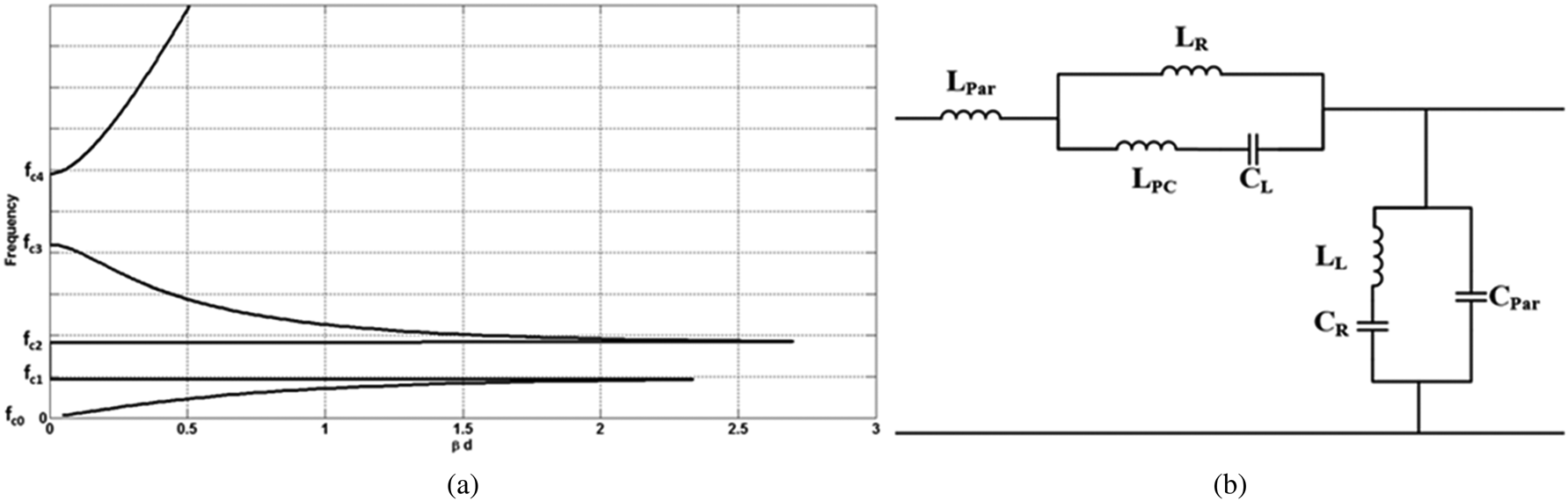
where θ is the hosting transmission line electrical length, Z 0 and Y 0 are the right-handed characteristic impedance and admittance, respectively. An example of dispersion diagram of D-CRLH transmission line is given in Fig. 1(a) where it demonstrates two passbands separated with a sharp stopband in between.
(a) The dispersion diagram of an unbalanced D-CRLH transmission line. (b) The equivalent circuit model for a general D-CRLH unit.

The equivalent circuit of the realized D-CRLH cell is shown in Fig. 1(b). In the equivalent circuit, the elements LR, LL, CR, and CL are representing the distributed loading elements of the hosting microstrip transmission line. To account for any patristic elements of the hosting transmission line that may exist, the elements (Lpar and Cpar) are introduced. Also, the inductor LPC represents the series parasitic inductance of the employed distributed capacitor (CL).
Following the above-discussed equivalent circuit then, the total equivalent series impedance Z, and shunt admittance Y are found to be as follows:


To calculate the cut-off frequencies for the D-CRLH cell and assuming small hosting line length (θ→0), βd in equation (1) should have either π or zero. Then satisfying with equations (2) and (3), equation (1) will be

where A is a constant = (−4) or (0) for βd = π or βd = 0, respectively. The condition βd = π yields the cut-off frequencies (fc 1 and fc 2) whereas the condition, βd = 0, the lower (fc 0) and upper cut-off frequency (fc 3) and (fc 4) in Fig. 1. For example, for βd = 0, the cut-off frequencies can be calculated as


The characteristic impedance for the D-CRLH will be employed in the matching process as

From (6) it can be concluded that the D-CRLH TL does not have constant impedance over the propagation bands. The propagation constant profile in (1) is a non-linear function. Neglecting the effect of parasitic elements (Lpar, LPC, Cpar), the definition for the propagation constant in equation (1) may be further simplified for a short length of hosting transmission line to be as in (7)

Moreover, it is clear that the cut-off frequencies, characteristic impedance, and progressive phase shift are controlled by the values of the loading elements. This will be emphasized in the following sub-section.
Initial design
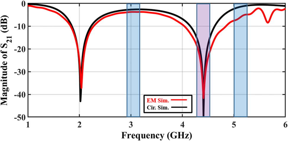
To meet the final proposal, filtering D-CRLH cell is designed to have passbands at 3 and 5.1 GHz with stopband between the two passbands, at 4.1–4.8 GHz. This is applied to design a dual-band self-filtering antenna serving WLAN applications. The equivalent circuit element values that fulfil the desired frequency bands are found to be; Lpar = 1.2, LPC = 2.335, LL = 4.804, LR = 2.0874 (all in nH), CL = 0.2942, CR = 0.1.2872, Cpar = 0.8 (all in pF). The calculated equivalent circuit is simulated using ADS (Advanced Design System) with the results shown in Fig. 2.
Comparison between the equivalent circuit and EM simulation results for the transmission coefficient (S 21) magnitude.

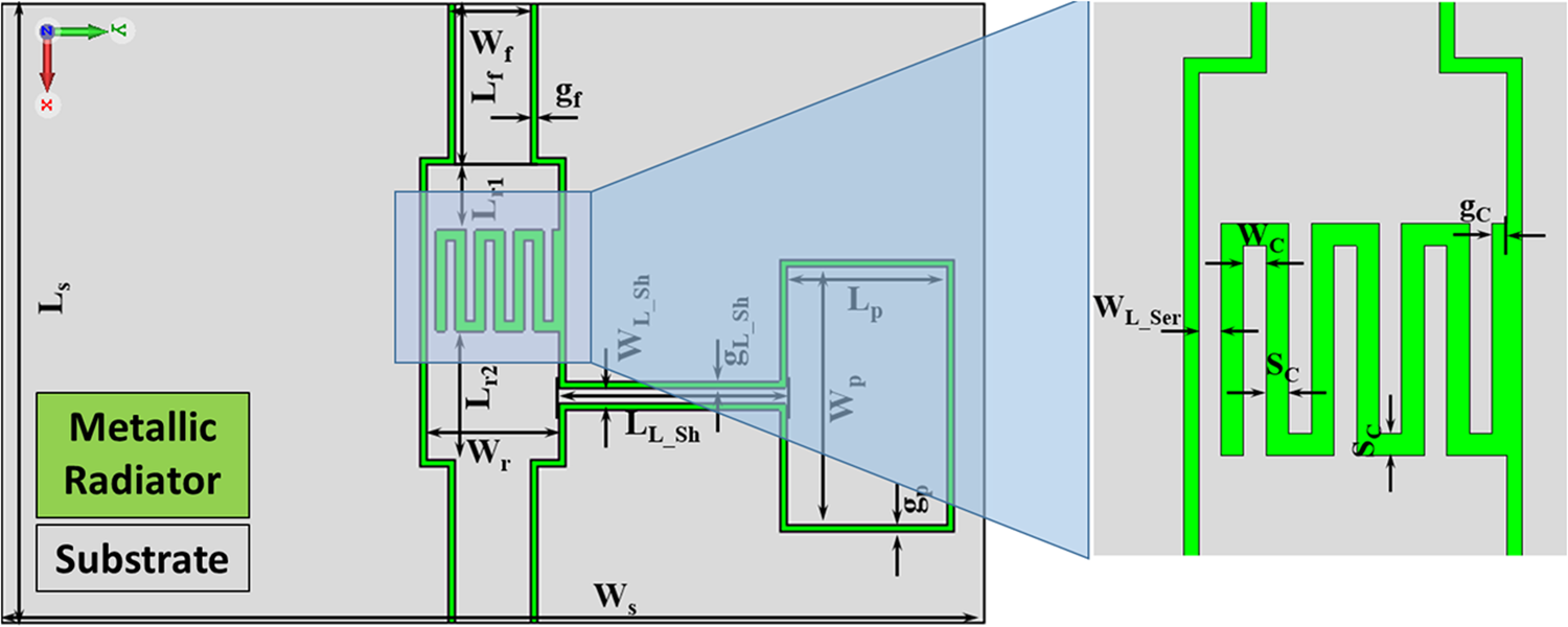
The designed equivalent cell elements are translated to 3D design. Rogers RO4350 substrate with 0.813 mm thickness is selected as a hosting material with coplanar waveguide (CPW) configuration for the cell. As shown in Fig. 3, the D-CRLH cell is realized with a parallel tank circuit formed with a six-finger interdigital capacitor and one series strip inductance. This is represented by the lumped elements LR and CL in Fig. 1(b). Similarly, the thin transmission line's length (LL_SH) and width (WL_SH) are connected to a parallel plate capacitor (Lp) on one side of the CPW grounds. It is worth noting that the green color denotes the metallic cell, while the grey color represents the substrate. This proposed geometry was suggested to achieve high gain for the antenna. These elements are corresponding to the lumped components CR, and LL in Fig. 1(b).
The realized 2D shape of the D-CRLH unit cell.

All equivalent elements are translated to 3D structures based on [Reference Simons and Simons44]. The realized 3D cell is shown in Fig. 3 with detailed dimensions shown in Table 1. The cell is simulated using CST simulation tool and the simulation results are compared to equivalent circuit simulation as in Fig. 2. As shown, there is a passband from around 2.6 to 3.7 GHz and from 4.9 to above 5.9 GHz. The two passbands are separated with a stopband with ranges from 4.1 to 4.8 GHz, insuring filtering specification of the cell. The EM simulation results are compared with the equivalent circuit simulation with a high agreement between them.
The detailed dimensions for the unit-cell

All design parameters are in mm.
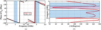
To ensure the correct design steps, the phase of the transmission coefficient (S 21) for both EM and circuit simulations is shown in Fig. 4(a). As shown, the deigned cell has −180 degree at 3 GHz and 180 degree at 5.1 GHz of the transmission coefficient phases for circuit simulations and EM simulations. Finally, the dispersion diagram of the designed filtering cell based on EM simulations is shown in Fig. 4(b). As shown, the dispersion diagram result agree with the magnitude and the phase results of the transmission coefficient as shown in Figs 3 and 4(a), respectively.
(a) Comparison between the equivalent circuit and EM simulation results for the phase of transmission coefficient. (b) The dispersion diagram of the proposed D-CRLH unit cell.

D-CRLH antenna results and analysis
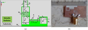
The unit cell discussed in the previous sub-section is modified to the antenna shown in Fig. 5(a), and simulated. The 2D layout of the proposed antenna is shown in Fig. 3. The detailed dimensions are as that used in Table 1, with some minor modification to optimize the antenna results. The fabricated antenna prototype is shown in Fig. 5(b). It is worth noting that the green color denotes the metallic radiator, while the grey color represents the substrate.
(a) The 2D layout of the dual-band D-CRLH antenna. (b) The fabricated D-CRLH antenna.

The dual-band D-CRLH antenna results
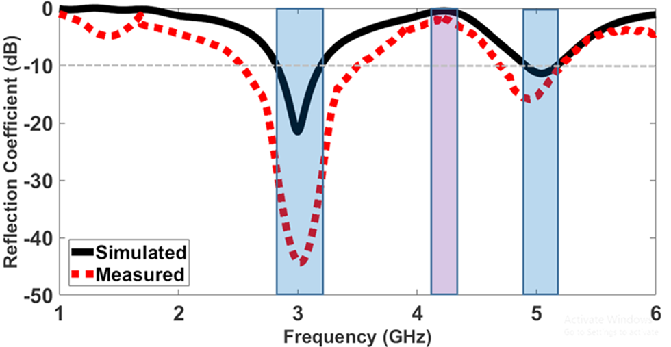
The simulated and measured reflection coefficients of the designed D-CRLH antenna are shown in Fig. 6. As noticed, the prototype exhibits dual-band resonances along with the stopband in-between the resonant bands. The simulated first band ranges from 2.8 to 3.2 GHz (fractional bandwidth of 13.33%) and has a center frequency at 3.0 GHz, at which the reflection coefficient is −22 dB. The measured one is wider and extends from 2.73 to 3.7 GHz (fractional bandwidth of 32.33%) with the center frequency at 3.0 GHz, at which the reflection coefficient is −44 dB.
The simulated and measured reflection coefficients of the dual-band D-CRLH antenna.

On the other hand, the simulated second band ranges from 4.9 to 5.2 GHz (fractional bandwidth of 6%) and has a center frequency at 5.1 GHz, at which the reflection coefficient is −11.4 dB. The measured one is slightly wider and extends from 4.9 to 5.4 GHz (fractional bandwidth of 9.8%) and has a center frequency at 5.1 GHz with the reflection coefficient of −16 dB. Hence, the simulated and measured results confirm the first and second band center frequencies at 3.0 and 5.1 GHz, respectively. Such discrepancies between the simulated and measured results may be claimed due to the fabrication resolution accuracy.
The stopband center frequency, possessing maximum isolation, occurs at 4.25 GHz, which is indicated by the fact that the reflection coefficient is almost 0 dB. Furthermore, the −3 dB bandwidth covers from 3.7 to 4.52 GHz.
Comparing the antenna size, at the two resonant frequencies, to a conventional patch antenna, it can be determined that the conventional patch antenna footprint is 62 × 48 mm2 and 42.4 × 36.4 mm2 at 3.0 and 5.1 GHz, respectively. Hence, the proposed antenna has a very small size which is only 17% at 3.0 GHz and 31% at 5.1 GHz when benchmarked against the conventional patch antenna.
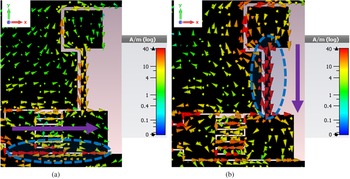
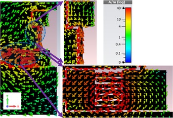
The performance analysis of the designed antenna can be understood by demonstrating the surface current distribution at the resonant frequencies for the same current levels. These simulated results are plotted in Figs 7(a) and 7(b) at 3.0 and 5.1 GHz, respectively. It can be observed that the current is concentrated around the series branch than the shunt branch at 3.0 GHz. However, at 5.1 GHz, the current starts to increase and focus in the shunt branch in comparison to the series branch, as depicted in Figs 7(a) and 7(b), respectively. Furthermore, to confirm the good stopband in-between the two operating bands, the surface current distribution at 4.25 GHz is plotted in Fig. 8, for the same current levels as those in Fig. 7. It can be observed that the current, at the two resonators, follows a complete rotation cycle, which in radiation calculation cancel-out one other. The currents flow in opposite directions; thus, they result in a total bandstop filtering outcome. This observation confirms the almost 0 dB reflection coefficient, signifying total reflection, at that frequency, as was observed in Fig. 6.
The current distribution of the DCRLH antenna at (a) 3.0 GHz, (b) 5.1 GHz.

The current distribution of the D-CRLH antenna at 4.25 GHz, indicating no radiation due to cancellation of currents.

The antenna radiation properties
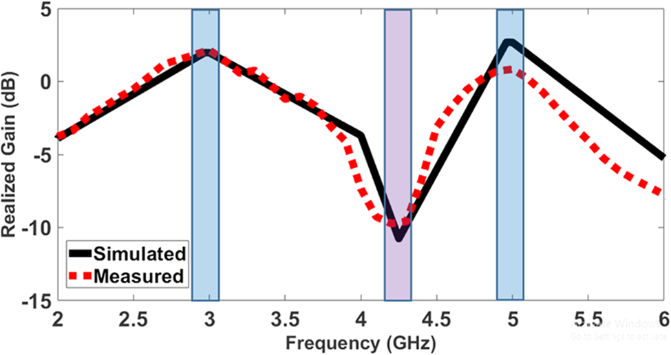
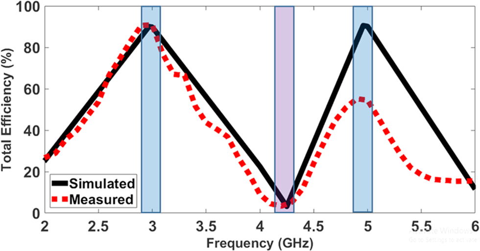
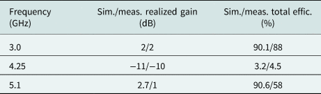
The radiation and filtering properties of the proposed antenna have been emphasized in two main steps. The first one is by depicting the maximum antenna realized gain and antenna total efficiency as a function of frequency, as shown in Figs 9 and 10, respectively. Moreover, tabulated in Table 2 are the simulated and measured realized gains and total efficiencies at the two resonant center frequencies and the stopband mid-frequency.
Comparison between simulated and measured realized gain of the D-CRLH antenna.

Comparison between simulated and measured total efficiency of the D-CRLH antenna.

The proposed D-CRLH antenna simulated and measured realized gain and total efficiency

Now, observing Fig. 9, it is evident that the simulated and measured realized gains highly agree, where the proposed antenna achieves good realized gain of 2 and 2.7 dB at 3.0 and 5.1 GHz, respectively, despite its highly compact size.
Moreover, the proposed antenna measured total efficiency agrees with the simulated one in the low resonant frequency, as portrayed in Fig. 10. However, there is a considerable discrepancy between both efficiency outcomes in the high resonant band.
It is worth to comment that the antenna reflection efficiency er = 10 log (1–|S 11|2) can be calculated from Fig. 6 as follows. At 3 GHz, simulated S 11 is −11 dB and hence er = 92% = −0.36 dB and at 5.1 GHz, S 11 is −21 dB and hence er = 99% = −0.034 dB. Also, without considering the reflection efficiency, the simulated antenna gain values were 2.26 dB at 3 GHz and 3.2 dB at 5.1 GHz. So, this gain increase compensates the difference in reflection efficiency so that the realized gain and total efficiency are almost identical as in Figs 9 and 10, respectively.
In addition, to further justify the stopband at 4.25 GHz, the proposed antenna displayed very low gain and total efficiency values, whether simulated or measured. At 4.25 GHz, it exhibited simulated and measured realized gain values of −11 and −10 dB, respectively, as tabulated in Table 2, demonstrating no radiation. Furthermore, it exhibited simulated and measured total efficiency outcomes of 3.2 and 4.5%, respectively, as tabulated in Table 2.
Illustrated in Fig. 11 is the setup for measuring the proposed antenna normalized gain radiation pattern. Near-field measurements were conducted, where the StarLab Antenna Measurement – MVG was incorporated.
Setup for the D-CRLH antenna radiation pattern measurement.

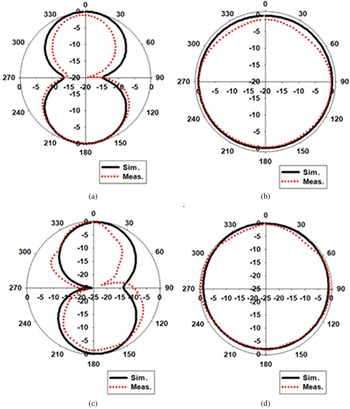
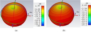
Displayed in Fig. 12 are the normalized polar plots of the gain radiation pattern at both resonant frequencies in the principal planes, where the E-plane denotes the XZ-plane (∅ = 0°), while the H-plane describes the YZ-plane (∅ = 90°). As portrayed in Figs 12(a) and 12(c), the antenna exhibits the figure-of-eight gain radiation pattern at both resonant frequencies in the E-plane, with a high agreement between the simulated and measured polar plots. Similarly, demonstrated in Figs 12(b) and 12(d) are the isotropic gain radiation patterns at 3.0 and 5.1 GHz, respectively, where it is clear that the simulated and measured polar plots highly agree. Hence, the antenna displays the omni-directional radiation pattern type. Next, the 3D gain radiation patterns at 3.0 and 5.1 GHz are portrayed in Figs 13(a) and 13(b), respectively. It is observed that the two radiation patterns are almost typical and exhibit the conventional omni-directional pattern with the same null direction along the Y-axis. This is due to the current cancellation witnessed along the CPW-ground planes.
Comparison between the simulated and measured normalized gain radiation patterns, in polar formats, in the principal planes at: (a) 3.0 GHz (E-plane); (b) 3.0 GHz (H-plane); (c) 5.1 GHz (E-plane); (d) 5.1 GHz (H-plane).

The 3D gain radiation pattern of the D-CRLH antenna at (a) 3.0 GHz, (b) 5.1 GHz.

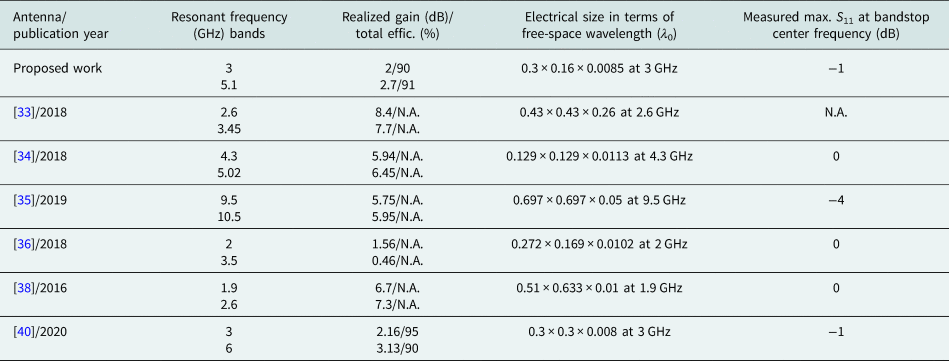
The proposed D-CRLH antenna is benchmarked against other dual-band antennas holding the self-isolation feature, as tabulated in Table 3. The aspects at which comparison was conducted included the antennas resonant frequencies, the antenna electrical size with respect to the free-space wavelength, the peak value of the reflection coefficient at the stopband center frequency, the realized gain, and the total efficiency. It can be seen that the proposed antenna is highly compact and competes with the other references in terms of size. Moreover, it displays a better out-of-band suppression than [Reference Khan and Mandal35], and almost the same as [Reference Dhwaj, Tian and Itoh34, Reference Hu, Pan, Wa and Zhang36, Reference Zhang, Zhang, Pan and Duan38], and [Reference Abdalla, El Atrash, El-Sobky and Zahran40]. Finally, despite its low profile, it exhibits a good realized gain and total efficiency at the two resonant frequencies. Hence, the proposed D-CRLH antenna could be nominated for wireless communication applications.
Comparison between the proposed D-CRLH antenna and dual-band self-filtering antennas

Conclusion
This paper presents a compact dual-band metamaterial-based antenna for wireless applications at 3.0 and 5.1 GHz. The antenna is constructed using only one cell of a D-CRLH transmission line in a simple CPW configuration. The antenna electrical size is only 0.3 λ 0 × 0.16 λ 0 at the low resonant frequency. This is considered a very small size, which is only 17% at 3.0 GHz and 31% at 5.1 GHz, compared to a single-band conventional microstrip patch antenna. Moreover, the antenna displays the monopole-like radiation pattern type with a realized gain of 2 dB at 3.0 GHz and 2.7 dB at 5.1 GHz. Without the integration with a filtering structure, the antenna exhibits a stopband at the center frequency of 4.25 GHz with a realized gain of –11 dB. At 4.25 GHz, this is attained as a result of the current cancellation between the D-CRLH-based resonators. Based on the highly compact size and the presented results, the proposed antenna can serve WiMAX wireless devices.
 Mahmoud A. Abdalla was born in 1973. He received the B.Sc. degree, with a grade of excellent with honors, in electrical engineering from the Electrical Engineering Department, Military Technical College, Cairo, Egypt in 1995. He was awarded the M.Sc. degree in electrical engineering from Military Technical College in 2000, and the Ph.D. degree from microwave and communication group, School of Electrical Engineering, Manchester University, UK, in 2009. He has been with Military Technical College since 1996 where he is a professor and leading the electromagnetic waves group in Electronic Engineering Department. Also, he is a visiting professor in the Department of Computer and Electrical Engineering, University of Waterloo, Canada since 2017. His research has focused on different metamaterial applications in microwave and millimeter bands, especially microwave components, miniaturized multiband antennas, and ferrite components. Also, his research includes electromagnetic energy harvesting systems, EBG components, adaptive antenna systems for DOA estimation and interference cancellations, and radar absorber designs. He has published more than 200 peer-reviewed journal and conference papers. Dr. Abdalla is currently an IEEE senior member, URSI senior member, and a member of the IEEE and the European Microwave Association EuMA. He is an editorial member and reviewer in many electromagnetic journals such as IEEE Antennas and Wireless Propagation Letters, IEEE Transaction in Magnetics, Progress in Electromagnetic Research, European Physical Journal – Applied Physics, Journal of Electromagnetic Waves (JEMW), Advanced Electromagnetic, and International Journal of Microwave and Wireless Technologies. Dr. Mahmoud was the recipient of Egyptian encouragement state prize award for engineering sciences in 2014. In 2019, he was the recipient of Egyptian El-sherouq innovation award in electronic engineering. He was awarded the top 1% Publon worldwide reviewer award for 2018 and 2019. In 2020, he was named in the top 2% scientists in “A standardized citation metrics author database annotated for scientific field/Updated science-wide author databases of standardized citation indicators”.
 Mohamed El Atrash received the B.Sc. degree (with honors) in electrical engineering from the Electrical Systems Engineering Department, October University for Modern Sciences and Arts (MSA), Cairo, Egypt, in 2011. He also received the M.Sc. degree (with distinction) in wireless mobile communication system engineering from the University of Greenwich (UoG), UK, in 2014. In 2020, he successfully completed his Ph.D. degree in electrical engineering at Ain Shams University, Cairo, Egypt. His research interests include flexible wearable antennas, high gain, thin, low profile antennas, and EBG/AMC design. Out of his research, he published articles in the IEEE Transactions on Antennas & Propagation, IET Microwaves, Antennas & Propagation, and the International Journal of Microwave and Wireless Technologies, as well as, a number of conference papers. He is a reviewer in the IET Microwaves, Antennas & Propagation, since 2019, where he has reviewed more than 15 journals. He also reviewed for Microwave and Optical Technology Letters, AEUE-International Journal of Electronics and Communications, and International Journal of RF and Microwave Computer-Aided Engineering.
 Ahmed A. Abdel Aziz received the B.Sc. degree from Avionics Department (with degree Excellent with honor), Military Technical College, Cairo, Egypt in 2014. He joined the avionics research center from 2014 with the main concern about RF and metamaterial-based components. He received the M.Sc. degree in graphene and metamaterial structures for microwave applications from the Electrical Engineering Department, Military Technical College, Cairo, Egypt in 2019. Ahmed's main concern is microwave components, so he is interested in metamaterials, metasurface, and wearable components.
 Mohamed I. Abdelnaser received the B.Sc. degree from Avionics Department (with degree Excellent), Military Technical College, Cairo, Egypt in 2015. He is working in the microwave planning center since 2015. His work is focusing on the development of different microwave and metamaterial-based components and antennas.