I. INTRODUCTION
Potassium dihydrogen phosphate, KH2PO4 (KDP), and its deuterated analogue K(D X H1−X )PO4 (DKDP) are hydrogen bonded crystals. Reference Lines and Glass1,Reference Blinc and Zeks2 Owing to its remarkable photoelectric properties, KDP has been widely used for electro-optic switches and frequency conversion crystals in the large-aperture, high-power laser systems. Reference Yoreo, Burnham and Whitman3,Reference Fedder, Geraghty, Locke, Lane and Wuest4 In such a system, hundreds of large-aperture KDP components of the size of 420 × 420 × 10 mm are needed to meet the requirement of the laser performance. However, a KDP crystal is one of the most difficult-to-cut nonlinear optical materials, because it is soft, deliquescent, easy to fracture, and sensitive to temperature change. As such, it is extremely difficult to make a KDP element with damage-free subsurface and super smooth optical surfaces. Likewise, the laser-induced damage threshold (LIDT), which is the most important property for a KDP element to function in a high-power system, is far below what the intrinsic crystal should have provided. Reference Salo, VAtroschenko, Garnov and Khodeyeva5–Reference Endert and Melle9 It has been suspected that the low LIDT is due to the poor surface integrity of a KDP element caused by a surface machining process, during which damages, such as dislocations, micro/nanocracks, and phase changes, could have been introduced to the KDP crystal. However, the mechanism behind it is not clear.
To improve the laser damage resistance of a machined KDP element, research efforts have been taken to understand the mechanical properties of this type of complex materials subjected to mechanical loading. To date, however, the works are limited to the characterization of KDP's microhardness and Young's modulus in various crystallographic planes and orientations by applying different indentation loads with various tips (e.g., Vickers, Knoop, Spherical, and Berkovich). For instance, Anbukumar et al. Reference Anbukumar, Vasudevan and Ramasamy10 used a Vickers tip to measure the microhardness on the (100) plane of KDP and found that the hardness varied from 1.77 to 1.57 GPa as the indentation load changed from 0.049 to 0.49 N. Fang and Lambropoulos Reference Fang and Lambropoulos11 did the same but in the load range of 0.49–0.98 N. They reported that the hardness varied from 1.7 to 1.4 GPa, which was consistent with the value of 1.43 GPa obtained by Rao and Sirdeshmukh Reference Rao and Sirdeshmukh12 in almost the same load range of 0.5–1.0 N, and that of 1.45 GPa reported by Shaskol'skaya et al. Reference Shaskol'skaya, Hai-kuin and Katrich13 under the load of 1.96 N. These studies showed that the microhardness on the (100) plane of KDP decreases with increasing indentation load.
Wang et al. Reference Wang, Wang and Dong14 examined the (001) plane of KDP and reported that the microhardness varied from 2.75 to 2.2 GPa under the indentation load from 0.005 to 0.009 N. This study indicates that the variation of the microhardness on the (001) plane has a similar dependence on the indentation load, i.e., it decreases with increasing indentation load.
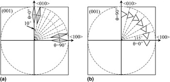
The anisotropic mechanical properties of KDP have been investigated by Fang and Lambropoulos Reference Fang and Lambropoulos11 in further detail using a Knoop tip on the (001) plane with the measurement angle θ varying from 0° to 90° with an increment of 10°, as illustrated in Fig. 1(a). In the test, θ = 0° corresponds to the direction when the indenter's long diagonal coincides with the [010] direction. It was found that the variation of the Knoop hardness was less than 10% in different directions, and that at a low load the microhardness on the (001) plane was about 14% higher than that on the (100) plane. However, this dependence became insignificant at a higher load of about 2 N. Wang et al. Reference Wang, Chen, Dong, Wang, Zhang and Zong16 used a Vickers indenter to investigate the direction effect, with θ varying from 0° to 90° at an incremental step of 10°, under the load in the range of 0.01–1 N. They found that the Young's Modulus E and shear modulus G on the (001) plane of KDP were strongly anisotropic. They also noted that KDP's deformation was fully reversible (or elastic) when the indentation load was below 0.01 N, and that cracking did not occur until 0.02 N. This means that KDP has a microplastic deformation region without cracking. Wang et al. Reference Wang, Chen, Dong, Wang, Zhang and Zong16 further showed that under a load over 0.4 N, cracks would emerge along the indenter corners and edges. However, Fang and Lambropoulos Reference Fang and Lambropoulos11 reported that cracking took place at a much lower load. When the indentation load exceeded 0.25 N, well-formed, straight radial cracks emanated from the corners of an indent on (100) and (001) planes of KDP, together with some lateral cracks. Lu et al. Reference Lu, Gao, Wang, Teng and Wang15 measured the Young's Modulus and nanohardness along different directions on (001) and tripler crystallographic planes, using a Berkovich indenter at the loads of 500–8000 μN. They found that the reduced Young's modulus and nanohardness were dependent on the crystallographic directions and varied periodically along different θ directions as defined in Fig. 1(b). The period of the reduced Young's Modulus and nanohardness were 90° and 120°, respectively, on (001) and tripler crystallographic planes. Such periodic changes were attributed to the effects of crystallographic faces of KDP, geometry of the indenter, as well as the contact stress distribution while indenting in different directions.
Schematic illustration for the anisotropy investigation of KDP according to Refs. Reference Fang and Lambropoulos11 and Reference Lu, Gao, Wang, Teng and Wang15. (a) Knoop indenter, Reference Fang and Lambropoulos11 (b) Berkovich indenter. Reference Lu, Gao, Wang, Teng and Wang15

The mechanical properties of the deuterated KD2X H2(1−X)PO4 crystals were studied by Kucheyev et al. Reference Kucheyev, Siekhaus, Land and Demos17 using a spherical diamond indenter of tip radius ∼1 μm. They reported that the properties were independent of the deuterium degree X (X = 0, 0.3, and 0.6) of the material. However, Shakol'skaya et al. Reference Shaskol'skaya, Hai-kuin and Katrich13 claimed that the deuterium degree did influence the Vickers microhardness which decreased from 1.48 to 1.28 GPa with an increase of X (X = 0, 0.18, 0.50, and 0.95). Kucheyev et al. Reference Kucheyev, Siekhaus, Land and Demos17 proposed that such controversial observations were caused by the difference in crystal growth conditions. In their study, Reference Kucheyev, Siekhaus, Land and Demos17 they also determined the elastic–plastic threshold of DKDP by monitoring the initial pop-in of the indentation curve, and found that this threshold was independent of the deuterium content and loading rate (from 80 to 2500 μN/s). They revealed that slip was the dominant mode of plastic deformation in DKDP. Guin et al. Reference Guin, Katrich, Savinkov and Shaskol'skaya18 investigated the microplastic deformation of KDP. They identified two types of slip systems in KDP using successive polishing and etching, the first of which consisted of slip planes {110}, {101}, {112}, and {123} with a common Burgers vector 〈111〉/2, and the other was identified to be {010}〈100〉. Peng et al. Reference Peng, Zhang and Lu8 investigated KDP properties using a spherical indenter with a tip radius of 1.036 μm at the load of 1000 μN. They found that the pop-in was caused by dislocation nucleation and propagation, that the first pop-in occurred at a stress below that of the major dislocation burst, and that the macroscopic yielding point in KDP was different from the dislocation initiation stress nanoscopically. Their findings indicated that the microdeformation mechanism of KDP is very different from that at a macroscopic scale. Even though the load–displacement curve in nanoindentaion before a visible pop-in is apparently elastic (reversible), slip deformation does happen in this elastic regime. In other words, the true elastic regime of KDP is much smaller than the apparent elastic regime measured by a conventional method.
The discussion above shows that the mechanical properties of KDP have not been well understood. Some results are inconsistent and the micro/nanodeformation mechanisms are unclear. Furthermore, most studies in the literature were based on the ideal tetragonal structure of KDP. No attention has been paid to the possibly significant effect of sample preparation on the testing results. As having been pointed out at the beginning of this section, KDP is a material apt to various damages in surface machining (e.g., in sample preparation). As such, the mechanical properties between an undamaged surface and a machined surface of KDP could be very different. If these critical matters are not clarified, the low LIDT problem in developing the high-power laser systems cannot be solved. The purpose of the present paper is to elucidate some of these issues.
II. EXPERIMENT
The samples used in this investigation were as-grown KDP crystals produced by the State Key Laboratory of Crystal Materials, Shandong University (Jinan, China), using a rapid growth method as described in details elsewhere. Reference Fu, Gao, Sun, Wang, Li, Zeng, Luo, Duan and Wang19 The crystallographic orientation of the samples was (210) with orientation errors less than 0.5°, which was confirmed by an x-ray diffraction analysis on the Philips PANalytical MRD diffractometer (Almelo, The Netherlands).
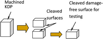
The KDP samples were finished by a diamond fly cutting machine (HIT-2, developed in-house in Harbin Institute of Technology, Harbin, China). The sample surface roughness R a was less than 5 nm, measured on a Wyko RST-plus (Veeco Metrology Group, Santa Barbara, California) with the scan area of 1 mm × 1 mm. To identify the effect of surface machining on the mechanical properties of KDP, samples with machined surface and damage-free surface (as-grown, or called original surface) are both required. To obtain a sample with an original surface, a mechanical stress cleavage method was used. This method, as illustrated in Fig. 2, has two steps. First, a machined KDP block was sectioned to a small piece perpendicular to the machined surface. This piece was then cleaved in parallel to the machined surface to break it into two parts, exposing the damage-free surface.
Schematics of the preparation procedure of damage-free (original) KDP surfaces.

The nanoindentation tests were conducted on a Hysitron TI950 Triboindenter (Eden Prairie, Minnesota). A standard Berkovich tip was used, which had an included angle of 142.35° (the angle from one edge to the opposite side) and radius of curvature of ∼150 nm. The area function of the indenter tip was accurately calibrated by a standard material, fused quartz. Reference Bei, George, Hay and Pharr20 Peak indentation forces of 100–8000 μN were applied and the same rates ranging from 20 to 4000 μN/s were used for both loading and unloading. To investigate the effect of indentation holding time (HT) on the microdeformation of KDP, four holding periods, i.e., 5, 10, 30, 60 s, were applied at the peak force for each indentation test. The indentation topography was characterized by an in situ scanning probe microscope (SPM) function of the nanoindentation device. For each condition, more than 10 tests were carried out to ensure that the results were repeatable and reliable.
To understand the effect of residual stresses on the postindentation deformation of KDP, a series of topography examinations of the indented KDP surfaces were carried out, on both the indented original and machined surfaces. In situ SPM imaging scans were conducted immediately after an indentation, and then again in 5 h, 24 h, and a month.
III. RESULTS AND DISCUSSION
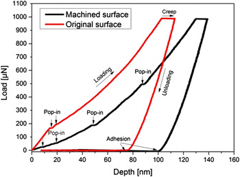
Figure 3 shows typical load–displacement curves of the indentation tests on the machined and original surfaces. For both cases, the peak forces were 1000 μN, the loading/unloading rates were 200 μN/s, and the HTs were 5 s. Both plots show that the pop-in events occur at different locations of the loading paths, yet no pop-out or elbow events appear during unloading. Moreover, adhesion between tip and sample also emerged at the end of unloading.
Typical load–displacement curves of nanoindentation tests on the machined and original surfaces.

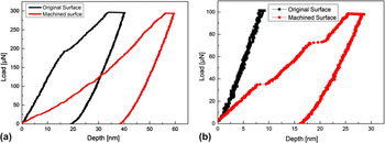
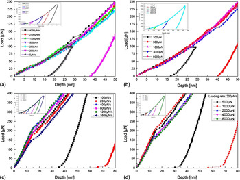
However, the slopes of these two curves are significantly different, especially at the beginning of indentation. In other words, the mechanical properties of KDP after machining were changed. To further understand this difference, additional indentation tests with low peak forces (300 and 100 μN) were carried out on both the machined and original surfaces. As shown in Fig. 4(a), the first pop-in (critical transition load) of the original surface took place at the load of about 190 μN. However, on the machined surface, this happened at about 35 μN. With a lower peak force of 100 μN [see Fig. 4(b)], the loading and unloading curves of the original surface overlapped, indicating that the deformation is reversible and elastic. This is because the critical stress for the onset of plastic deformation has not been reached. In contrast, several pop-in events appeared at very low loads when the machined surface was indented. This indicates that surface machining has somehow altered the mechanical properties of the KDP.
Indentation tests on the machined and original surfaces with peak forces of (a) 300 μN, and (b) 100 μN.

The influences of the peak force and loading rate on the critical transition load were investigated on both the machined and original surfaces of KDP, using the same Berkovich indentation tip. As shown in Fig. 5, the critical transition loads of the machined surface (25–40 μN) and the original surface (150–220 μN) were nearly independent of peak force and loading rate. This is qualitatively consistent with that reported by Kucheyev et al. Reference Kucheyev, Siekhaus, Land and Demos17 although the loading rates used by them varied from 80 to 2500 μN/s. However, the values of the first pop-in are different. According to Kucheyev et al., Reference Kucheyev, Siekhaus, Land and Demos17 the first pop-in occurred at the loads of 566 ± 87 and 225 ± 52 μN, respectively, on the (001) and (100) surfaces. The difference can be attributed to several factors such as the anisotropy of the KDP crystals, the indenter shapes (this study used a Berkovich indenter, but Kucheyev et al. Reference Kucheyev, Siekhaus, Land and Demos17 used a spherical indenter), and the sample preparation method. This once again shows that the deformation of KDP is sensitive to loading conditions.
Effects of peak force and loading rate on the critical transition load of the machined and original surfaces. All figures are magnified views of the low loads from their complete indentation curves (insets). Indenting on the machined surface at different peak forces using (a) different loading rates and (b) a constant loading rate of 200 μN/s; indenting on the original surfaces at different peak forces using (c) different loading rates, and (d) a constant loading rate of 200 μN/s.

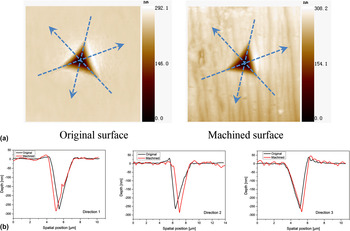
Figure 6 shows the typical microtopographies of the machined and original surfaces after nanoindentation. It can be seen that the machined surface was rougher [Fig. 6(a)], and its indentation imprint depth was larger [Fig. 6(b)] than that of the original surface. It should be noted that the indentation depth was much greater than the surface roughness (<5 nm), and the influence of roughness would be only at the initial stage of the indentation. Reference Kim, Kang and Lee21 Therefore, the alteration of the mechanical properties of KDP on the machined surface should be attributed to the sample preparation, where dislocations Reference Peng, Zhang and Lu8 and defects Reference Kiely, Hwang and Houston22 can be introduced in the subsurface and thus leading to easier macroscopic plastic deformation. Reference Goken and Kempf23,Reference Wang, Bei, George and Pharr24 It was reported that the dislocation density before machining was ∼103 cm−2 (Ref. Reference Endert and Melle9), and it became greater than 104 cm−2 after machining. Reference Wu, Chao, Wang, Wang, Gao and Kang25 Thus the subsurface damage after machining will affect the mechanical properties of KDP. This kind of subsurface damage will certainly downgrade the optical performance (e.g., LIDT) of the KDP.
Indentation topographies of the original and machined KDP surfaces after nanoindentation. (a) SPM images and (b) imprint depth profiles in different directions [as shown in (a)]. The peak force was 8000 μN and the durations for loading, holding, and unloading were 5 s.

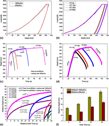
Figure 7 shows the effect of the loading rate and HT on indenting the original surface of KDP. It is obvious that regardless of the indentation conditions, creep occurs when the indenter was held at the peak force. There are two possible sources for the creep. One is the drift of the nanoindenter system, and the other is the actual creep deformation of KDP. It has been proved that the system drift induced by noise was very small at the open-loop mode, i.e., around 0.05 nm/s. With this, a displacement drift caused by noise should be smaller than 0.25 nm with the HT of 5 s, which is negligible compared with the large displacement variation detected at the maximum load [Fig. 7(f)]. It is noted that the creep deformation on machined surfaces varies in a similar way but with different magnitudes. It is therefore evident that KDP experienced significant creep deformation, similar to some other materials such as metals Reference Liu, Liua, Zhao and Northwood26 and polymers. Reference Yang, Zhang and Zeng27 At the same time, the homologous temperature of KDP is T/T m = 300 K/526 K ∼ 0.57, i.e., it falls into the creep region. Therefore, it is understandable for KDP to activate creep deformation under a high stress at room temperature (RT).
Creep deformation of KDP crystals when indenting on original surfaces. (a) Creep deformation under different loading rates, (b) creep deformation with different HT under the same loading rate and peak force (loading/unloading rate = 1600 μN/s, peak force = 8000 μN). Indentation depth variation with HT under loading rate of (c) 1600 μN/s and (d) 200 μN/s, (e) effect of loading rate and HT on creep deformation, (f) variation of the maximum creep deformation depth with different loading rates and HTs.

Figures 7(c)–7(f) show that KDP's creep deformation is significantly influenced by loading rate. Figures 7(e) and 7(f) show that the HT effect on creep deformation gets greater under higher loading rates. The creep deformation rate δ = dh/dt h, at the maximum load, changes in a similar way, where dh is the relative displacement variation within a period of dt h, but the variation is nonlinear, as shown in Figs. 7(c)–7(f).
It is well known that creep deformation in metals or alloys is highly temperature and time dependent. At a high temperature, the creep deformation is commonly attributed to atomic diffusion (e.g., Nabarro-Herring creep and Coble creep) Reference González-Doncell and Sherby28 related to grain size. At a low temperature, on the other hand, the creep deformation is stress-dependent, and occurs only after yielding. Reference Wang and Chen29 In this context, dislocation activities (e.g., slip or climb) play an important role in the creep deformation. In the nanoindentation process, the KDP is subjected to a very high stress, which inevitably results in plastic deformation in the crystal within a local zone. In this zone, the mechanism of dislocation glide would dominate the creep process. Reference Li, Henshall, Hooper and Easterling30–Reference Wang, Zhang and Chen32
Furthermore, the creep deformation is strain rate dependent and has a power-law variation tendency, which can be elucidated by the theory of mobile dislocation density. Reference Alden31 First, a higher strain rate requires a shorter deformation time and consequently a higher dislocation mobile velocity. Since dislocation mobile velocity is a function of effective stress, a higher stress is thus required to sustain the strain rate. Reference Li, Henshall, Hooper and Easterling30,Reference Alden31 This also explains why the initial indentation depth under a higher strain rate is always smaller than that under a lower strain rate at the same peak force. Secondly, the multiplication rate of a new mobile dislocation depends on the stress increasing rate (i.e., loading rate). Reference Li, Henshall, Hooper and Easterling30 In other words, the density of mobile dislocation under a higher strain rate would be higher than that under a lower strain rate. Thus, under a higher loading rate, the initial creep deformation rate of the holding stage is higher. With increasing the HT, the density of mobile dislocations decreases rapidly as the mobile dislocations are trapped by the dislocation networks, which would subsequently reduce the size of the mobile dislocations. This explains why the creep deformation velocity drops at the tendency of a power-law. It is noted that the maximum creep deformation under a higher strain rate is considerably larger than that under a lower strain rate (see Fig. 7). This is because the density of the mobile dislocations of the former is higher, such that the materials in the localized zone could undergo severer deformation. Moreover, the stress at the beginning of the holding stage under a higher strain rate is higher too, resulting in a larger creep deformation within the zone.
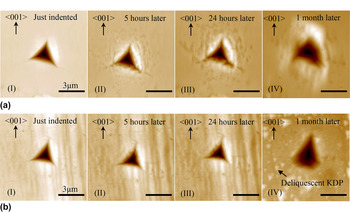
It is interesting to note that KDP experienced a postindentation deformation under the residual stress produced by indentation. As shown in Fig. 8, both the topographies of the original and machined surfaces after indentation show gradual, time-dependent evolutions. The whole process can last more than 1 mo. Within the first few hours, on the original surface, the deformed material around the indent expanded externally, accompanying with the roughening of the surface in the vicinity of the indentation mark, as shown in Fig. 8(a). With increasing time, the material piled up around the edge of the indentation mark, and the surface topography became nonuniform. It is worth noting that the pile-up of the material preferably accumulated along the crystalline direction 〈001〉, as shown in Fig. 8(a) (IV), indicating that the KDP deforms more easily along certain crystalline directions under the residual stresses. This could be related to the anisotropy of the KDP crystal.
Variation of postindentation deformation with time. (a) original surface, (b) machined surface. The peak forces were 8000 µN and the loading/unloading rates were 1,600 µN/s.

The postindentation deformation on a machined surface [Fig. 8(b)] is quite different from that of the original surface. Initially, the postindentation deformation rate of the machined surface was slower (i.e., within 24 h), which however, changed very significantly after a month, as shown in Fig. 8(b) (IV). This discrepancy could be attributed to the different initial residual stresses before indentation. The original surface was damage-free, and hence was free from initial residual stresses; whereas, the machined surface/subsurface had process-induced damages and residual stresses prior to indentation. Such pre-existing residual stresses in the machined surface may affect the postindentation deformation. It is interesting to note that the moisture invasion could also significantly affect the postindentation deformation. As shown in Fig. 8(b) (IV), the entire surface of the machined surface became deliquescent after a month from indentation, evidenced by the deliquescent materials distributed around the indentation imprint. It is noted that the deliquescence influenced the relaxation process due to the change of the environmental condition, when the machined samples were moved from one testing chamber to the other. However, this was not the case for a sample with original surfaces Fig. 8(a) (IV). The deliquescent process may also contribute to the postindentation deformation of the machined surface. Moreover, our recent study revealed that KDP deformation is dominated by hydrogen dynamics, Reference Mylvaganam, Zhang and Zhang33 suggesting that the hydrogen bonds in the microstructure of KDP could also play a significant role in the postindentation deformation.
All the above results show that KDP crystals are a visco-elasto-plastic material during micro/nanoscale deformation, although the material is very brittle macroscopically.
IV. CONCLUSIONS
This paper has investigated the deformation behavior of KDP crystals before and after machining with the aid of nanoindentation. It was found that the first pop-in event is independent of the loading rate and maximum indentation load. However, surface machining can significantly change the mechanical properties of KDP, by the machining-induced subsurface damages and residual stresses. Pronounced creep deformations were discovered on both original and machined surfaces, which were highly depended on the stress and strain rate applied. Dislocations activities, i.e., dislocations glide plasticity, are the main source of creep deformation. It was noted that an indented KDP experienced considerable postindentation deformation over a period of a month. Such postindentation deformation process is affected by the anisotropy of the material, the extent of the surface/subsurface damages it contains, the initial residual stresses, and the atmospheric condition. It is clear that a KDP crystal can undergo very complicated visco-elasto-plastic deformation at a micro/nanoscale, although it is very brittle at a macroscale.
ACKNOWLEDGMENTS
The authors are grateful to Dr. Yu Wang at the University of New South Wales for his invaluable comments and suggestions. This work was financially sponsored by NSFC (Grant No. 51375122).