
1. Introduction
The dynamical features of blunt bluff body wakes exhibit the same key aerodynamic features as several types of road vehicle. Exploring their flow characteristics and the effect on aerodynamic drag is of immense importance as the aerodynamic drag is linked to fuel consumption and, for electric vehicles, driving range. The turbulent wake past a blunt (square-back) bluff body in close proximity to the ground exhibits dynamical modes which result from the interaction between the separated shear layers in the wake region downstream of the body. They include Kármán vortex shedding in both cross-flow directions, streamwise bubble pumping, bi-modal wake switching and mixing layer dynamics, as well as more complex interactions between these. Both experimental (Grandemange, Gohlke & Cadot Reference Grandemange, Gohlke and Cadot2013b; Haffner et al. Reference Haffner, Borée, Spohn and Castelain2020) and numerical studies using direct numerical simulation (Podvin et al. Reference Podvin, Pellerin, Fraigneau, Evrard and Cadot2020), large eddy simulations (LES) (Hesse & Morgans Reference Hesse and Morgans2021; Ahmed & Morgans Reference Ahmed and Morgans2022) and improved delayed detached eddy simulations (IDDES) (Fan et al. Reference Fan, Xia, Chu, Yang and Cadot2020; Kang et al. Reference Kang, Essel, Roussinova and Balachandar2021) capture most of these modes.
Kármán vortex shedding arises from the interaction between parallel shear layers. The cross-section of the square-back Ahmed body promotes Kármán vortex shedding in both cross-flow directions, as two pairs of shear layers (top–bottom and side–side) separate at the base. The Kármán vortex shedding is oscillatory, with the characteristic time in both directions found to be around  $5 H/ U_{ \infty }$, where
 $H$ is the body height and
 $U_{\infty }$ is the free-stream velocity (Grandemange, Gohlke & Cadot Reference Grandemange, Gohlke and Cadot2013a), with the typical dimensionless frequency (
 ${St}_{n}$) being
 ${St}_{n} = f n/U_{\infty } = 0.12\unicode{x2013}0.2$, where
 $f$ is the frequency and
 $n$ is the distance between the shear layers. The low-frequency streamwise pumping motion of the recirculation region – the so-called bubble pumping – occurs at a frequency of
 $St_{H} \sim 0.04\unicode{x2013}0.06$ based on the body height
 $H$. Although this mode is captured in the wake of other bluff bodies, including an axisymmetric body (Rigas et al. Reference Rigas, Oxlade, Morgans and Morrison2014), a circular disc and a sphere (Berger, Scholz & Schumm Reference Berger, Scholz and Schumm1990), understanding of its physical mechanism remains incomplete. Duell & George (Reference Duell and George1999) suggested that it is related to the momentum exchanged between the recirculation region and the free shear layers encompassing it, while Volpe, Devinant & Kourta (Reference Volpe, Devinant and Kourta2015) suggested that it is related to a nonlinear interaction between the vertical and horizontal vortex shedding. The dynamics of the free shear layers (mixing layers) is found to be related to the instantaneous spatial location of the recirculation region, which is directly linked to wake bi-modality. Vortex roll up at a relatively higher frequency of
 $St_{H} \sim 1$ is reported from one of the parallel shear layers, occurring interchangeably between them in a manner that follows the position of the recirculation region (Haffner et al. Reference Haffner, Borée, Spohn and Castelain2020; Ahmed & Morgans Reference Ahmed and Morgans2022).
Wake bi-modality, also known as bi-stability, is defined as a random switching of the centre of the wake between two asymmetric reflectional positions. The wake configuration exhibits the same symmetry breaking that first occurs in the laminar flow regime (Rigas et al. Reference Rigas, Morgans, Brackston and Morrison2015), with the effect of turbulent fluctuations leading to switching between the states of broken symmetry. The experimental study by Grandemange, Cadot & Gohlke (Reference Grandemange, Cadot and Gohlke2012) found that the wake loses its spatial symmetry at  $Re_{H} = \frac{U_{\infty} H}{\nu}$ (where
 $H$ is the body height) and locks into at one of two equiprobable asymmetric positions. This occurs due to a sequence of pitchfork bifurcations changing the state of the wake from steady symmetric to steady asymmetric. Increasing the Reynolds number further in the laminar flow regime introduces unsteadiness into the asymmetric wake. The wake then loses its temporal symmetry due to a Hopf bifurcation, leading to Kármán vortex shedding. Evstafyeva, Morgans & Dalla Longa (Reference Evstafyeva, Morgans and Dalla Longa2017) captured the same sequence of bifurcations numerically. In the turbulent flow regime, reflectional symmetry breaking is preserved. The turbulent fluctuations force the wake to switch between the reflectional asymmetric positions stochastically, with the wake recovering symmetry in the long time average. The characteristic time of this behaviour is found to be 2 to 3 orders of magnitude higher than the Kármán vortex shedding. Bi-modality is found to be a unidirectional behaviour, occurring in one of the cross-flow directions. This switching direction depends on the underbody flow (i.e. ground proximity), the aspect ratio of the body cross-section and the yaw angle (Grandemange et al. Reference Grandemange, Gohlke and Cadot2013a). For a given aspect ratio of the body base, the wake tends to switch in the direction of the longest edge (Grandemange et al. Reference Grandemange, Gohlke and Cadot2013a). Similar symmetry breaking behaviour is observed in the wake of axisymmetric bodies, where the wake exhibits multi-modality across different azimuthal positions. Compared with axisymmetric bodies, the geometrical symmetry of the base surface of the square-back Ahmed body permits only two azimuthal wake positions, promoting bi-modality instead of multi-modality. The contribution of wake bi-modality to pressure drag is found to be approximately
 $10\,\%$ based on the mean base pressure (Haffner et al. Reference Haffner, Borée, Spohn and Castelain2020).
Bi-modality has been found to be sensitive to the underbody flow emanating from the clearance between the body and the ground (Grandemange et al. Reference Grandemange, Gohlke and Cadot2013b; Barros et al. Reference Barros, Borée, Cadot, Spohn and Noack2017), the free-stream turbulence level (Cadot et al. Reference Cadot, Almarzooqi, Legeai, Parezanović and Pastur2020; Burton et al. Reference Burton, Wang, Smith, Scott, Crouch and Thompson2021; Kang et al. Reference Kang, Essel, Roussinova and Balachandar2021) and the dynamics of the boundary layers which form along the longitudinal surfaces of the body (Hesse & Morgans Reference Hesse and Morgans2021).
The experimental study by Barros et al. (Reference Barros, Borée, Cadot, Spohn and Noack2017) investigated the effect of disturbing the underbody flow on the wake configuration. Disturbances were introduced using passive devices in the clearance between the body and the ground upstream of the base, which disturb the boundary layer developing along the bottom surface, affecting the rate of entrainment in the wake. These included quasi-two-dimensional disturbances using a horizontal cylinder extending along the spanwise direction, three-dimensional disturbances employing vertical cylinders and using an underbody grid. The size of the disturbing device and the resulting forcing frequency were found to be important for changing the wake configuration to bi-modal states. High-frequency forcing changed the state of the wake from a vertically asymmetric uni-modal wake to a horizontally (spanwise) bi-modal switching wake, while relatively low-frequency forcing switched the vertically balance of the wake, without introducing bi-modal switching in the vertical direction.
Recent studies have shown that the free-stream turbulence level has a prominent effect on wake bi-modal switching, both by directly affecting the wake dynamics and indirectly affecting it via the underbody flow. Kang et al. (Reference Kang, Essel, Roussinova and Balachandar2021) numerically investigated the effect of the approach flow conditions using IDDES. They concluded that, when the wake is fully submerged in a thick turbulent boundary layer whose height exceeds the body height, bi-modality is completely suppressed. This change in the flow topology and near-wake dynamics is attributed to the momentum deficit in the underbody flow, with bi-modality suppression suggested to be linked to the induced upwash flow.
An experimental investigation by Cadot et al. (Reference Cadot, Almarzooqi, Legeai, Parezanović and Pastur2020) found that increasing the turbulence intensity ( $\sim$5 %) of the free-stream flow increases the wake residence time at each asymmetric position, reducing the frequency of wake switching events. They suggested that the higher turbulence intensity thickens the free shear layers in the wake, leading to a reduction in the turbulent local oscillations of the wake around its asymmetric position. A different experimental study by Burton et al. (Reference Burton, Wang, Smith, Scott, Crouch and Thompson2021), however, showed that bi-modality persists across a range of free-stream turbulence intensities (
 $1\,\% \sim 15\,\%$). Higher turbulence intensities increase wake meandering and disturb the stability at a given asymmetric position, which accordingly significantly increases the occurrence of wake switching events. They attributed this behaviour to the free-stream turbulence changing the momentum distribution in the switching direction, interrupting the wake directly or indirectly by affecting the boundary and separating shear layers. Thus, the effect of changing the free-stream turbulence levels on the switching mechanism remains inconclusive and warrants further investigations.
The effect of boundary layer disturbances on wake bi-modality was the focus of a numerical study by Hesse & Morgans (Reference Hesse and Morgans2021). Using wall-resolved LES, they observed a link between the dynamics of the upstream boundary layers along the body surfaces and wake bi-modality. The boundary layers on the top and side surfaces of the Ahmed body separate just after the body nose, reattaching a short distance downstream before evolving as they move towards the base. They showed that these disturbances have a prominent effect in triggering bi-modal switching of the wake. This motivates our current work aiming to investigate the effect of the upstream boundary layer dynamics on bi-modality.
The objective of this study is to investigate the effect of the separation and reattachment of the upstream body boundary layers, along with the associated boundary layer disturbances, on the wake bi-modality. This is with a view to informing future control strategies for drag reduction. Large eddy simulations will be used to investigate the effect of applying suction and momentum to suppress the boundary layer dynamics. The simulation set-up is discussed in § 2 followed by a brief analysis of the unforced flow in § 3. The effect of suppressing the upstream boundary layer dynamics on both the time-averaged and time-resolved quantities is explored in § 4. Conclusions from the work are drawn in § 5.
2. Simulation set-up
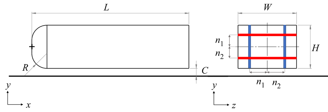
In this study, LES are used to investigate the flow past a three-dimensional blunt bluff body. The geometry considered here is the standard square-back Ahmed body of Ahmed, Ramm & Faltin (Reference Ahmed, Ramm and Faltin1984) scaled down to one fourth. The set-up and dimensions are similar to those in Ahmed & Morgans (Reference Ahmed and Morgans2022). The lengths of the body in the streamwise ( $x$), spanwise (
 $z$) and transverse (
 $y$) directions are
 $L$,
 $W$ and
 $H$, respectively. The coordinate system is set to
 $(0,0,0)$ at the centre of the body fore end. The vertical distance between the bottom surface and the ground is
 $C$. The fore end of the body is rounded with a radius
 $R$. These dimensions are normalised by the width of the body
 $W$ and denoted as
 $(.)^*$, as shown in figure 1. The values of the normalised dimensions are
 $L^*=2.49$,
 $H^*=0.74$,
 $C^*=0.13$ and
 $R^*=0.26$, with the body width
 $W$ being
 $97.25$ mm.
Square-back Ahmed body scaled by one fourth, with width  $W = 97.25$ mm (drawing scale 1 : 2). Pressure sensors on the base are marked by the blue and red lines in the vertical (
 $y$) and the horizontal (
 $z$) directions, respectively. Point
 $(0,0,0)$ is positioned at the centre of the front surface indicated with the black
 $+$.

The size of the virtual wind tunnel test section i.e. the solution domain, is chosen according to ERCOFTAC recommendations (European Research Community On Flow, Turbulence and Combustion; Jakirlic, Jester-Zürker & Tropea Reference Jakirlic, Jester-Zürker and Tropea2001; Manceau Reference Manceau2003). The dimensions of the solution domain are  $(L_{inlet},L_{x},L_{y},L_{z}) = (2L,8L,6.7H,5W)$, where
 $L_{inlet},L_{x},L_{y}$ and
 $L_{z}$ are the domain length upstream of the body, the total domain length in the streamwise direction, the transverse domain length and the domain length in the spanwise direction, respectively. This size leads to a blockage ratio of
 $2.5\,\%$, defined as the ratio of the body cross-section to the domain cross-section, which is low enough to avoid significant confinement effects.
The Reynolds number based on the body width is  $Re_{W}=4.46 \times 10^4$. The flow is introduced into the domain with a uniform velocity corresponding to
 $Re_{W}$ at the inlet surface. A no-slip condition is applied on the body surfaces and the ground, and a free-slip condition on the side and top surfaces of the solution domain. The outlet of the domain is set to be a convective outlet to avoid back flow. A finite volume solver using the OpenFOAM computational fluid dynamics toolbox is used to solve the discretised governing equations. The unsteady incompressible Navier–Stokes equations are solved using the PIMPLE (Pressure IMplicit with splitting of operator for Pressure-Linked Equations; Barton Reference Barton1998) algorithm, which combines the PISO (Pressure-Implicit with Splitting of Operators; Issa Reference Issa1986) and SIMPLE (Semi-Implicit Method for Pressure-Linked Equations; Patankar & Spalding Reference Patankar and Spalding1972) algorithms. Both the spatial and temporal terms of the governing equations are discretised using second-order schemes. The solution domain is discretised using unstructured hexahedral cells with prism layers to fully resolve the boundary layers (the viscous sub-layer) on the solid surfaces with a value of
 $y^+ \sim 1$. Turbulence at subgrid-scale levels is modelled using the wall-adapting local eddy-viscosity model (Nicoud & Ducros Reference Nicoud and Ducros1999). The final mesh size, chosen according to the mesh independence study shown in Ahmed & Morgans (Reference Ahmed and Morgans2022), is
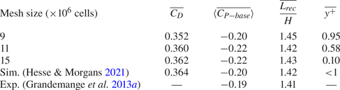
 $11$ million cells, with the comparison parameters being the drag coefficient and the length of the recirculation region downstream of the body. The nominal cell size in the wake is chosen to resolve the Taylor microscale, which represents the minimum turbulent length scale to be resolved by the LES (Howard & Pourquie Reference Howard and Pourquie2002). Details on the mesh independence study are shown in Appendix A.
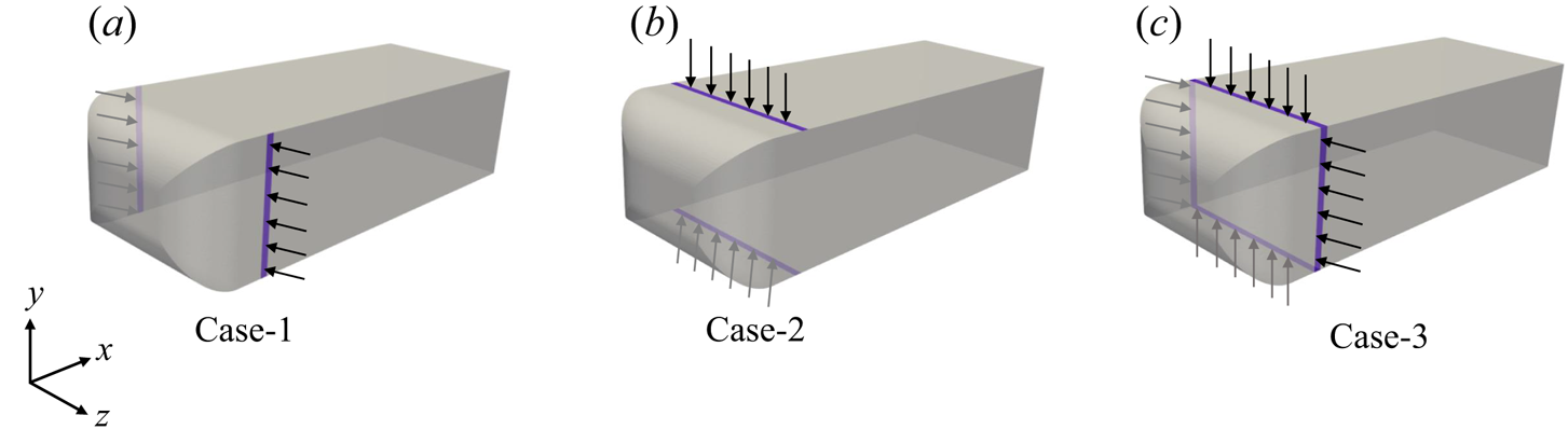
The purpose of the present study is to investigate the effect of disturbances emanating from the boundary layer separation and reattachment just aft of the nose, by using steady suction to suppress the boundary layer separation. While the details of the nose separation may depend on  $Re$, investigating this is beyond the scope of the current study. A steady suction slot is applied on the body surface at a streamwise position of
 $0.15 L$ from the fore end of the body on all the longitudinal surfaces of the body, as shown in figure 2. The streamwise location of the suction corresponds to just after the boundary layer separation line as determined in the unforced case. The suction velocity is
 $U_{s}$, normal to the surface, and the actuator slots have a width (i.e. streamwise extent) of
 $0.03 W$. The value of
 $U_{s}$ is spatially independent.
Different suction configurations for suppressing separation of the body boundary layers. Purple slots indicate the actuator locations which have a slot width (streamwise extent) of  $3\,\%$ of the body width. Black arrows indicate suction.

A set of simulations were performed in which different values of  $U_{s}$ ranging from
 $0.1~U_{\infty }$ to
 $1.0~U_{\infty }$ were applied. The most effective value for fully suppressing the boundary layer disturbances was
 $U_{s} = 1.0~U_{\infty }$, hence this was the value chosen for the following investigations. Different forcing (suction) configurations were then chosen, all of which yielded zero net side and vertical forcing, this being essential to avoid any expected shift to the horizontal and vertical balance of the wake due to forcing alone. Three cases were considered, with the forcing set-up summarised in table 1. For case-1, suction is applied on the body side surfaces only. For case-2, suction is applied on both the top and bottom surfaces only, with none on the side surfaces. For case-3, all four surfaces have suction applied. Figure 2 depicts a schematic of the three cases.
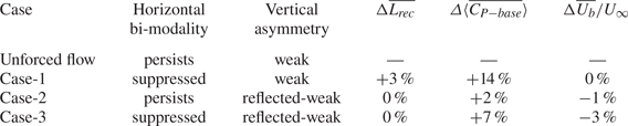
Summary of the suction forcing on the longitudinal body surfaces for the different cases.

The pressure coefficients used in analysing the data in the following sections are calculated as shown in (2.1). Here,  $P(x,y,z,t)$,
 $P_{\infty }$,
 $\rho$ and
 $U_{\infty }$ represent the pressure at a position
 $(x,y,z)$ in space at an instant
 $t$, the free-stream pressure, the air density and the free-stream velocity, respectively,
 \begin{equation} C_{P}(x,y,z,t)= \frac{P(x,y,z,t)-P_{\infty}}{\frac{1}{2} \rho {U_\infty}^2}. \end{equation}
The spatial gradient of the coefficient of pressure ( $C_P$) in a direction
 $\boldsymbol {n}$ is calculated as shown in (2.2), where
 $\boldsymbol {n}$ represents a cross-flow direction (
 $y$,
 $z$),
 $d_{n1}$ and
 $d_{n2}$ are the distances between the respective base pressure probes (one set either side of the base centre line in each direction) and the centre of the base in the direction
 $n$,
 $M$ is the number of probes and
 $N$ is the base length in the same direction, as shown in figure 1. In the following analysis,
 $\bar {A}$ represents the time-averaged value of
 $A$ and
 $\langle A\rangle$ denotes the area-averaged value of
 $A$
 \begin{equation} \frac{\partial
C_P(t)}{\partial n}= \frac{\mathop{\displaystyle\sum\limits_{M}} {C_P(n_1,t)}-\mathop{\displaystyle\sum\limits_{M}}
{C_P(n_2,t)}}{\dfrac{M(d_{n1}+d_{n2})}{N}} .
\end{equation}
3. Unforced flow
The unforced case considered here is identical to the one used in Ahmed & Morgans (Reference Ahmed and Morgans2022). The wake configuration downstream of the Ahmed body is determined using the horizontal and vertical base pressure gradients  $\partial C_P/ \partial z$ and
 $\partial C_P/ \partial y$, respectively, (2.2). Based on the map of the switching direction in Grandemange et al. (Reference Grandemange, Gohlke and Cadot2013a) and subsequent studies, the current aspect ratio and ground proximity are expected to cause a lateral switching of the wake (switching in the spanwise
 $z$ direction). The results of the unforced simulation successfully captured this lateral switching between two asymmetric positions corresponding to
 $\overline {\partial C_P}/ \partial z = \pm 0.13$. The time history of
 $\partial C_P/ \partial z$ (figure 3) indicates seven switches of the wake with a random residence time at each asymmetric position over
 $2400$ normalised time units, defined as
 $t^* = t U_{\infty }/H$, where
 $t$ is the simulation time,
 $U_{\infty }$ is the free-stream velocity and
 $H$ is the height of the body. The time period before
 $t^* = 300$ is considered as an initial transient period. The time evolution of the vertical base pressure gradient
 $\partial C_P/ \partial y$ (figure 3) shows weak vertical asymmetry of the wake due to the presence of the ground. The presence of the ground disturbs the momentum balance, leading to downwash flow, which is evidenced by the vertical asymmetry of the wake. These results are consistent with previous numerical (Dalla Longa, Evstafyeva & Morgans Reference Dalla Longa, Evstafyeva and Morgans2019; Hesse & Morgans Reference Hesse and Morgans2021) and experimental results (Grandemange et al. Reference Grandemange, Gohlke and Cadot2013b; Barros et al. Reference Barros, Borée, Cadot, Spohn and Noack2017).
Time history of vertical and horizontal gradients of base pressure coefficient  $\partial C_P/ \partial y$ (a) and
 $\partial C_P/ \partial z$ (b), respectively, for the unforced flow, showing weak vertical asymmetry and horizontal bi-modality of the wake. The associated probability density functions (PDF) are shown on the right.

The largest coherent structure resolved in the wake is the toroidal structure, with a length scale equivalent to the width of the body. This toroidal structure is formed and locked in the near wake region. The horizontal bi-modal switching of the wake manifests as a side skewness of this toroidal structure (figure 4), leading to lower average base pressure compared with the case where it is parallel to the base. The latter configuration occurs instantaneously during switching, corresponding to  $\partial C_P/ \partial z =0$. It has previously been shown that a symmetric wake, corresponding to a straight toroidal structure, leads to
 $10\,\%$ drag reduction compared with the asymmetric wake (Haffner et al. Reference Haffner, Borée, Spohn and Castelain2020). Drag reduction here is determined based on mean base pressure recovery, linking bi-modality suppression to drag reduction.
Iso-surface of pressure coefficient ( $C_P$) shows the skewed toroidal vortex in the near-wake region superimposed with in-plane streamlines, indicating the effect of bi-modality (left), where air flows from left right. The associated base pressure coefficient for each wake configuration is shown on the right, indicating a relatively lower base pressure on the side where the wake is tilted towards the base. Note that left-handed Cartesian coordinates are considered.

The unforced results further reveal the formation and convection of hairpin vortices on the longitudinal surfaces of the body. On the top surface of the body, the boundary layer separates at a streamwise position of  $0.08 L$, then reattaches to the surface at
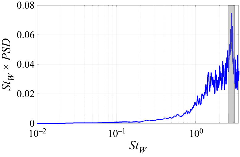
 $0.3 L$, as shown in figure 5. The boundary layers on the side surfaces follow the same behaviour with a slightly shorter separation bubble. Hairpin vortices then emanate from just downstream of the reattachment points (figure 6), with associated flow fluctuations at a relatively high frequency of
 $St_W = 2.1$, based on the pressure signal at
 $x/L = 0.45$, as shown in the power spectral density in figure 7. Similar frequencies were detected on both sides and top surfaces (not shown for brevity). These hairpin vortices were seen previously in Krajnovic & Davidson (Reference Krajnovic and Davidson2003), Kang et al. (Reference Kang, Essel, Roussinova and Balachandar2021) and Hesse & Morgans (Reference Hesse and Morgans2021). Following the time evolution of the flow topology, we observe that these vortices grow along the surfaces up to the point where their maximum length scales become of order
 $H/2$, at a streamwise location of
 $x/L \sim 0.75$. Thereafter, their interaction with the free stream leads to a break down such that their length scales become much smaller. An interaction between the smaller vortices from the top and side surfaces is then observed. Although this may be partially associated with turbulent diffusion, a periodic pattern of interaction is evident, as shown in the supplementary movie available at https://doi.org/10.1017/jfm.2023.826.
Iso-surface of zero streamwise velocity, showing the bubble in the wake region and the frontal bubbles due to boundary layer separations on the side and the top (zoomed view) body surfaces. In-plane streamlines at the mid-width body ( $z/W = 0$) are superimposed. Note that left-handed Cartesian coordinates are considered.

Iso-surfaces of  $Q$-criterion of
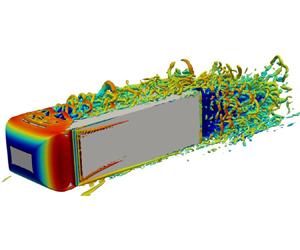
 $2 \times 10^5$ coloured by the streamwise velocity for the unforced flow, using two different three-dimensional views, showing the hairpin vortices on the body top and side surfaces.

Premultiplied power spectral density of pressure signal from a probe located at  $x/L = 0.45$,
 $y/H = 0.65$ and
 $z/W = 0$, showing the high-frequency associated with the hairpin vortices, highlighted with the grey rectangle.

On the bottom surface of the body, the confinement caused by the ground changes the flow dynamics and topology compared with the other longitudinal body surfaces. The boundary layer remains attached along the bottom surface up to the body base. However, the interaction of the smaller vortices from the side surfaces with the underbody flow forms two corner vortices on the bottom part of the body (figure 6). This disturbs the underbody flow, but does not lead to boundary layer separation. The ground boundary layer also does not exhibit any separation dynamics upstream of the wake. Previous studies have shown that the wake switching is sensitive to the underbody flow. Experimental studies have triggered wake switching by disturbing the underbody flow, for example using a passive device in the clearance between the body and the ground (Barros et al. Reference Barros, Borée, Cadot, Spohn and Noack2017; Bao et al. Reference Bao, Borée, Haffner and Sicot2022). Here, we consider that the disturbances in the underbody flow may in part be caused by the interaction of smaller vortices from other surfaces due to the boundary layer dynamics. We therefore investigate the effect of suppressing the upstream boundary layer disturbances on both the underbody flow and on wake bi-modality.
4. Suppression of upstream boundary layer separations
The effect of applying suction on the longitudinal surfaces of the Ahmed body is investigated in this section. Both the time-averaged and instantaneous properties of the flow field are considered, including the effect on the underbody flow.
4.1. Effect on wake configuration
The wake horizontal bi-modality and vertical asymmetry in the presence of suction are first explored. A summary of the results for the different cases, including the mean properties of the wake flow is shown in table 2. The spatial gradients of the pressure coefficient on the base,  $\partial C_{P}/ \partial z$ and
 $\partial C_{P}/ \partial y$, are used to characterise horizontal bi-modality and the vertical position of the wake, respectively. Figure 8 depicts the time history of
 $\partial C_{P}/ \partial z$ for the three cases. All simulations initially have no suction on any of the Ahmed body surfaces; the unforced wake was left to switch naturally for the first
 $700$ convective time units, during which it switches three times. Suction is then activated to suppress boundary layer separations, as marked by the black dashed line in figure 8, with simulations running for
 $1400$ convective time units in the presence of suction. The time evolution of
 $\partial C_{P}/ \partial z$ shows that suppressing the separation of boundary layers near the body fore end successfully suppresses wake bi-modality for both case-1 and case-3. Bi-modality suppression is evident from the single peak of the PDF of
 $\partial C_{P}/ \partial z$, as shown in figure 8. This supports a causal link between the boundary layer separations upstream of the wake and bi-modality, as recently proposed by Hesse & Morgans (Reference Hesse and Morgans2021).
Comparison of the effect of boundary layer separation suppression on the wake horizontal bi-modality, vertical asymmetry, length of the recirculation region ( $\overline {L_{rec}}$), area-averaged mean base pressure (
 $\langle \overline {C_{P-{base}}}\rangle$) and underbody bulk velocity (
 $\overline {U_b}$) (indicating the change in the momentum of the underbody flow).

Time history of horizontal pressure gradient of the pressure coefficient  $C_P$ (left) and the associated PDF for the unforced flow, case-1 (a), case-2 (b) and case-3 (c). The black dashed lines mark the starting time of the application of suction. The PDF of case-1, case-2 and case-3 are generated using the data in the presence of suction (after the black dashed line in the time history).

For case-1, where the boundary layer separations on the side surfaces are suppressed, the remaining turbulent forcing in the wake causes a stochastic switching of the wake within spatial bounds closer to the centre. The corresponding  $\partial C_{P}/ \partial z$ for these switching bounds is half of their equivalents in the unforced case. The time evolution of
 $\partial C_{P}/ \partial z$ for case-2 indicates the presence of wake bi-modality; the wake switches five times in the presence of suction. In this case, the separation of the top surface boundary layer is fully suppressed and air suction is applied through the bottom surface slit. The latter causes some disturbances in the underbody flow, leading to boundary layer separation on the ground, as will be shown in more detail in § 4.4. For case-3, boundary layer separations are suppressed on the top and sides surfaces and momentum is removed from the underbody flow. This suppresses wake bi-modality, as shown in the associated PDF in figure 8. The time evolution of
 $\partial C_P / \partial z$ shows that the wake switches between spatial bounds, which are slightly closer to the base compared with the unforced case. The wake oscillations about the symmetric position are now more rapid than in the absence of suction. The associated change in wake topology due to upstream suction is shown in Appendix B.
The vertical position of the wake, characterised by  $\partial C_{P} / \partial y$, may be influenced by changes in the underbody flow. Figure 9 shows joint PDF of the spatial gradients of the base pressure,
 $\partial C_{P} / \partial z$ and
 $\partial C_{P} / \partial y$, in the absence and presence of the upstream suction. The unforced wake (figure 9a) exhibits weak asymmetry in the vertical direction due to the effect of the underbody flow; this is consistent with the experimental results by Grandemange et al. (Reference Grandemange, Gohlke and Cadot2013a) for a similar normalised ground clearance. The weak vertical asymmetry is evident from the fact that horizontal bi-modality occurs for
 $\partial C_{P} / \partial y$ values centred within a limited spatial region around zero. This follows the competition between the horizontal and the vertical base pressure gradients proposed by Barros et al. (Reference Barros, Borée, Cadot, Spohn and Noack2017).
Two-dimensional PDF of the gradients of the base pressure coefficient in the horizontal and vertical directions  $\partial C_{P}/ \partial z$ and
 $\partial C_{P}/ \partial y$, respectively, for the unforced flow (a), case-1 (b), case-2 (c) and case-3 (d). Note that the scales of the axes are different for each case.

For case-1, in which side suction approximately symmetrises the wake horizontally, the vertical position is seen to be similar to that for the unforced case, as shown in figure 9(b). It will be seen later that negligible change is observed in the mean underbody flow and the top shear layer for this case, suggesting that bi-modality suppression is mainly related to the suppression of the upstream boundary layer dynamics. For both case-2 and case-3, the underbody flow is directly disturbed by the application of underbody suction. The vertical position of the wake is seen to be altered, moving away from the ground, as shown in figures 9(c) and 9(d) and also indicated by figure 22 in Appendix B. This weak vertical asymmetry in the opposite sense to the unforced flow is consistent with the experimental results of Barros et al. (Reference Barros, Borée, Cadot, Spohn and Noack2017), who also saw that disturbing the underbody flow inverts the vertical (wall-normal) position of the wake with a positive pressure gradient. It will be seen later in § 4.4 that the change in the vertical balance of the wake is linked to the dominance of the upwash flow for these two cases, which is relevant to the change in the momentum of the underbody flow concomitant with the suppression of the separation of the top surface boundary layer.
To conclude, these results confirm that bi-modality is affected by the upstream boundary layer separations. By suppressing these separations, the interaction of the vortices upstream of the wake is interrupted, affecting the wake bi-modality. Suppressing the boundary layer separations on the side surfaces completely suppresses bi-modality and symmetrises the wake. On the other hand, applying suction on the top and bottom surfaces has an almost negligible effect on bi-modality. When suction is applied on all four surfaces, the symmetrised wake oscillates rapidly with quite large spatial bounds. In the last two scenarios, the underbody flow is affected by suction. Wake bi-modality is known to exhibit sensitivity to this, and it will form the topic of further discussions in § 4.4.
4.2. Effect on boundary layer separation
The effect of applying the upstream suction on the boundary layers of the longitudinal body surfaces is now investigated. As described in § 2, spatially independent steady suction with a velocity equal to the magnitude of the free-stream velocity is applied normal to the surfaces. Suction slits are placed inside the separation bubble formed just aft the body nose at a streamwise position of  $x/L \sim 0.15$. The same streamwise slit position is used on all body surfaces. The effect of this suction on the Ahmed body boundary layers upstream of their large-scale separation at the base is now investigated.
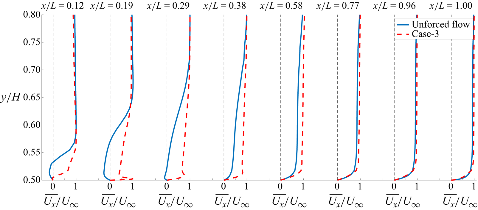
Figures 10 and 11 compare the streamwise time-averaged velocity along the top and side surfaces of the body, respectively, for the unforced flow, case-1 and case-3. In the absence of suction, the boundary layers separate at  $x/L \sim 0.08$ on the top and side surfaces, reattaching at
 $x/L \sim 0.30$ on the top surface and at
 $x/L \sim 0.26$ on the sides. The lengths of the separation bubbles on either side of the body are identical and slightly shorter than on the top. The boundary layers on the bottom surface of the body and the ground remain attached throughout. The shape factor, defined as the ratio of boundary layer displacement and momentum thicknesses, at the separation location is
 $\sim$1.3, indicating that all boundary layers are fully turbulent prior to their separation at the base.
Streamwise mean velocity at different streamwise locations on the top surface of the Ahmed body at  $z/W = 0$ for the unforced flow and case-3 shown by blue and red lines, respectively.

Streamwise mean velocity at different streamwise locations on the side surfaces of the Ahmed body at  $y/H = 0$ for the unforced flow and side 1 and side 2 for case-1, shown by blue, red lines and the black triangles, respectively.

When suction is applied on the top surface, as in case-2 and case-3, a tiny extent of boundary layer separation and reattachment is seen upstream of the slit. There is a hint of a tiny boundary layer separation at  $x/L \sim 0.12$ in figure 10. The boundary layer then grows attached to the wall downstream of the slit, as shown by the streamwise velocity for
 $x/L > 0.15$. The effect of the suction slit is that the boundary layer effectively grows from zero thickness downstream of the slit with no evidence of significant separation upstream of the base (Schlichting & Gersten Reference Schlichting and Gersten2003). Figure 11 shows that suction has similar impact on the boundary layers on both sides, also causing them to remain attached along the length of the body.
For the unforced flow, the boundary layer thicknesses at the Ahmed body base (just ahead of where the large-scale flow separation occurs) are identical on the top and side surfaces. The velocity profile of the top and side boundary layer exhibits differences closer to the wall, this could be attributed to different levels of turbulent intensity. Suction is seen to have very little effect on the time-averaged properties of the boundary layers near the base i.e. at  $x/L \sim 1.0$. Top upstream suction slightly reduces the thickness of the top boundary layer, with
 ${\delta }_{{0.99}}/H \sim 0.48$ compared with
 ${\delta }_{{0.99}}/H \sim 0.50$ without suction. Side upstream suction causes negligible change in the thickness of the side surface boundary layers. All boundary layers remain turbulent at the base in the presence of upstream suction.
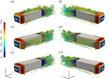
Suppressing the upstream boundary layer separations acts to reduce the turbulent fluctuations arising from the formation and development of the hairpin vortices, as discussed in § 3. This can be seen in figure 12, which shows the Q-criterion for different suction arrangements. Both the hairpin and the smaller vortices evidenced in the unforced flow (figure 6) are suppressed on the surfaces where suction is applied. In case-1, where suction is applied on the side surfaces, these vortices are suppressed on the sides. This isolates the vortical structures on the top surface and the underbody flow, suppressing the interactions that take place with side surface vortical structures in the absence of side suction. The resulting effect on the TKE just upstream of the base (at  $x/L = 0.88$) is shown in figure 13. For case-1, the TKE on the sides is diminished, as shown in figure 13(b). This is consistent with the experimental results, where higher turbulent intensity on the side boundary layers was found to be linked to increasing wake switching events (Burton et al. Reference Burton, Wang, Smith, Scott, Crouch and Thompson2021).
Iso-surfaces of  $Q$-criterion of
 $2 \times 10^5$ coloured by the streamwise velocity, using two different three-dimensional views, for case-1 (a,b), case-2 (c,d) and case-3 (e, f), showing the effect of suction on the fluctuations along the body top and side surfaces.

Turbulent kinetic energy (TKE) on a vertical plane at a streamwise position of  $x/L =0.88$, for the unforced flow case (a), case-1 (b), case-2 (c) and case-3 (d). Note that left-handed Cartesian coordinates are considered.

Similarly, for case-2 (figure 13c), the application of suction on the top surface initially suppresses vortices on the top surface. The vortices on the side surfaces interact with the top boundary layer and underbody flow downstream, increasing the disturbances towards the base, as shown by the relatively higher values of TKE. The effect of the underbody suction on the underbody flow is considered in § 4.4. For case-3 (figure 13d), the vortical structures on the top and side surfaces are reduced. In this case, any remaining switching of the wake is attributed to the turbulent fluctuations in the wake region and the underbody flow rather than the turbulent fluctuations caused by boundary layer separations. The TKE is reduced on the top and side surfaces compared with the unforced case.
4.3. Effect on mean wake flow
In this section, the results of applying suction on the time-averaged wake flow are investigated. The length of the recirculation bubble is demarcated by the maximum streamwise distance between the base and the profile of zero streamwise mean velocity. Its change as compared with the unforced case,  $\Delta \overline {L_{rec}}$, is reported in table 2 for the different upstream suction cases. A
 $3\,\%$ increase in the bubble length occurs for case-1, for which the underbody flow remains undisturbed. Case-2 exhibits no change, even though the suction on the bottom body surface disturbs the underbody flow. Case-3, also with a disturbed underbody flow, exhibits no change in this length. The bubble length is related to shear layer curvature, with a longer bubble being associated with smaller curvature, affecting shear layer stability. A longer bubble is also associated with base pressure recovery and consequently drag reduction (Hsu et al. Reference Hsu, Pastur, Cadot and Parezanović2021).
We now discuss the change in the mean base pressure in more detail. This depends not only on the length of the recirculation region, but also on the wake configuration i.e. horizontal bi-modality and vertical asymmetry. For both case-1 and case-3, horizontal bi-modality is suppressed (even if the oscillation bounds of the remaining wake fluctuations differ). Symmetrising the wake horizontally is known to have a favourable effect on base pressure recovery (Haffner et al. Reference Haffner, Borée, Spohn and Castelain2020; Ahmed & Morgans Reference Ahmed and Morgans2022). The link between the mean base pressure recovery and the vertical asymmetry of the wake was previously investigated experimentally by Haffner et al. (Reference Haffner, Borée, Spohn and Castelain2020). As the wake loses its vertical symmetry, the base pressure decreases; any horizontal bi-modality disappears when the wake leaves the weak vertical asymmetry region. Barros et al. (Reference Barros, Borée, Cadot, Spohn and Noack2017) proposed that this is due to the competition between the horizontal and vertical base pressure gradients. Horizontal bi-modality occurs only for weak vertical asymmetry. The mean base pressure follows an asymmetric parabolic profile as a function of the vertical position of the wake, with the vertex occurring for a vertically symmetric wake (Haffner et al. Reference Haffner, Borée, Spohn and Castelain2020). The wake vertical balance depends mainly on the momentum of the underbody flow and underbody disturbances; increased disturbances and reduced momentum cause the wake to move away from the weak vertical asymmetry region, leading to a static vertical asymmetric wake (Barros et al. Reference Barros, Borée, Cadot, Spohn and Noack2017).
The effect of the upstream boundary layer suction on the base pressure recovery is investigated using the area-averaged mean base pressure, denoted  $\langle \overline {C_{{{P\text {-}base}}}}\rangle$. The change in this value as compared with the unforced flow,
 $\varDelta \langle \overline {C_{{{P\text {-}base}}}}\rangle$, is shown for the different suction cases in table 2. The highest base pressure recovery,
 $14\,\%$, is reported for case-1. For this case, horizontal bi-modality is suppressed, the vertical balance of the wake is unchanged and the separation bubble is slightly elongated compared with the unforced case. The base pressure recovery here is therefore attributed primarily to horizontal bi-modality suppression and horizontal wake symmetrisation. For case-2, the base pressure recovery is
 $2\,\%$. This is attributed to the reflected weak vertical asymmetry but with horizontal wake bi-modality persisting. For case-3, the base pressure recovery is
 $7\,\%$. This is attributed to the wake being horizontally symmetrised with reflected weak vertical asymmetry; the large wake oscillations are likely to be limiting the base pressure recovery as compared with case-1. These results are consistent with the experimental results by Haffner et al. (Reference Haffner, Borée, Spohn and Castelain2020), where the reflected weak vertical asymmetry promotes the gain in base pressure recovery.
Finally, we investigate the effect of suppressing the upstream boundary layer dynamics on the downstream shear layer mean thickness and growth rate in the wake. These can be characterised using the vorticity thickness,  $\delta _{\omega,n}$, defined as the ratio of the maximum velocity difference to the maximum mean shear stress, i.e.
 $\delta _{\omega,n} = {\Delta U}_{max}/ |{\partial U / \partial n}_{max}|$, where
 $n \in [y,z]$ (Djilali & Gartshore Reference Djilali and Gartshore1991). The numerator represents the difference between the maximum local velocity at the centre of the shear layer bounding the separation bubble and the minimum velocity on the low-speed side of the shear layer i.e. in the separation bubble. The centre of the shear layer here is determined based on the maximum fluctuating velocity profile (Djilali & Gartshore Reference Djilali and Gartshore1991). The visual thickness of the shear layer is double the vorticity thickness
 $\delta _{{\omega,n}}$. The slope of the vorticity thickness
 ${\rm d}{\delta }_{{\omega,n}} / {{\rm d}\kern0.06em x}$ is used to measure the spread or growth rate of the shear layer in the streamwise direction.
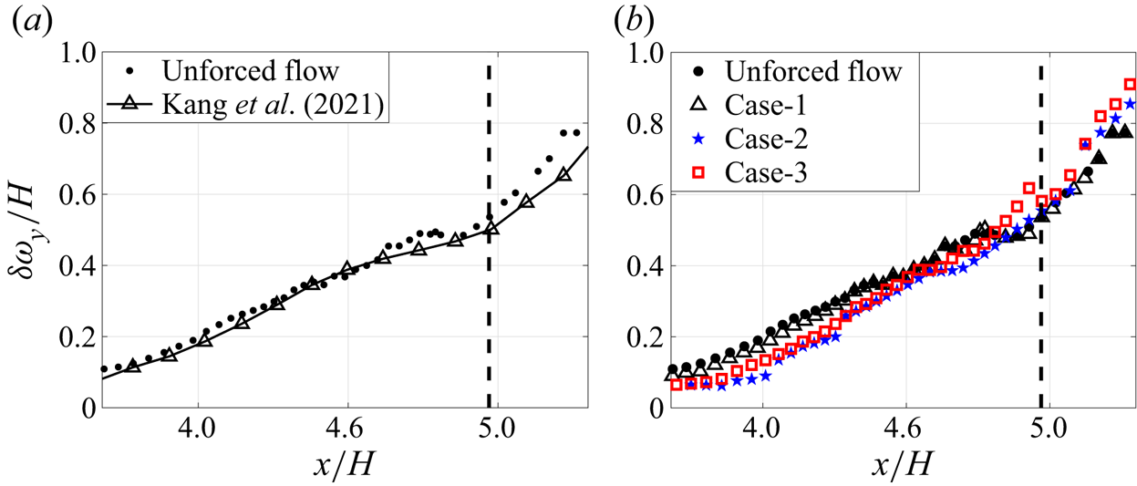
As shown in figure 14(a), for the unforced flow, the separated wake shear layers initially grow linearly (with different growth rates) in the wake, matching the growth reported by Kang et al. (Reference Kang, Essel, Roussinova and Balachandar2021) for the wake of an Ahmed body. The linear growth is similar to that of a free shear layer, with Bres & Colonius (Reference Bres and Colonius2008) showing that the presence of a recirculation bubble changes the flow entrainment and accordingly the shear layer thickness and growth rate. From the gradient of the data in figure 14(a), it can be seen that the growth rate of the top shear layer varies in the streamwise direction, with a value of  $0.38$ in the near-wake region (
 $x/H < 4.7$) and
 $0.20$ for
 $4.7 \leqslant x/H \leqslant 5.05$. The near-wake values are similar to those of the shear layer separated from a wall-mounted block (Agelinchaab & Tachie Reference Agelinchaab and Tachie2008). Downstream of the recirculation region (marked by the black dashed line in figure 14a), the top shear layer exhibits rapid linear growth with a relatively higher rate of
 $0.92$, due to the suppression of the maximum shear stresses.
Wake shear layer vorticity thickness for the top shear layer of the unforced flow, compared with data from Kang et al. (Reference Kang, Essel, Roussinova and Balachandar2021) (a). The effect of suppressing the upstream boundary layer separation on the top surface shear layer in the wake (b). The black dashed line marks the length of the recirculation region.

Figure 14(b) compares the vorticity thickness of the top shear layer in the presence and the absence of the upstream suction. In the absence of top surface suction, as in case-1, the top shear layer thickness exhibits negligible change compared with the unforced flow. When top surface suction is applied (case-2 and case-3), the top surface shear layer is thinner in the near-wake region ( $x/H < 4.6$), but its growth rate increases slightly compared with the unforced case. The top surface shear layers have similar thicknesses for
 $4.5 < x/H < 4.8$, with the growth rate for case-3 then rapidly increasing towards the end of the recirculation bubble, leading to a slightly thicker shear layer than that for the unforced flow and the other two cases.
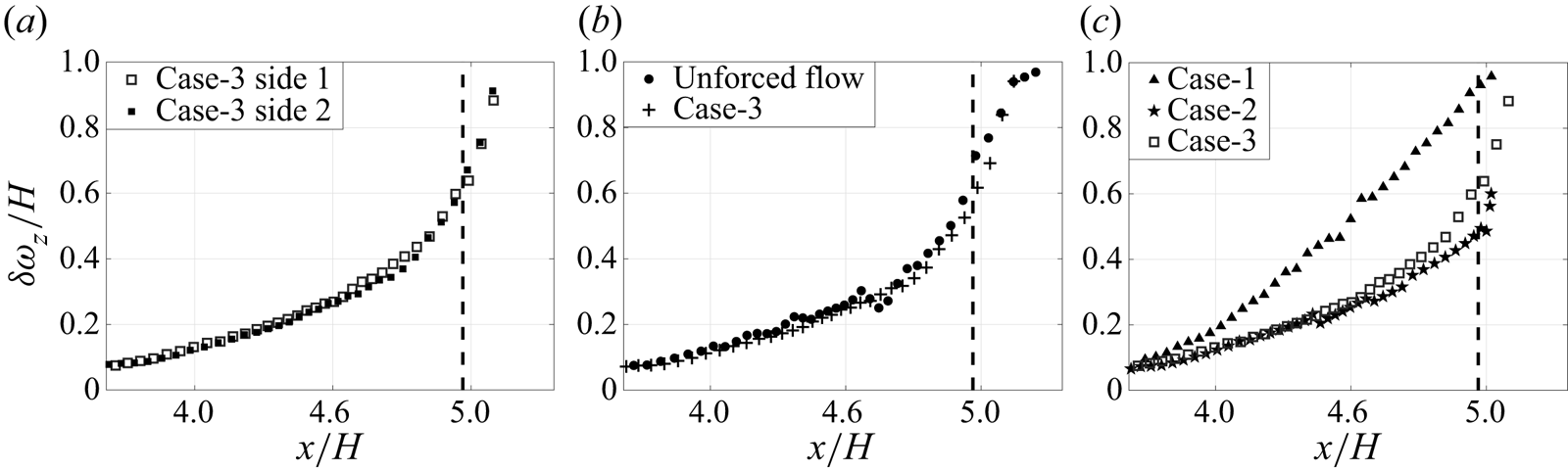
Figure 15(a) compares the shear layer thickness on the two sides for case-3. The upstream side suction has an identical effect on both side shear layers in the wake. Similarly, identical suction effect on the side surfaces is seen in case-1 (not shown for brevity). Figure 15(b) compares the shear layer on side 1 for case-3 with its counterpart in the unforced flow, showing negligible difference. This is consistent with the wake oscillations being large for both cases, with similar associated shear layer curvatures.
Wake shear layer vorticity thickness for the shear layers on side 1 and side 2 for case-3 (a). Comparison of the shear layer thickness on side 1 for the unforced flow and case-3 (b). Comparison of the shear layer thickness on side 1 for case-1, case-2 and case-3 (c). The black dashed line marks the length of the unforced flow recirculation region.

As suction has a similar effect on both sides, we proceed with comparing side 1 only for brevity. Figure 15(c) shows the shear layer thicknesses on side 1 for all three cases. Case-1 exhibits a much thicker shear layer than case-3 (which is similar to the unforced case), with the thickness almost double for  $4.2 < x/L < 5.1$. The shear layer also exhibits linear growth with larger growth rates than for case-3. For case-2, there is no upstream suction on the sides. In the near-wake region, up to
 $x/L = 4.5$, the side wake shear layers exhibit negligible change in thickness profile compared with case-3 or the unforced flow. Further downstream, a slight reduction in the shear layer thickness of case-2 can be seen compared with case-3.
We conclude that a given wake shear layer thickness is affected by the dynamics of the corresponding upstream boundary layer, and also by the interaction with the adjacent shear layers. Generally, suppressing the dynamics of the upstream boundary layer only leads to a thicker wake shear layer when the adjacent perpendicular shear layers remain unaffected, as occurs for case-1. The underbody flow is important; disturbing this has an indirect effect on wake shear layer thickness. Where underbody flow changes are insufficient to push the wake away from the weak vertical asymmetry region (as will be shown in § 4.4), the side shear layer thickness exhibits a slight change in both the presence and the absence of boundary layer separations on the sides, as seen in both case-2 and case-3. This confirms the complex interaction of all the parameters considered in this analysis.
4.4. Effect on the underbody flow
It is known that the momentum flux and disturbances of the underbody flow are important parameters in determining the wake configuration. Grandemange et al. (Reference Grandemange, Gohlke and Cadot2013a) and Barros et al. (Reference Barros, Borée, Cadot, Spohn and Noack2017) showed that the underbody momentum influences the vertical balance of the wake. A moderate reduction in the underbody momentum inverts the vertical position of the wake, but its vertical asymmetry remains weak. For a relatively larger reduction in the underbody momentum, the wake asymmetry becomes more pronounced such that it can no longer be considered weak, and the wake becomes static, without horizontal switching (Barros et al. Reference Barros, Borée, Cadot, Spohn and Noack2017). However, the required change in underbody momentum for the wake to reverse its weak vertical asymmetry or to exhibit strong vertical asymmetry (with bi-modality inhibited) remains unclear. We now consider the effect of the different upstream suction patterns on the underbody flow in the present study.
The effect of suppressing boundary layer separations on the mean underbody flow can be investigated by considering the bulk velocity ( $U_{b}$) of the underbody flow, which controls the momentum flux in this region. The underbody bulk velocity is calculated by integrating the mean velocity over the cross-sectional area of the underbody region i.e.
 $C \times W$. In the absence of suction on the bottom surface, the ratio of the mean bulk velocity to the free-stream velocity (
 $\overline {U_{b}} / U_{\infty }$) is approximately
 $\sim$0.88 close to the back end of the body, similar to the value obtained by Castelain et al. (Reference Castelain, Michard, Szmigiel, Chacaton and Juvé2018) for a truck geometry. The changes in the mean bulk velocity with reference to the unforced flow are summarised in table 2. Changes are evident for both case-2 and case-3, for which suction occurs on the bottom surface of the body.
For case-2, in which suction is applied on both the top and bottom surfaces of the body, the bulk velocity of the underbody flow (and accordingly the momentum flux) is reduced by  $1\,\%$. The bottom surface boundary layer remains attached while the ground boundary layer separates at
 $x/L \sim 0.12$ and reattaches at
 $x/L \sim 0.37$. Similarly, for case-3, with suction on all four surfaces, the ground boundary layer separates at around
 $x/L \sim 0.12$ and reattaches at
 $x/L \sim 0.4$, the bottom surface boundary layer remains attached and the deficit in the underbody bulk velocity is
 $3\,\%$. The difference between the bulk velocity deficits for case-2 and case-3 suggests that the side boundary layer separations (present for case-2 but suppressed for case-3) augment underbody disturbances and limit the momentum reduction. For both of these cases, the wake exhibits a reflected vertical asymmetry, which remains weak, consistent with the link to underbody momentum reduction identified in the literature. We note that, for case-3, horizontal bi-modality is suppressed with quite large oscillation bounds, while for case-2 the wake bi-modality persists.
Given that the reduction in the underbody momentum for both case-2 and case-3 is very minor, the reflection of the vertical wake position might be attributable to the suppression of top boundary layer separation. To probe this further, we introduce a new case, case-4, with only top surface suction; the underbody flow remains undisturbed and the top boundary layer separation is suppressed. The effect on wake configuration is captured via  $\partial C_{P}/ \partial z$ and
 $\partial C_{P}/ \partial y$ in figure 16. Horizontal wake bi-modal switching remains and the joint PDF of
 $\partial C_{P}/ \partial z$ and
 $\partial C_{P}/ \partial y$ in figure 16(b) indicates reflected weak vertical asymmetry of the wake, similar to case-2. This suggests that the change in the vertical wake balance in case-2 and case-3 is primarily due to the suppression of the top boundary layer separation rather than changes in the underbody flow. Overall, these results confirm that, since our studies remain in the regime of weak vertical symmetry throughout, changes in the side surface boundary layer dynamics are the dominant cause of changes in horizontal wake bi-modality.
Time history of horizontal gradient of the pressure coefficient  $\partial {C_{P}} / \partial z$ and the associated PDF for the unforced flow and case-4 where suction is applied on the top surface only (a). The black dashed line marks the starting time of the application of suction. Two-dimensional PDF of the gradients of the base pressure coefficient in the horizontal and vertical directions
 $\partial C_{P}/ \partial z$ and
 $\partial C_{P}/ \partial y$, respectively, after switching on suction on the top surface (case-4) (b).

The rest of this section is focused on investigating the underbody disturbances across the different cases, building on our earlier observation in § 3 that vortices interacting between the different surfaces affect the underbody flow. The disturbances induced in the underbody region can be seen by comparing the TKE ( $0.5 \times (\overline {{u'}^2}+\overline {{v'}^2}+\overline {{w'}^2})$, where
 ${u', v',w'}$ are the fluctuating velocity components in the
 $x,y,z$ directions, respectively) for the different cases. Figure 17 compares the area-averaged TKE,
 $\langle TKE\rangle$, at different sections (
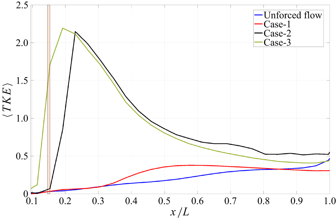
 $C \times W$) along the underbody region for the unforced flow and the different forcing cases. For the unforced flow, the TKE increases gradually along the underbody, following the development of the boundary layers on the bottom surface and the ground. For case-1, the TKE exhibits a slight increase around
 $x/L \sim 0.35$ compared with the unforced flow and decreases for
 $x/L > 0.8$. This difference is likely to be linked to the suppression of the side vortices. At the base, the area-averaged TKE for case-1 is
 $34\,\%$ less than for the unforced flow. Its contours are horizontally symmetric, as shown in figure 18(b), this being attributable to the suppression of the side boundary layer disturbances.
Area-averaged TKE at different sections ( $C \times W$) of the underbody in the streamwise direction for the unforced flow case (blue), case-1 (red), case-2 (black) and case-3 (green).

Contours of TKE of the underbody flow at the base ( $x/L=1$) for the unforced flow (a), case-1 (b), case-2 (c) and case-3 (d).

For both case-2 and case-3, where the underbody flow is affected by bottom surface suction, the TKE increases by an order of magnitude downstream of the slits. It peaks at  $x/L = 0.23$ for case-2 and at
 $x/L = 0.2$ for case-3, then decays towards the base for both cases due to dissipation. This could be attributable to the separation of the ground boundary layer that occurs in both cases.
Differences between case-2 and case-3 must be linked to the effect of suppressing the side surfaces boundary layer separations. Compared with the unforced flow, the area-averaged TKE at the base is  $18\,\%$ higher for case-2, but
 $4\,\%$ lower for case-3. Thus, the base
 $\langle TKE\rangle$ is reduced compared with the unforced flow for both case-1 and case-3, and appears to be linked to the suppression of the side boundary layer separations. The reduction in base
 $\langle TKE\rangle$ for case-1 is an order of magnitude larger than for case-3, suggesting that, for case-3 (which has suction on all four surfaces), the reduction in base
 $\langle TKE\rangle$ due to suppressing the side disturbances is to some degree compensated by the disturbances induced by the bottom suction. Figure 18 shows an approximately horizontally symmetric base profile for case-3, with higher TKE in the boundary layers and at mid-height of the gap, showing where the vortical structures are residing.
To conclude, these results show that, in the absence of bottom suction, the underbody flow is disturbed indirectly by the boundary layer separations on the sides, confirming the proposed interaction of the vortices from top and side surfaces, discussed in § 3. Suppressing the side separations, as in case-1, is seen to reduce the TKE of the underbody region at the base. Applying suction through the bottom surface imposes direct disturbances in the underbody flow, indicated by the relatively higher TKE of the flow beneath the base, as seen in case-2. Suppressing boundary layer separations on the sides reduces the disturbances introduced due to bottom suction, leading to a slight reduction of the underbody TKE at the base, as in case-3. The change in the TKE of the underbody flow is expected to affect the entrainment of the shear layer separated from the bottom surface of the body, which accordingly affects the wake dynamics.
5. Conclusion
In this study we have investigated the link between the upstream dynamics – related to boundary layer separations – and bi-modality in the turbulent wake of the square-back Ahmed body in close proximity to ground. We propose that wake bi-modal switching is triggered by the interaction of the vortices formed on the top and side surfaces of the body, which also affects the underbody flow.
Steady and spatially independent suction was used to suppress boundary layer separations on the longitudinal body surfaces. Different cases with suction on different combinations of body surfaces were investigated. When boundary layer separation is suppressed on only the wall-normal surfaces (side surfaces), the wake becomes horizontally symmetric while retaining its vertical position. Supressing the side boundary layer disturbances in this case was found to have a direct effect on the disturbances of the free shear layers separated off the side surfaces in the wake region. It also has an indirect favourable effect on the turbulent fluctuations in the underbody flow. These results support the proposed mechanism of the link between wake bi-modality and vortex interaction. This represents a new promising strategy for controlling wake bi-modality indirectly i.e. without directly forcing the wake.
When boundary layer separation is suppressed on only the wall-parallel surfaces (top and bottom), the wake bi-modality remains, accompanied by an inversion of vertical wake asymmetry. This change in the wake vertical balance is related to the suppression of top boundary layer separation with a small effect of the momentum reduction in the underbody flow due to bottom suction, preserving the weak vertical asymmetry of the wake.
When suction is applied on all four longitudinal surfaces of the body, suppressing the separation of the boundary layer on the top and side surfaces, and disturbing the underbody flow, horizontal bi-modality is suppressed, with the wake exhibiting larger oscillation bounds compared with the side-only suction. The study has shown that the disturbances induced in the underbody flow become partly cancelled close to the base by the compensating effect of suppression of the side boundary layer disturbances. The wake is weakly asymmetric in the vertical direction, with the asymmetry inverted compared with the unforced flow. This suggests that bi-modality suppression is due to suppression of the side boundary layer disturbances, similar to side-only suction.
These results represent a first step towards investigating upstream control strategies (which might be more cost effective than steady suction) for bi-modality suppression. Such an approach offers promise for achieving drag reduction as well as bi-modality suppression, something that actuating the wake directly has been unable to fully achieve, especially when wake actuation affects the free shear layers.
Supplementary movie
Supplementary movie is available at https://doi.org/10.1017/jfm.2023.826.
Acknowledgements
The authors acknowledge the computational resources provided by Imperial College High Performance Computing (HPC) and ARCHER2 (The UK National Supercomputing Facility), used in this study. The authors also acknowledge the PhD scholarship from the Islamic Development Bank for funding this study.
Funding
This work was supported by the PhD scholarship from the Islamic Development Bank.
Declaration of interests
The authors report no conflict of interest.
Appendix A
This appendix shows the details of the mesh used in this study, which is similar to the mesh used in Ahmed & Morgans (Reference Ahmed and Morgans2022). An unstructured hexahedral-dominant grid was used to optimise the usage of computational resources. This mesh was generated in StarCCM+ software using the trimmer cells model, which trims the core hexahedral cells with polyhedral cells at the boundaries. Figure 19 shows vertical and horizontal planes of the mesh passing through the centre of the body (point  $(0,0,0)$). Orthogonal cells were generated near the solid boundaries using the prism layer model, shown in the zoomed view of figure 19. This is important to improve the mesh quality near the wall and to resolve the boundary layer flows.
Vertical (a,b) and horizontal (c,d) planes at  $z/W=0$ and
 $y/H = 0$, respectively, show the mesh. The red circle shows the position of the zoomed view on each plane, depicting the near-wall prism layers on the body fore end.

The mesh sensitivity study was performed to ensure the independence of the solution on the mesh refinement. Three different grid sizes ( $9$,
 $11$ and
 $15$ million cells) were considered. The refinement criteria were based on increasing the cell count in all mesh regions, i.e. the prism layers’ region, the near wake and around body refined regions and the far field coarse region. The prism layers, in the near-wall region, were refined to fully resolve the boundary layer for each of the three grids. This is indicated by the value of
 $\overline {y^+} \leqslant 1$, as shown in figure 20 for the case of
 $11 \times 10^6$ cells. The size of the cells is increased by a growth rate of
 $1.1$ between the different mesh zones (Hesse & Morgans Reference Hesse and Morgans2021), shown in figure 19.
Distribution of the time-averaged  $y^+$ on the Ahmed body for the unforced case (left) and for case-3 where suction is applied on all body surfaces.

The metrics used to examine the mesh size were the drag coefficient,  $\overline {C_{D}}$, the average base pressure,
 $\overline {C_{{P\text {-}base}}}$, and the normalised length of the recirculation region,
 ${\overline {L_{rec}}}/{H}$, as shown in table 3. These metrics were compared with their equivalents in the experiments of Grandemange et al. (Reference Grandemange, Gohlke and Cadot2013a) and the numerical study of Hesse & Morgans (Reference Hesse and Morgans2021), as both were conducted at
 $Re_H \sim 3.3 \times 10^4$. The values of all metrics are reasonably comparable to the numerical study by Hesse & Morgans (Reference Hesse and Morgans2021). Compared with Grandemange et al. (Reference Grandemange, Gohlke and Cadot2013a) experiments, the maximum difference in the length of the recirculation region is
 $2\,\%$, with the mid-size grid (
 $11$ million cells) capturing a similar value. The maximum deviation from the experimental value in the average base pressure was approximately
 $15\,\%$. Comparing with Fan et al. (Reference Fan, Xia, Chu, Yang and Cadot2020), the deviation becomes
 $4\,\%$, implying that the experimental base pressure values span a range. Following these comparisons, the mid-size grid i.e. the
 $11$ million cells, is deemed sufficient for the simulation. The value of
 $\overline {y^+}$ for the unforced case is
 $0.58$, indicating that the near-wall flow is fully resolved. In the presence of suction
 $\overline {y^+}$ increases to
 $0.88$ just downstream of the slits, as shown in figure 20, which is still sufficient to resolve the boundary layers. The average cell size in the wake region satisfies the LES requirement of resolving the Taylor microscale (Howard & Pourquie Reference Howard and Pourquie2002).
Comparison of the time-averaged flow metrics for different mesh sizes, including the time-averaged drag ( $\overline {C_D}$), time-averaged base pressure (
 $\overline {C_{Pbase}}$), time-averaged recirculation length (
 $\overline {L_{rec}}$) and time-averaged
 $y^+$. These grids are similar to the grids used in Ahmed & Morgans (Reference Ahmed and Morgans2022).

Appendix B
This appendix shows the effect of upstream suction on the mean wake topology. Figures 21 and 22 depict the top and side views of the separation bubbles, respectively, superimposed with mid-plane streamlines. The associated toroidal vortex, occupying the near-wake region, is also shown for each case. Figures 21(a) and 21(b) show that the conditional averages of the asymmetric wake correspond to  $\partial C_P / \partial z < 0$ and
 $\partial C_P / \partial z > 0$, respectively, in the absence of suction. It can be seen that, for each asymmetric state, the centre of the wake is tilted towards one side and the toroidal vortex is skewed towards the base on the opposite side. In the presence of suction, the time-averaged wake is horizontally symmetric for case-1, case-2 and case-3, as shown in figure 21. The streamwise location of the toroidal vortex influences base pressure recovery (Ahmed & Morgans Reference Ahmed and Morgans2022). Comparing the toroidal vortices in the three cases, it can be seen that case-1 has the farthest toroidal vortex-to-base distance with the highest base pressure recovery (
 $14\,\%$) of the three cases, as discussed in § 4.3. The toroidal vortex of case-2 is the closest to the base associated with the minimum base pressure recovery of
 $2\,\%$. For case-3, the toroidal vortex resides at mid-streamwise position compared with case-1 and case-2, with a moderate base pressure recovery of
 $7\,\%$.
Top view of the separation bubble demarcated by the iso-surface of zero streamwise mean velocity for the asymmetric wake when  $\partial C_P / \partial z < 0$ (a), asymmetric wake when
 $\partial C_P / \partial z > 0$ (b), case-1 (c), case-2 (d) and case-3 (e). In-plane streamlines at
 $y/H = 0$ are superimposed for each case. Air flows from left to right. The blue slot on the surface indicates the suction slit. The associated toroidal vortices defined as
 $C_P$ iso-surface of
 $-0.22$ and coloured by the mean streamwise velocity are shown on the right side of the graph. Note that left-handed Cartesian coordinates are considered.

Side view of the separation bubble demarcated by the iso-surface of zero streamwise mean velocity for the asymmetric wake when  $\partial C_P / \partial z < 0$ (a), asymmetric wake when
 $\partial C_P / \partial z > 0$ (b), case-1 (c), case-2 (d) and case-3 (e). In-plane streamlines at
 $y/H = 0$ are superimposed for each case. Air flows from left to right. The blue slot on the surface indicates the suction slit. The associated toroidal vortices defined as
 $C_P$ iso-surface of
 $-0.22$ and coloured by the mean streamwise velocity are shown on the right side of the graph. Note that left-handed Cartesian coordinates are considered.

The side view, shown in figure 22, depicts the time-averaged vertical location of the wake. It can be seen that the wake in the absence of suction resides towards the ground for both asymmetric position, as shown in figures 22(a) and 22(b), where the wake is dominated by downwash flow. Similarly, the wake of case-1 is tiled slightly towards the ground, as shown in figure 22(c). In both case-2 and case-3, the wake moves away from the ground following the reflected vertical asymmetry caused by the upwash flow, as shown in figures 22(d) and 22(e). The toroidal vortices of case-2 and case-3 are slightly tilted away from the base on the top side, following the reflected weak vertical asymmetry.