Carbon nanotube (CNT) arrays (herein referred to as turfs) are large groups of CNTs aligned nominally vertically along their growth direction. They exhibit exceptional compressibility and elastic recovery.[Reference Cao, Dickrell, Gregory Sawyer, Ghasemi-Nejhad and Ajayan1] These turfs[Reference McCarter, Richards, Mesarovic, Richards, Bahr, McClain and Jiao2] (sometimes also called forests[Reference Qi, Teo, Lau, Boyce, Milne, Robertson and Gleason3]) of CNTs also demonstrate buckling behavior in compression,[Reference Hutchens, Hall and Greer4, Reference Zbib, Dj Mesarovic, Lilleodden, McClain, Jiao and Bahr5] and when strongly bonded to another surface can stretch to several times their nominal length due to the extension of pre-bent segments within the turf.[Reference Johnson, Bahr, Richards, Richards, McClain, Green and Jiao6] This interesting mechanical performance, when coupled with the promise of high thermal or electrical conductivity,[Reference Xu and Fisher7] has led to research directed at their possible use in thermal interface materials or electrical contacts in flexible systems. Unfortunately, CNT turfs may not always make good contact to metal surfaces for thermal or electrical transport applications.
For some catalysis and sensing applications, or high-temperature service in oxidizing environments, the elastic response and transport behavior remain very attractive, but carbon may not be the material of choice to be exposed to all environments. Metals such as nickel (Ni), gold (Au), platinum (Pt), and copper (Cu) may present some clear advantages in some low-density, high surface area applications. Dealloying, the selective dissolution of the less noble element of an alloy resulting in a pore–ligament composite structure, is the method of choice for the production of nanoporous metals.[Reference Erlebacher, Aziz, Karma, Dimitrov and Sieradzki8]
However, nanoporous metals formed by dealloying suffer from macroscopically brittle behavior due to plastic deformation in individual ligaments.[Reference Biener, Hodge and Hamza9] With little or no barriers for slip in the pure dealloyed materials, work-hardening is not possible within ligaments and extremely localized plasticity, once initiated, leads to a few ligaments necking and what appears to be macroscopically brittle failure of the structure under load.[Reference Biener, Hodge and Hamza9]
Combining the elastic performance and flexibility of CNT turf structures with the properties of metals can offer new possibilities. CNT turfs can exhibit a much lower overall density (≈2 vol%[Reference Johnson, Bahr, Richards, Richards, McClain, Green and Jiao6]) than nanoporous metals (≈30 vol% [Reference Sun, Kucera, Burger and Balk10]). One possible direction to achieve this synergy is to utilize a CNT turf as a template for subsequent metallic coatings. Electrodeposited coatings have been successfully applied to nanoporous metals and shown to increase the barriers to dislocation transmission within ligaments, greatly improving the overall strength of the material.[Reference Abdolrahim, Bahr, Revard, Reilly, Ye, Balk and Zbib11] Similarly, there are examples in the literature of metallization of carbon fibers using electroless deposition[Reference Zhang, Zhou and Ren12] and electroplating.[Reference Hua, Liu, Yao, Wang, Ma and Liang13] CNT arrays have been coated conformally using chemical vapor deposition (CVD) with iron[Reference Hildreth, Cola, Graham and Wong14] (the resulting coating was identified as an iron oxide, but the authors posit that the Fe oxidized upon exposure to air between growth and characterization). Atomic layer deposition (ALD) has also been carried out on CNT arrays,[Reference Jin, Jun, Hong and Jeon15] but ALD processes still have a limited range of materials that can be utilized to create conformal metallization. Conformal CdTe coatings[Reference Camacho, Morgan, Flores, McLeod, Kumsomboone, Mordecai, Bhattacharjea, Tong, Wagner, Flicker, Turano and Ready16] have been grown with CVD on CNT arrays in photovoltaic applications.
Computational studies of multilayer metallic core–shell nanowires have predicted that for Cu–Ni systems it is possible to form materials with dimensions of the order of 10s of nm in diameter that exhibit pseudoelastic behavior that can accommodate strains of the order of 20% with no permanent deformation due to twinning and detwinning.[Reference Abdolrahim, Mastorakos and Zbib17] However, fabricating these structures has, to date, been challenging and has not been reported in the literature. Therefore, a multilayer metallic coating applied onto a CNT array may exhibit some amount of pseudoelastic behavior. It is not possible to coat uniformly CNTs in a turf using physical vapor deposition due to geometry constraints. CVD can be used to deposit conformal coatings, but requires relatively expensive gas precursors. Therefore, seeking an inexpensive and scalable technique, this study focused on the electrodeposition of two metals (Cu and Ni) onto CNT turfs. The deposition was alternated between the two metals so as to form multilayer electrodeposited coatings, as this method has been demonstrated previously on other substrates.[Reference Ross18]
CNT turfs, consisting of multiwall CNT's with diameters of the order of 25 nm (~6–15 walls), were grown into nominally vertically aligned turfs that reached between 15 and 30 µm high using a sol–gel catalyst deposited on silicon substrates in a manner described in more detail elsewhere.[Reference Dong, Jiao, Pan and Tuggle19] The turfs were grown in a horizontal tube furnace that served as a CVD chamber. Hydrogen and acetylene gases were used as reactants. The reaction temperature and pressure were 1023 K and 41 kPa (310 torr), respectively. Turfs grown in this manner have previously been shown to have a solid density of the order of 2%.[Reference Johnson, Bahr, Richards, Richards, McClain, Green and Jiao6]
After growth, the turfs were annealed in air on their Si substrates at 673 K for 20 min. After cooling to room temperature they were immersed in a boiling 40% nitric acid solution for 40 min in order to remove the amorphous carbon. The turfs were transferred from the Si substrates to a conductive Cu tape (3M code 1181). This tape was used as the attachment for the electrical connection for electroplating.
Nickel was deposited using a Watts solution with a pH of 4.6 at 55 °C. The Ni solution was composed of nickel chloride (≈20 g/L), nickel sulfate (≈250 g/L), and boric acid (≈20 g/L). A pure Ni sheet was used as the anode. Copper was deposited at room temperature using a copper sulfate solution of 1.5 M CuSO4-5H2O in H2SO4, and was then diluted with deionized (DI) water to reach a pH of 4.6. A pure Cu sheet was used as the anode and plating was carried out at room temperature. The deposition voltages were varied between 0.5 and 15.0 V, for between 1 and 120 s for each layer. The turfs were transferred back and forth between the two baths to achieve a multilayered coating, with a DI water rinse between baths. While it is possible that this process could then be repeated to form a multilayer composite consisting of a CNT core with many metal nanolaminates surrounding the CNTs, for the current study no more than four layers were deposited to demonstrate feasibility.
The turfs were examined using a JEOL JSM-7500F cold field-emission scanning electron microscope (SEM) and a field-emission JEOL JEM-2200FS transmission electron microscope (TEM) operated at 200 kV. The samples were also examined using an FEI Tecnai F-20 TEM operated at 200 kV. TEM samples were prepared by fixing small pieces of the CNT turfs onto 200 mesh Cu supporting TEM grids. The turfs were oriented so as to view them in cross-section and with no sample preparation artifacts.
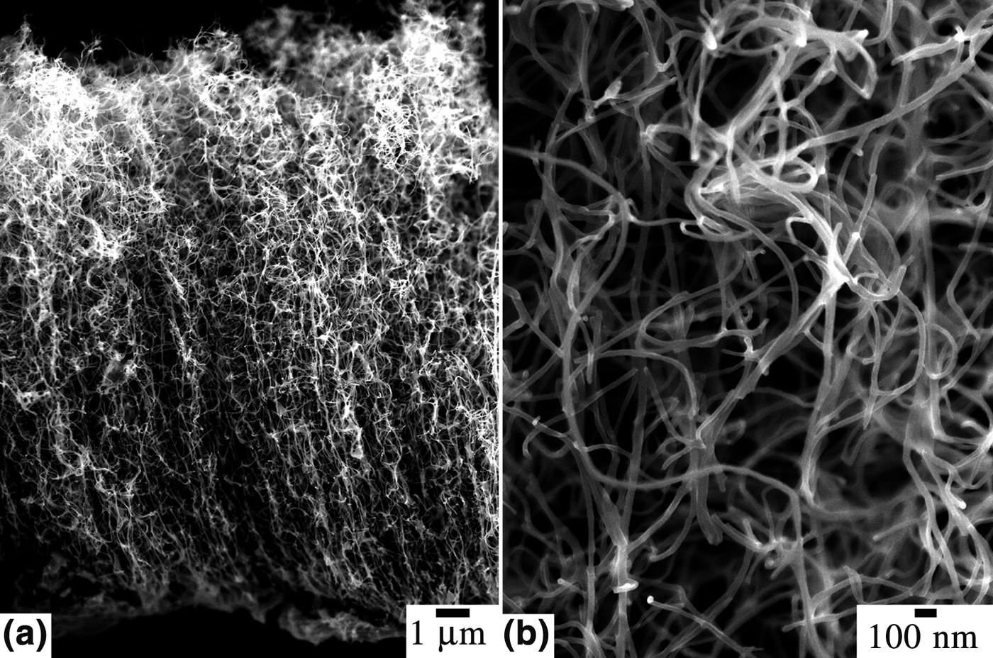
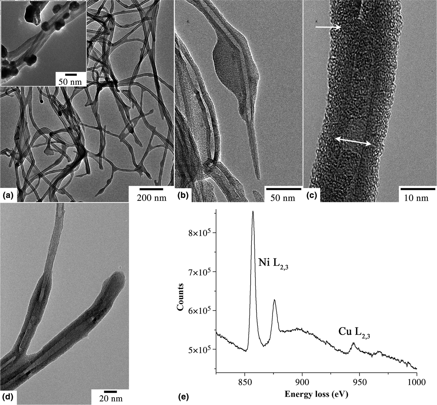
The morphology of the plated turf is shown in cross-section in Fig. 1(a). The thickness of this particular turf was about 15 µm. A higher magnification SEM image is displayed in Fig. 1(b), showing distinct tubes are still present. The electrodeposition parameters were adjusted and optimized so as to achieve uniform coatings. Best results (uniform and smooth coatings) were obtained for relatively low voltages, as illustrated in the TEM images shown in Figs. 2(a)–2(c) with 2.0 V for Ni and 0.7 V for Cu deposition. When using relatively high voltages, the metals deposited mostly on the top of the turfs in the form of large agglomerates, while at intermediate voltages individual grains nucleated directly on the CNTs. An example is shown in the inset of Fig. 2(a) for a CNT turf electroplated at 7.0 V for Ni and 0.8 V for Cu, with crystalline particles of the order of 50 nm. At low voltages, the coatings were found to be relatively uniform and conformal to the CNTs, with the presence of thicker regions in some sections of the CNTs creating small bulbs [e.g., image shown in Fig. 2(c) versus Fig. 2(b)]. The formation of a metallic “web” or fillet was often observed between adjacent CNTs, as shown in Fig. 2(d) recorded from a turf electroplated at 2.0 V for both Ni and Cu. Note that the turfs were observed as cross-sections, resulting in some minor blurring due to the instabilities (vibrations) because of the high aspect ratio of individual CNTs. At low deposition voltages, the coatings were amorphous; electron diffraction showed no evidence of distinct crystalline Cu or Ni, although high-resolution images [Fig. 2(c)] show that there are possibly small crystallites of metal in the coating. Their composition was confirmed to be Ni and Cu using electron energy-loss spectroscopy (EELS) as shown in the spectrum displayed in Fig. 2(e), recorded from a single-coated CNT (Ni −2.0 V for 1 min, Cu −2.0 V for 1 s, Ni −2.0 V for 1 min, and Cu −2.0 V for 1 s). Even for a two times 1 s electroplating of Cu, the core–shell composite contained Cu. X-ray energy-dispersive spectrometry (XEDS, data not shown here) also confirmed the presence of both Ni and Cu in the composites. There was no evidence of distinct bi-layer coatings, suggesting that either the limited amount of Cu deposited did not generate a complete layer, or that the system alloyed during deposition of the second metal.
SEM images recorded from an entire cross-section of a plated turf (a) and a higher magnification of the turf (b).

TEM images recorded from the composite foam fabricated at low electrodeposition voltages. Low magnification image (a) showing uniform coating of the CNTs. Higher electrodeposition voltages resulted in the formation of nanoparticles, as illustrated in the inset. At low electrodeposition voltages, the coatings were amorphous and sometimes not uniform in thickness resulting in the presence of bulbs, as shown in (b) versus the smooth coating in (c). The double-headed arrow in (c) denotes the width of the CNT, the single-headed arrow denotes a small crystalline region in the primarily amorphous coating. The necking of adjacent tubes by the metal coating occurred (d). EELS and XEDS (not shown here) demonstrated the presence of both Ni and Cu (e).
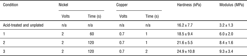
Once a conformal method of depositing metal was found, the layer thicknesses were varied by altering the plating time. Table I notes the conditions used for metal deposition, and the mechanical properties extracted from the nanoindentation experiments. The mechanical properties of the CNTs were examined in compression using a Hysitron Triboindenter 950 with a 100 µm diameter flat punch tip. The indentations were performed with a 10 s loading segment, a 20 s hold at maximum depth or load, and a 10 s unload. Typical indentation compression curves are shown in Fig. 3. Indentations were performed in depth control mode to verify the pull-off forces and ensure no significant changes in tip–sample adhesion occurred. Using a 100 µm diameter flat punch tip, tens of thousands of CNTs are contacted during loading, so the statistics are representative of the properties as a whole even though the total depth of penetration is relatively small.[Reference Qiu and Bahr20] As noted in Fig. 3, there is a minor amount of adhesion (of the order of 1–10 µN), but significantly less than what has been observed in other tests on pristine CNT arrays.[Reference Qiu, Bahr, Zbib, Bellou, Dj. Mesarovic, McClain, Hudson, Jiao, Kiener and Cordill21] Our compression tests only probed the top of the turf (Fig. 1), but future experiments are being planned to provide higher total strain conditions.
Typical load–depth curve for the pure turf and three composite foams (see details in Table I).
Plating conditions of the tested CNTs-metal foams, with average properties determined from nanoindentation. Between 14 and 17 tests were run on each sample.
Nanoindentation did not show any visible residual deformations on any of the tested turfs. For various plating times, the indentation hardness under load did not change significantly (≈50% increase for these conditions), while the modulus was much more sensitive to the amount of metal present in the coating, with a 300% increase in stiffness between the untreated and our thickest plating condition. The elastic recovery (from the maximum depth to the point at which there was no load on the tip during unloading) can be used as a first-order measurement of the elasticity, and varied from 85% for the acid-treated CNT turf, to 71%, 42%, and 52% for conditions 1, 2, and 3 respectively. Given that previous experiments on compression of CNTs arrays has shown that large elastic deformations are associated with tube–tube contacts which do not slide[Reference Qiu, Fowler, Jiao, Kiener and Bahr22] (i.e., contacts act like hinges); it is reasonable to assume that the additional metal deposition between tube–tube contacts further enhances the hinge-like behavior. Further work is needed to identify structures during deformation to verify this assumption (e.g., in situ experiments in the TEM).
In summary, we have shown that it is possible to coat CNTs arrays using a simple electroplating method. Two metals (Cu and Ni) were successfully deposited, producing an open cell foam core–shell composite structure exhibiting a high degree of elasticity in compression. Using CNTs or other carbon structures as templates, this method is amenable to design a wide range of mechanically robust metal nanostructures.
Acknowledgments
This work was supported in part through the National Science Foundation's CMMI program and the REU supplement program under grant number CMMI 0856436. Microscopy was made possible through the financial support of the NSF through their support of the Nanoscopy Facility, a user facility at UPR (NSF award 0701525). The assistance of Chloe Heinen, of Purdue University, in developing the acid pretreatment method is greatly appreciated.