I. INTRODUCTION
Ultra-wideband (UWB) communication systems have received significant attention from industry, media, and academia alike. The reason for all these excitements is that this technology promises to deliver both high data rate personal-area network wireless connectivity as well as longer-range, low data rate communication, with efficient utilization of scarce radio bandwidth in realistic multi-path environments, all while consuming very little power and silicon area. It is expected that UWB devices will provide low cost solutions that can satisfy the consumer's insatiable appetite for data rates spawning new consumer market segments.
Ultra wideband impulse radio (UWB-IR) makes use of ultra-short (<1 ns) base band pulses to communicate, thereby spreading the energy of the radio signal very thinly over extremely large frequency bandwidths [Reference Win and Scholtz1]. Given their very large bandwidth, the UWB-IR systems must share the spectrum with other users as well as with the existing communication systems. Even though UWB systems have high processing gain, and operate at very low power (due to regulations), they are highly susceptible to interference. And performance degradation of UWB communication due to interference from other co-existing services is a major issue. By using template waveforms derived from multi-carrier sinusoids at the transceiver, the interference power can to a large extent be mitigated [Reference Ohno and Ikegami2–Reference Lakshmanan and Nikookar5]. The template waveforms are constructed by representing the UWB transmission waveform with multi-carrier sinusoids and by selectively removing those sub-carriers whose spectral footprints fall near the interference spectrum. This way the UWB signal spectrum is sculpted to avoid the regions of interference. Through simulation studies it is proven that such an interference mitigation technique is effective, allowing for coexistence with different wideband systems.
However, these efforts employ a free space propagation model with no consideration for the frequency dependence of the UWB signal path loss. Since the UWB transmission signal occupies very wideband width, the path loss analysis for UWB communications should take into account frequency dependencies across the bandwidth of the signal. In this article, we extend the study by investigating the impact of waveform and template representation with multi-carrier method on the system performance under a frequency-dependent path loss model.
The paper is organized as follows. In section II, the major elements of the proposed system are explained. In section III, the UWB-IR transmission signal characteristics used in this article are presented. In section IV the construction of modified UWB-IR transmission waveform-based multi-carrier-type template representation for mitigation of interference on the UWB-IR communication system from co-existing sources is detailed. Section V lists the characteristics of potential interference sources such as IEEE 802.11a. In section VI the assumed propagation models are described. The performance measures used to gauge the impact of interference on UWB-IR transmission are defined in section VII. The simulation results are discussed in section VIII. The conclusions and inferences are drawn in section IX.
II. SYSTEM MODEL
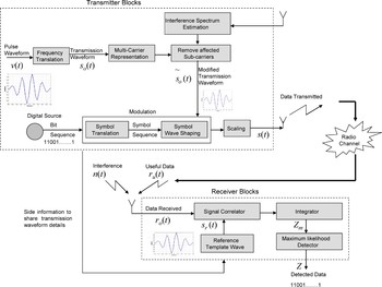
The system model of the proposed system is illustrated in Fig. 1. The major blocks in the transmitter include the radio spectrum estimator, transmission waveform shaper, and modulator. A signal correlator, integrator, and detector are the key elements of the receiver.
System model of the proposed system. The major blocks in the transmitter include the radio spectrum estimator, transmission waveform shaper, and modulator. The main receiver components are signal correlator, integrator, and detector.

At the transmitting end, first a data source generates an arbitrary stream of data derived from the source alphabet. The spectrum estimator gauges the channel and performs a radio scene analysis to estimate interference and detect spectrum holes. Meanwhile, an IR-UWB pulse waveform v(t) is frequency translated to obtain the UWB transmission waveform s o(t). Based on the spectrum estimates, the transmission waveform s o(t) is dynamically altered such that it has little or no energy in the interference domains and a modified transmission waveform  is constructed. The stream of data symbols is linearly modulated by the modified transmission waveform
 and scaled to the desired energy level to obtain the UWB signal s(t). The UWB transmission signal s(t) is then transmitted through to the channel.
Since the focus of this work is interference mitigation and transmission waveform shaping, to simplify the model the channel environment is assumed to be additive, white Gaussian (AWGN) with no multi-path effects or fading. Multiple access techniques like time hopping or direct sequencing are not adopted and only a single user case is assumed. Further, distortions such as ISI and ICI are not considered and the UWB radio signal sequence is taken to be composed of pulse waveforms that do not overlap in time.
At the receiver, the antenna picks the useful signal r u(t) corrupted by the interference signal n(t). The received signal r o(t) can be expressed as

where r u(t) is an attenuated and delayed variant of the transmitted signal s(t).
The received signal r o(t) is first correlated with a reference waveform s r(t). The reference waveform s r(t) is normally the same as the modified transmission waveform  . The correlated signal is then integrated to make a decision:
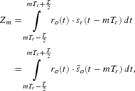
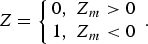
where Z m is the decision variable for the mth symbol, T r is the pulse repetition cycle, and T is the integral period. A decision on the transmitted data is arrived at using a maximum likelihood detector with the decision set Z given as
To enable the cognitive modules in the two ends to co-ordinate and act harmoniously, the transmitter constantly appraises the receiver on the characteristics of the transmission waveform by sending side information.
III. CHARACTERISTICS OF THE TRANSMISSION WAVEFORM
In this work, we consider the IR-UWB transmission pulse to be a Gaussian enveloped sinusoidal pulse that conforms to the FCC spectrum mask [Reference Ohno and Ikegami4–Reference Lakshmanan and Nikookar6]. The pulses are transmitted by the binary orthogonal pulse position modulation (PPM) and the transmitted signal s(t) is given as

where E TX is the transmitted energy per pulse, ɛ is the time shift introduced by PPM, and b m is either 0 (for bit 0) or 1 (for bit1). s o(t) is the frequency translated transmission waveform given by

with v(t) representing the energy normalized pulse waveform and f o the centre frequency. In this work the pulse shape s o(t) is taken to be a Gaussian enveloped sinusoidal pulse that conforms to the FCC spectrum mask. The pulse width is 1 ns and the centre frequency is considered to be 4.2 GHz. The pulse repetition time T r is fixed at 5 ns; therefore, the data rate is assumed to be 200 Mb/s. The modulation scheme used is binary orthogonal PPM. The PPM time shift ɛ is either 0 (bit 0) or 0. 5 ns (bit 1).
IV. MULTICARRIER REPRESENTATION OF TRANSMISSION WAVEFORM AND CONSTRUCTION OF MODIFIED TEMPLATE WAVEFORM
The modified template waveform is constructed by representing the transmission waveform as a multi-carrier-type template wave consisting of several sub-band pulses. When interferences exist, the modified template waveform is reconstructed by removing those sub-band pulses that are close to the interfering spectrum. This way it is possible to reduce the effect of the interferers.
The multi-carrier template representation of the transmission waveform is given as
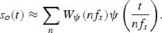
where nf s is the frequency of the nth sub-carrier and are transform coefficients of s o(t) given by
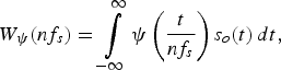
with

where v′(t) has the same form as v(t) but with an adaptable pulse width. Based on the spectrum estimates available, those sub-carriers whose frequency components fall in the neighborhood of the interference spectrum region are removed. The modified transmission waveform  is then reconstructed from the unaffected coefficients. The modified transmission waveform
 is given by

where m denotes the set of sub-carriers that fall in the region of interference spectrum and p denotes the set of all sub-carriers other than m.
Following notations of [Reference Ohno and Ikegami4], the signal s(t) is approximated by a set of 11 sub-carriers with a bandwidth of 200 MHz each, spanning from 3.2 to 5.2 GHz.
V. INTERFERENCE CHARACTERISTICS
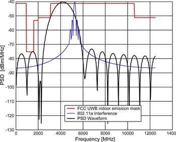
As interference a wideband IEEE802.11a source is considered. IEEE802.11a wireless systems are one of the most common sources of interference in UWB communication because their carrier frequency (around 5.25 GHz [7]) sits right in the middle of the UWB spectrum band of transmission (3.1–10.6 GHz). Therefore, as wideband interference an IEEE 802.11a source stationed at 5.25 GHz with a bandwidth of 200 MHz is considered [Reference Lakshmanan and Nikookar6]. An IEEE 802.11a system operates between 5.12 and 5.35 GHz and consists of eight carriers. Each carrier consists of 64 sub-carriers of bandwidth 312.5 kHz each. Of these 64 carriers, 52 carry data while the remaining 12 serve as pilot streams. Each sub-carrier is modulated by quaternary phase-shift keying and then packed into an OFDM symbol. The power spectral density (PSD) values of the transmitted waveform and the IEEE 802.11a interferer (normalized to level of the FCC mask) are as shown in Fig. 2.
PSD curves of the transmitted signal with 802.11a interference. The PSD curve of IEEE 802.11a has been normalized to the level of the FCC mask and the transmitted UWB waveform.

VI. PATH LOSS MODEL AND INTERFERENCE MEASURE
Path loss or path attenuation, by definition, is the attenuation undergone by an electromagnetic wave in transit between a transmitter and a receiver in a communication system. Path loss may be due to many effects such as free space path loss, reflection, refraction, diffraction, scattering, clutter, absorption from buildings, structures, or any other obstructions in the path. To characterize the UWB signal attenuation due to path loss, in this article, we consider the following two types of propagation models.
– A free space propagation model where the path loss depends on the transmitter to receiver distance.
– A frequency-dependent propagation model where the path loss depends on the transmitter to receiver distance as well as on the frequency.
A) Free space propagation model
The free space propagation model is used to characterize the signal attenuation for transmission of narrowband signals as well as for very simple cases where there is a direct path from the transmitter to the receiver with the absence of any substantial obstacles in the path of the signal. In this model, the received power P recv follows the inverse square law of the distance between the transceivers r and is given as
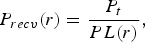
where P t is the transmitted power and PL(r) is the free space path loss. For omni-directional antennas with gains G t and G c, the free space path loss is given as [Reference Sheng, Orlik, Hiamovich, Cimini and Zhang8]
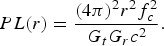
Here f c is the carrier frequency and c is the speed of light.
B) Frequency-dependent propagation model
UWB transmission occupies very wide frequency band, with the signal bandwidth exceeding the channel coherence bandwidth. Therefore, the frequency response of the channel is not flat, and the channel is frequency selective. Path loss analysis for UWB communications should therefore take into account frequency dependencies. As recommended by IEEE Standard [7] the path loss as a function of frequency and distance is taken to be the product of the terms

Denoting the frequency and distance dependence exponents as κ and γ, respectively, the frequency and distance dependence functions are given as

And the frequency-dependent path loss is computed to be

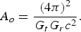
where A o is a normalization constant given as
And the received power P recv(r) is averaged over the whole frequency region (f L, f H), i.e.
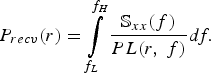
where  is the PSD of the transmitted signal. Combining (14) and (16) the received power is
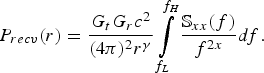
In these derivations a constant gain for transmitter and receiver antennas in the whole band has been assumed.
VII. PERFORMANCE MEASURE
A) Desired to undesired power ratio
To gauge the propagation loss and the effect of interference of co-existing users on UWB transmission, we define the performance measure (P desired /P interference), which is the ratio of desired signal power to the interferer (IEEE 802.11a) power.
1) FREE SPACE PROPAGATION MODEL
For this case, the Frii's transmission formula in free space is used. Assuming that the antenna parameters G t and G c are the same for both the UWB and interference setup, the ratio desired signal power to the interference power may be obtained by using (10) and (11)
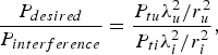
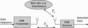
where P tu is the UWB transmission power based on the FCC emission limit. P ti is the transmission power of the interferer (IEEE 802.1la) available from the specifications of these systems [7]. The UWB wavelength λu is obtained from the geometrical mean between the UWB highest frequency and lowest frequency and λi is the interferer wavelength counted from the center frequency of the interferer. Parameters r u and r i are the distances between the UWB transmitter and the UWB receiver and the interferer and the UWB receiver, respectively (Fig. 3).
Block diagram of the simulation setup.

2) FREQUENCYDEPENDENT PROPAGATION MODEL
For this case, the UWB-IR received power is derived using (17), whereas the IEEE 802.11a received power is obtained from (10) and (11).
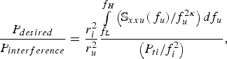
where  is the PSD of the transmitted UWB-IR signal, which is assumed to operate in the frequency band from f L to f H and f i is the interferer centre frequency.
B) Sensitivity
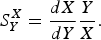
The sensitivity of the system is highly related to the path loss model of the channel. Therefore, the sensitivity of the path loss X to variations in path loss parameters Y (i.e.,  ) is evaluated using the following measure:
VIII. SIMULATION RESULTS
In this section, we analyze the performance of the modified template waveform based the on multi-carrier technique in the UWB transceiver for mitigation of interference from wideband sources like IEEE 802.11a. First the effect of the interfering sources on UWB communication is understood. Then the performance improvements brought about by using multi-carrier-type template in the transceiver is gauged. The template waveforms can be used at the transmitter alone or at the receiver alone or at both the transmitter and receiver ends. Next, we shall see how the combination of template waveforms affects the system performance. All these results are under the condition that the path loss model is frequency dependent.
To understand the performance of the UWB system, the bit-error rate (BER) versus the received energy within a single pulse to noise spectral density height (Ex/No) is plotted [Reference Di Benedetto and Giancola9]. The transmitter and the receiver use a modified template waveform. The template waveforms are obtained by a multi-carrier decomposition of the original signal with carriers in the region of the interference spectrum removed. The modulation scheme considered is binary orthogonal PPM.
A) Effect of interference on IR-UWB system performance
1) PERFORMANCE OF THE UWB SYSTEM UNDER IEEE 802.11A INTERFERENCE
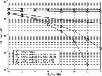
Figure 4 shows the BER performance curves of the UWB system in the presence of a wideband IEEE 802.11a co-existing user for various (P desired/P interference) ratios.
BER performance of UWB in the presence of AWGN and IEEE 802.11a interferer, for various (P desired /P interference). In the figure the (P desired /P interference) ratio is denoted as D/U.

From the figure it is evident that the presence of the IEEE 802.11a co-existing user affects the IR-UWB system performance. The performance worsens with decreasing (P desired / P interference) ratio. With decreasing (P desired /P interference) ratio, the interference to the UWB channel increases and hence the deterioration in performance.
It is clear from the results that the presence of co-existing users can cause impairments to the extent that normal system operation becomes impossible. There is therefore the need for a mechanism that can enable the systems to coexist. The multi-carrier template wave technique proposed above is one such mechanism.
In the following set of computer simulations the (P desired / P interference) ratio is taken to be −10 dB for the IEEE 802.11a interferer. This is roughly the case when the distance between the UWB transceivers and that between the UWB receiver and IEEE 802.11a transmitter are taken to be 1 and 30 m, respectively.
B) Influence of using modified template waveforms on enhancing system performance – improvements brought by representing the UWB waveform by a multi-carrier template and by selectively removing carriers affected by an IEEE 802.11a interferer
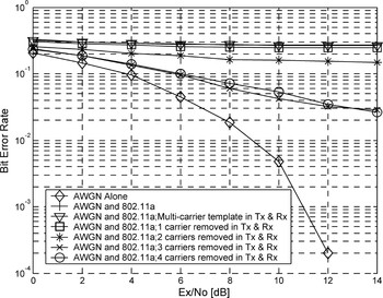
The BER performance curves of the UWB system in the presence of an IEEE 802.11a interferer is given in Fig. 5. Both the transmitter and receiver use multi-carrier-type templates. The plots illustrate the improvements in BER performance brought about by using multi-carrier-type template implementation at both the transmitter and receiver end and by selectively removing carriers in the neighborhood of the interferer spectrum. It is evident from the graphs that the template representation of the UWB transmission waveforms does have a positive effect on the system performance.
BER curves for system under IEEE 802.11a interference while using the multi-carrier template at both the transmitter and receiver ends. The notations Tx and Rx in the legend denote the transmitter and receiver, respectively. The sub-carriers from the template waveform are removed as follows – 1 carrier centered at 5.2 GHz, 2 carriers centered at 5.0 and 5.2 GHz, 3 carriers centered at 4.8, 5, and 5.2 GHz, 4 carriers centered at 4.6, 4.8, 5, and 5.2 GHz.

As more and more carriers are removed from the neighborhood of the interferer, the energy in the region of the coexisting interference source is reduced and the BER performance of the system improves. The best performance is obtained when using the template wave with three sub-carriers, centered at 4.8, 5, and 5.2 GHz, respectively, removed.
C) Effect of frequency dependency of the path loss of the UWB transmission signal on the system performance
The frequency dependence of the path loss is studied by varying κ and keeping the distance exponent γ (=2) constant.
1) SENSITIVITY OF PATH LOSS TO FREQUENCY DEPENDENCE EXPONENT κ
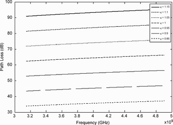
The path loss of the system varies as f 2κ and naturally is highly sensitive to variations in κ. This is illustrated in Fig. 6, which shows the variation of the path loss with frequency for various κ, as well as in Table 1, which gives the sensitivity of the path loss to changes in κ.
UWB path loss (in dB) for various frequency exponent κ.

Sensitivity  (linear values) of path loss (PL) to variations in κ. The path loss is averaged over all frequencies.

2) CO-EXISTENCE WITH IEEE 802.11A INTERFERENCE SOURCE UNDER A FREQUENCY-DEPENDENT PATH LOSS MODEL
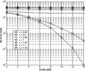
Figure 7 shows the BER performance curves of the UWB transmission system operating with a co-existing IEEE 802.11a user, for various κ (taken between 0.85 and 1.15). As the BER curves show the UWB system performance is not only affected by the presence of IEEE 802.11a source but also by κ. For small values of κ, the UWB path loss is small and the UWB received power is large enough to tolerate the presence of a co-existing IEEE 802.11a. In fact, for κ < 0.85 there is hardly any deterioration due to the IEEE 802.11a source on the UWB system performance. However, as κ increases, the path loss increases, resulting in a lower received power and hence a poorer BER system performance. The effect of changing κ can therefore be likened to making the UWB transceivers appear nearer (for κ < 1) or farther (for κ > 1) in comparison with the free space case condition (κ = 1). It is therefore of interest to gauge the extent to which the interference mitigation scheme can prove beneficial for varying κ, particularly for large κ.
BER curves for the system under IEEE 802.11a for various κ.

3) IMPACT OF FREQUENCY DEPENDENCE OF PATH LOSS MODEL ON INTERFERENCE MITIGATION STRATEGY FOR CO-EXISTENCE WITH THE IEEE 802.11A INTERFERENCE SOURCE
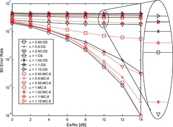
Figure 8 plots the BER performance curves of the UWB-IR system, using multi-carrier-type transmission waveforms constructed by removing three sub-carriers near the frequency spectrum of the IEEE 802.11a for κ between 0.85 and 1.15.
BER curves for the system under IEEE 802.11a interference for various κ. In the legend, OS stands for the original UWB signal and “MC-8” for multi-carrier representation with 3 of the 11 original sub-carriers removed. The three sub-carriers removed from the template waveform are centered at 4.8, 5, and 5.2 GHz.

As illustrated in the plots, using the template waveforms has a beneficial effect on the operation of the system for most values of κ. However, for larger values of κ (say κ ≥ 1.1) the path loss is so severe (Table 1) that the mitigation scheme is unable to recuperate the system performance. On the other hand, for small values of κ (say κ ≤ 0.85), the path loss is so less (Table 1) that the system is found to be capable of handling the interference on its own without a need for the interference mitigation strategy. The value of κ and hence the path loss thus serve as a limiting factor to the extent to which the template waveforms can be beneficial in handling interference. For the setup considered in this work, the optimum range for the mitigation scheme to be effective is 0.85 ≤ κ ≤ 1.05.
D) Effect of distance dependence of the path loss of the UWB transmission signal on the system performance
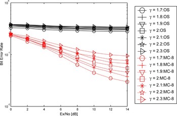
The distance dependencies are understood by varying the exponent γ while keeping κ (=1) constant. Figure 9 plots the BER performance curves of the UWB-IR system, using multi-carrier-type transmission waveforms constructed by removing three sub-carriers near the frequency spectrum of the IEEE 802.11a for various γ. As illustrated in the plots, using multi-carrier-type template waveforms has a beneficial effect on the operation of the system for all γ. Moreover, unlike variations in κ, the system performance is more robust to variations in γ.
BER curves for the system under IEEE 802.11a interference while using the multi-carrier template at the UWB transceiver for various γ. In the legend, OS stands for the original UWB signal and “MC-8” for multi-carrier representation with 3 of the 11 original sub-carriers removed. The three sub-carriers removed are centered at 4.8, 5, and 5.2 GHz.

To understand this, we must look at the sensitivity of the path loss with respect to variations in κ and γ, which can be easily derived from (14) and (20) to be 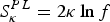 and
 , respectively. For the ranges considered in this work, this translates to
 , for 0.85 ≤ κ ≤ 1.15, and
 , for 1.7 ≤ γ ≤ 2.3. Now, the frequency ranges f of UWB signals are of the order of a few GHz, while the distance r is in the region of a few meters. Thus the path loss changes with variations to κ are far higher than that due to γ. This is corroborated by the figures in Table 2, which are much smaller than those shown in Table 1.
Sensitivity  (linear values) of path loss (PL) to variations in γ. The path loss is averaged over all frequencies.

E) Influence of waveform combination used in the transceiver on the system performance – comparison of improvements brought about by representing the UWB waveform by multi-carriers and by selectively removing affected carriers at the transmitter end alone, at the receiver end alone, and at both the transmitter and receiver ends, respectively, in the presence of IEEE 802.11a interference
The modified transmission waveforms can be used at the transmitter alone or at the receiver (as the reference waveform) alone or at both the transmitter and receiver ends. The transceiver waveform combinations influence the system performance in two ways.
1. Extent to which the transmitter–receiver template waveform combination neutralizes the corruption of the useful signal due to interference – the deterioration of the performance of the IR-UWB system due to IEEE 802.11a interference is due to corruption of the transmitted data.
At the receiver, a decision on the transmitted signal is arrived at by cross-correlating the received signal corrupted by interference with a reference waveform. An erroneous judgment is made when the information signal is garbled beyond recognition by the interference source. The idea of using a modified template waveform is to try and nullify the garbling effect of the interferer by not considering those sub-carriers whose spectral footprints lie near the region of the interference spectrum. With the energy removed when the reference waveform is multiplied and integrated, the interference is neutralized. It is therefore important that the reference signal at the receiver uses a modified template waveform. Whether the transmitter waveform will have role on the system performance depends on the second factor discussed below.
2. Sensitivity to loss of correlation between the transmitted template waveform and the reference waveform when they are different – it is important that the transmitted waveform and the reference waveform at the receiver are as closely matched as possible. This is important because during decision making the two signals are correlated to identify the transmitted information bit. However, during the construction of the modified template waveform when certain sub-carriers are removed, the waveform shape is altered. If one of the transmission or reference waveforms is based on the modified template waveform and the other based on the original signal, naturally the correlativity will be disturbed. But such loss of correlation can be tolerated when the alteration to the waveform property is less. Large changes to the waveform property, however, cannot be tolerated. Under such circumstances it is necessary that both the transmission and receiver reference waveforms use the modified template waveforms.
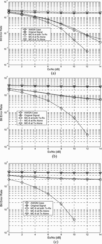
To understand this effect, we compare the system performance under interference while using multi-carrier template at the transmitter alone, receiver alone, and both transmitter and receiver, respectively. In these configurations it is assumed that information to construct the modified transmission waveform is available at the end where it is used, although it is not mandatory that it be available to the other end too. Figure 10 shows the corresponding BER performance curves.
BER curves for the system under IEEE 802.11a interference while using the multi-carrier template at the transmitter alone, receiver alone, and both the transmitter and receiver, respectively. The three sub-carriers removed from the template waveform are centered at 4.8, 5, and 5.2 GHz. κ considered are (a) 0.95, (b) 1, and (c) 1.05, respectively.

From the BER curves the following can be observed:
1) Effect of transmitter configuration – there is hardly any improvement in the performance of the system when the multi-carrier-type waveform is used at the transmitter alone.
2) Effect of receiver configuration – there are significant improvements when the modified transmission waveform is used either at the receiver alone or in both the transmitter and receiver ends.
3) Loss of correlation – when the transmission and reference waveforms are different, the loss in correlation between the waveforms is low and tolerable to the extent that it does not alter the system performance.
4) Varying κ changes the path loss and hence the system performance as described in the previous section. Other than that, the observations of (a), (b), and (c) are consistent for all κ. From these observations it may be inferred that while the modified waveform has a positive impact on the system performance, the improvements are purely due to such a representation in the receiver. Whether or not the transmitter uses the modified transmission waveform is of little interest.
IX. CONCLUSION
Degradation in the performance of the UWB wireless communication systems due to interference from co-existing services is an important issue. To address deterioration of performance due to wideband (IEEE 802.11a) interference on UWB communication, the use of multi-carrier-type transmission pulses and template waveforms is suggested. The template waveforms are constructed by representing the UWB transmission waveform with multi-carrier sinusoids and by selectively removing those sub-carriers whose spectral footprints fall near the interference spectrum. This way the UWB signal spectrum is shaped to evade regions of interference. Through simulation studies it is proven that such an interference mitigation technique is effective.
The novelty of the work vis-à-vis earlier works [Reference Ohno and Ikegami2–Reference Lakshmanan and Nikookar5] is in its treatment of both frequency and distance dependence of path loss model of UWB-IR transmission. With regard to the path loss model, inclusion of the frequency dependency influenced the performance of the system. The frequency and distance dependencies are studied by varying the exponents κ and γ, respectively. The path loss and hence the system performance were found to be highly sensitive to variations of κ. This in turn affected the efficacy of the proposed mitigation scheme. For low κ, the system was found to be stable enough and tolerated the presence of a co-existing interferer, thereby obviating the need for an interference mitigation scheme. And for high κ, the system performance was so severely affected that no improvement could be achieved through the interference reduction scheme. For the setup considered, the optimum range for which the proposed mitigation scheme is beneficial was found to be 0.85 ≤ κ≤ 1.05. With regard to the distance dependence, the system performance was lot more consistent and for almost all cases considered the interference mitigation scheme consistently proved to be ameliorative to the system performance.
 Madan Kumar Lakshmanan was born in Chennai, India, in 1979. He received his B.E. (with distinction) in electrical engineering from the University of Madras, Chennai, India, in 2000. In 2000, he joined the Indian Software firm, Polaris Software Labs Ltd., where he wrote software for Telecommunication applications. At Polaris, he was awarded the “On The Spot Of Excellence Award” for his efforts. In 2003, he moved to the Indian Institute of Technology-Madras, India, to lead a team of junior researchers to develop and establish a wireless communications network for rural connectivity. In 2004, he was granted the Royal Dutch/Shell Chevning scholarship to pursue a Masters program in Telecommunications at the Delft University of Technology (TU Delft). He completed his Masters (with CUM LAUDE) in 2006 and continued with his Ph.D. studies at TU Delft, where he is currently conducting research in the fields of wavelets, signal processing, and Wireless Communications at the International Research Center for Telecommunications Transmission and Radar (IRCTR). In December 2007 he won the “Best Student Paper” award at the 10th International Symposium on Wireless Personal Multimedia Communications, Jaipur, India.
 Homayoun Nikookar received his Ph.D. in electrical engineering from the Delft University of Technology (TUDelft), The Netherlands, in 1995. He is an Associate Professor at the International Research Centre for Telecommunications and Radar (IRCTR) of the Department of Electrical Engineering, Mathematics and Computer Science of TU Delft. He is also the leader of the Radio Advanced Technologies and Systems (RATS) program of the IRCTR. Dr. Nikookar has conducted research in many areas of wireless communications, including wireless channel modeling, UWB, MIMO, multicarrier transmission, wavelet-based OFDM, and cognitive radio. He is a senior member of the IEEE and the coauthor of the Book, Introduction to Ultra Wideband for Wireless Communications, Springer, 2008.