I. INTRODUCTION
Although the acid site on the external surface of zeolite is only 3–5% of total amount of acid, it has much impact on the catalytic performance. On the one hand, because the external surface of zeolite is fully accessible to all molecules, it will greatly weaken the shape selectivity of zeolite. On the other hand, the carbon deposition on the external surface caused by the acid site can increase the transport resistance of molecules in the catalytic reaction and even lead to a rapid deactivation of the catalyst in the applications of catalytic reaction.
Many studies have been conducted to modify zeolite, which gives rise to improving its surface property so as to obtain a reasonable distribution of acidity. Reference Ghorbanpour, Gumidyala, Grabow, Crossley and Rimer1–Reference Jia, Sun, Ye, Zou, Gu, Huang, Niu and Zhao7 The high acid density of zeolite catalysts can be alleviated by processes such as hydrothermal treatment in the presence of steam, Reference Al-Khattaf8–Reference Aramburo, Karwacki, Cubillas, Asahina, Matthijs de Winter, Drury, Buurmans, Stavitski, Mores, Daturi, Bazin, Dumas, Thibault-Starzyk, Post, Anderson, Terasaki and Weckhuysen13 acid leaching, Reference Qin, Lakiss, Gilson, Thomas, Goupil, Fernandez and Valtchev14,Reference Chandra Shekara, Jai Prakash and Bhat15 and extraction of aluminum from the framework of zeolite by reacting with SiCl4, Reference Kao and Chen16–Reference Triantafillidis, Vlessidis and Evmiridis18 EDTA, Reference Triantafillidis and Evmiridis17 or (NH4)2SiF6. Reference Kao and Chen16–Reference Triantafillidis, Vlessidis and Evmiridis18 The disadvantage of steaming is the partial amorphization of the zeolite framework. The relative crystallinity drops and the amount of the active sites decreases with the increasing severity of the treatment. Meanwhile, parts of the pores are filled with amorphous debris which leads to partial blocking of active centers. Reference van Donk, Janssen, Bitter and de Jong19 Elimination of blockage of active centers resulted from steaming is often conducted by a followed acid leaching treatment. Reference Lin, Fan, Shi, Liu and Bao20,Reference Abudawood, Alotaibi and Garforth21 To eliminate the external surface acid site of zeolite, a number of modification techniques have also been reported such as chemical vapor deposition Reference Hibino, Niwa and Murakami22,Reference Kim, Ishida, Okajima and Niwa23 and chemical liquid deposition of silicon alkoxides Reference Cejka, Zilkova, Wichterlova, Elder-Mirth and Lercher24,Reference Zheng, Tanaka, Jentys and Lercher25 and impregnation of phosphorous, MgO, or boron. Reference Chen, Kaeding and Dwyer26,Reference Kaeding, Chu, Young, Weinstein and Butter27 Although functionalization Reference Parker, de Angelis, Flego, Millini, Perego and Zanardi28 and passivating Reference Moreira, Herbst, de la Piscina, Fierro, Homs and Pereira29–Reference Bando, Koike, Kawai, Tateno, Oyama, Inada, Nomura and Asakura31 play an important role in controlling the zeolite selectivity because of partially killing the external active site, these methods have some drawbacks. For example, the species deposited on the external surface of the zeolite may reduce the effective diameter of the pore openings and even block the pores that would increase the diffusion resistance. Reference van Donk, Janssen, Bitter and de Jong19 In addition, some of the passivating agents may also bring side reaction. Reference Lutz, Toufar, Heidemann, Salman, Rüscher, Gesing, Buhl and Bertram32,Reference Féron, Gallezot and Bourgogne33
Overgrown Reference Goossens, Wouters, Grobet, Buschmann, Fiermans and Martens34–Reference Zheng, Zhang, Wang, Bai, Sun and Li39 or intergrown Reference Ohsuna, Terasaki, Nakagawa, Zones and Hiraga40 with a high-silica molecular sieve is also used to better the external surface acidity of zeolites catalysts. For example, MCM-41/FAU composite materials, which zeolite faujasite overgrown with a thin layer of mesoporous MCM-41, showed a higher conversion of heavy products compared to USY when tested in the catalytic cracking of vacuum gasoil Reference Kloetstra, Zandbergen, Jansen and van Bekkum41 due to the decreased external acidity density because of the formation of a thin layer of high-silica MCM-41. However, an interpenetration pore structure Reference Jia, Sun, Ye, Zou, Gu, Huang, Niu and Zhao7,Reference Qian, Du, Li, Si, Yang, Hu, Niu, Zhang, Xu, Tu, Tang and Zhao42,Reference Rollmann43 between the core and shell is very necessary in the abovementioned surface modification procedures because the interpenetration pore structure can overcome the drawback of functionalization and passivating, and guarantee that the reactant molecule can reach to the active center presented in the cores. For example, the micropore of USY zeolite crystal was found to be connected to the mesopore of SBA-15 shells, Reference Jia, Sun, Ye, Zou, Gu, Huang, Niu and Zhao7,Reference Qian, Du, Li, Si, Yang, Hu, Niu, Zhang, Xu, Tu, Tang and Zhao42 which offered the NiW-supported USY@SBA-15 catalyst an excellent catalytic performance in hydrocracking of heavy oil. Reference Jia, Sun, Ye, Zou, Gu, Huang, Niu and Zhao7
ZSM-5 zeolite is nowadays widely used as a catalyst, especially in the petroleum refining and petrochemical industries. Key factor for its performance is its shape selectivity; however, the acidity center on its external surface not only weakens the shape selectivity, but also results in a shortened catalyst life. As the Si/Al ratio of MFI zeolite can be adjusted in a large range, it provides the possibility for modifying and adjusting the external surface acidity of aluminum-rich ZSM-5 zeolite by overgrowing a different Si/Al ratio even a pure-silica MFI zeolite shell. Such as, MFI(core)/MFI(shell) composite zeolite composed of a low-silica ZSM-5 core coated by a high-silica ZSM-5 or pure-silica Silicalite-1 shell, was first reported by Rollmann Reference Rollmann43 in 1978. Kong et al. Reference Kong, Zou, Zheng, Qi and Fang44,Reference Zhou, Tong, Zou, Qi and Kong45 also demonstrated that the high-silica ZSM-5 shell could modify the external surface acidic properties of obtained core–shell zeolite–zeolite composite, which therefore inhibited the occurrences of side reactions on the external surface of the core–shell zeolite. A single crystal of ZSM-5 coated with Silicalite-1 was also reported by Lee et al. Reference Lee, Park and Lee46 Li et al. Reference Li, Wang, Hedlund, Creaser, Zhang, Zou and Bons47 investigated the crystalline structure of the dealuminated ZSM-5 crystals coated with Silicalite-1, and suggested that the Silicalite-1 might be grown epitaxially on the ZSM-5 core. Nishiyama et al. Reference Vu, Miyamoto, Nishiyama, Ichikawa, Egashira and Ueyama48,Reference Vu, Miyamoto, Nishiyama, Egashira and Ueyama49 reported that H-ZSM-5 crystals with various Si-to-Al ratios were coated with polycrystalline Silicalite-1 layers by a repeated hydrothermal synthesis. When applied to the alkylation of toluene with methanol, the Silicalite-1 coating significantly enhanced para-selectivity up to 99.9% under all reaction conditions. The Silicalite-1 coating on the H-ZSM-5 catalysts not only improved para-selectivity, but also prevented catalyst deactivation. However, in these reported results, the transfer phenomenon of alumina or/and silica species from the core to the shell, as well as the effect of SiO2/Al2O3 and thickness of the shell on the catalytic performances of the zeolite composite have never been investigated and reported.
In this study, zeolite–zeolite composite MMZas was prepared by using an alkali-treated ZSM-5 zeolite as a supporter for growing a high-silica MFI zeolites shell yielded from a pure-silica precursor. Acid sites associated with framework Al on exterior surfaces of ZSM-5 zeolite core are therefore passivated in different degrees by the epitaxial high-silicon MFI zeolites shell. Aluminum species were observed to transfer from the alumina-rich ZSM-5 zeolite core to the high-silica MFI zeolite shell, which offers the shell of the as-synthesized zeolite composite an adjustable Si/Al ratio. Influence of thickness and SiO2/Al2O3 ratio of the shell layer zeolite on the catalytic activity and deactivation behavior of the zeolite–zeolite composite catalyst was investigated during the methanol conversion into gasoline and diesel. In addition, the crystalline structure of the interface between the high-silica MFI-type shell and the alumina-rich ZSM-5 core was investigated carefully. The reasons for the high conversion of methanol and the high yield of diesel oil were discussed from the viewpoint of the structure of the core–shell zeolite–zeolite composite.
II. EXPERIMENTAL SECTION
A. Synthesis
Alkaline treatment of ZSM-5 core: alkaline treatment was carried out in 0.4 M aqueous NaOH (10 g of zeolite per 100 mL solution). In a typical experiment, the alkaline solution was stirred at 200 rpm and heated to 333 K, then template-free Na-formation ZSM-5 (SiO2/Al2O3 = 36, FRIPP, SINOPEC) powder was introduced and was kept stirring for 360 min, followed by quenching, filtration, extensive washing using distilled water, over night drying at 383 K, and denoted as ZSM-5(at).
MMZsa1 was prepared as following: First, Silicalite-1 zeolite precursor was prepared with a molar composition of the gel: 2.29 Na2O: 1.0 TPAOH: 15.0 SiO2: 2237 H2O. Typically, 16 g of tetrapropylammonium hydroxide and 3.6 g of sodium hydroxide were mixed in 25 g water to form a clear solution, then 60 g of silica sol (30 wt%) was slowly added to the solution with vigorous stirring. The mixture was stirred at room temperature for 2 h, then ZSM-5(at) was added to the mixture, and stirred for another 2 h at room temperature. The new mixture was then loaded into an autoclave for hydrothermal treatment at 413 K for 24 h under autogenous pressure. The as-synthesized solid product was recovered by filtration, washed with water, dried in air at 373 K overnight and denoted as MMZsa1, “a” stands for the added amount (g) of ZSM-5(at) zeolite powder.
For comparison, another zeolite–zeolite composite was prepared under the same procedures in which the Silicalite-1 zeolite precursor was prepared with the molar composition of the gel: 1 TPABr: 70 H2O: 1.5 Na2O: 9 SiO2, and denoted as MMZsa2, “a” stands for the added amount (g) of ZSM-5(at) zeolite powder.
All the as-synthesized samples were calcined in air at 823 K for 5 h, and the NH4 + form of the sample was obtained by performing an ion exchange with 0.5 M NH4NO3 solution (l:s = 10) twice at room temperature, for 2 h both times. The protonic form was then obtained by calcining the NH4 + form at 823 K for 5 h.
B. Characterization
The XRD patterns were recorded using a Rigaku Dmax/2500 (Rigaku Corporation, Tokyo, Japan) x-ray diffractometer, which used Ni-filtered Cu Kα radiation and was operated at 40 kV and 80 mA.
The crystal size and morphology of the as-synthesized samples were investigated on a JEOL/JSM-6700F (JEOL Ltd., Tokyo, Japan) scanning electron microscopy (SEM) coupled with an EDAX (EDAX Inc., Mahwah, NJ) energy-dispersive x-ray spectroscopy (EDS); crystal faces and interface structure were studied on a JEM-200CX (JEOL Ltd., Tokyo, Japan) transmission electron microscopy (TEM) coupled with a selected area electron diffraction (SAED).
The N2 adsorption at 77 K was performed in a Micromeritics ASAP2400 (Micromeritics Instrument Corporation, Norcross, GA) surface area analyzer to study the micro- and mesoporosity of the zeolite crystals. The mesopore size distribution was calculated using the Barret–Joyner–Halenda (BJH) pore size model, as applied to the adsorption branch of the isotherm. The microporous structure was obtained from the t-plot analysis of the adsorption branch of the isotherm.
XPS was conducted on a THERMOFISHER MULTILAB 2000 (Thermo Fisher Scientific, Inc., Waltham, MA) instrument.
The acid types (i.e., Brönsted or Lewis type) were recorded on an IR spectrometer by in situ pyridine adsorption. To measure pyridine adsorption, infrared spectra were obtained on a NICLOLET 6700 (Nicolet Instrument Inc., Madison, WI) spectrometer. ∼10 mg of sample was pressed into a self-supporting wafer that was about 10 mm in diameter. The wafer was first evacuated in situ in an IR cell at 300 °C for 2 h, and the IR spectra were recorded at room temperature. Pyridine was then introduced into the cell at room temperature until the saturated adsorption was reached. Finally, desorption of pyridine was performed step by step at increasing temperatures under 3 × 10⁻³ Pa and the spectra were recorded correspondingly.
Temperature-programmed desorption of ammonia (NH3-TPD) was carried out on a CHEMBET 3000 (Quantachrome Instruments, Boynton Beach, FL) apparatus equipped with a thermal conductivity detector (TCD). 70 mg of catalyst was loaded in a U-model quartz tube and supported by quartz wool. Then, it was treated at 550 °C for 3 h in a highly purified He (99.999%) flow. After cooling down to 120 °C, the sample was saturated with a NH3 (10%)/He gas mixture, followed by purging with the highly purified He for an hour at 120 °C. Then, the temperature was increased at a rate of 10 K/min in a highly purified He flow (80 mL/min), and desorption of NH3 was monitored. In this experiment, a water trap was set up between the sample and the TCD to avoid the influence of water.
C. Catalytic tests
The catalytic experiments were carried out on a standard micro-activity test unit (MAT). Prior to each experiment, the H-zeolite sample was pressed into a cylinder and then broken into 20–40 mesh particles and activated under the flowing N2 (50 mL/min) at 823 K for 2 h and then kept at desired reaction temperature. Methanol to gasoline reaction was carried out at 643 K with a WHSV of 8 h−1. Gas products were analyzed by an online gas chromatograph with an FID (Shimadzu Corp., Kyoto, Japan) detector and a GDX-101 column, while liquid products were analyzed by a gas chromatograph with an FID detector and a capillary column Rtx-1 (30 m × 0.25 mm × 0.25 µm).
III. RESULTS AND DISCUSSION
A. Synthesis and characterization
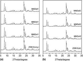
Figure 1 shows the XRD patterns of the starting zeolite ZSM-5(orig.), alkaline treated ZSM-5(at) and core–shell zeolite–zeolite composites MMZsa1 and MMZsa2. As compared with those of ZSM-5(orig.), the peaks at 7.90°, 8.75°, respectively assigned to [011] and [200] of ZSM-5(at), are distinctly weakened, indicating that poor crystallinity parts of ZSM-5 are selectively dissolved. Reference Ogura, Shinomiya, Tateno, Nara, Nomura, Kikuchi and Matsukata50 After coating by “Silicalite-1”, XRD patterns of MMZsa1 and MMZsa2 samples display the characterization diffraction peaks of pure MFI structure, and do not include diffraction peaks for impurities other than an MFI structure. It can be seen from Fig. 1 that the characteristic peaks at 7.90°, 8.75° and 23.00° of the zeolite–zeolite composites, especially, the MMZsa2 samples are further weakened in different degree as compared to those of the ZSM-5(at) zeolite materials, and the half-peak width corresponding to the peak at 8.75° of the zeolite–zeolite composites slightly widens, indicating that the decreased characteristic peaks at 7.90°, 8.75° and 23.00° of zeolite–zeolite composites may be caused by forming nano- or small-sized zeolite particles. Reference Xue, Ma, Zhang, Miao and Li51
XRD patterns of the as-synthesized zeolite–zeolite composites. (a) ZSM-5(orig.) and MMZsa1; (b) ZSM-5(at) and MMZsa2.

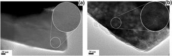
Figure 2 is the SEM images of the samples. It can be seen from Fig. 2(a) that the commercial ZSM-5 zeolite powder displays a clumped-together polycrystalline accumulation which coheres together by several slab-like particles with a size of approximately 2–3 µm. Alkali treatment had caused a significant change on the surface of the ZSM-5(at) as shown in Fig. 2(h), and many small holes were formed on its surface. TEM images (Fig. 3) show ZSM-5(orig.) zeolite a solid slab-like crystal, while ZSM-5(at) has a plenty of mesoporous channels. Direct evidence for the presence of mesopores with a fairly wide size of 5–50 nm in diameter is also provided by the TEM images as shown in Fig. 3(b).
SEM images of the samples. (a) The starting materials ZSM-5(orig.); (b) MMZs41; (c) MMZs61; (d) MMZs81; (e) MMZs42; (f) MMZs62; (g) MMZs82; (h) ZSM-5(at).

TEM images of the samples. (a) ZSM-5(orig.); (b) ZSM-5(at).

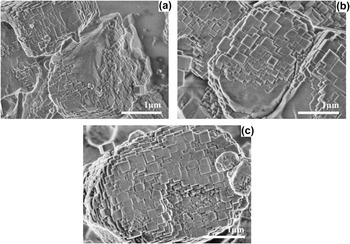
Zeolite–zeolite composites [Figs. 2(b)–2(g)] still keep the similar crystal morphology to the ZSM-5(orig.) and ZSM-5(at) zeolite crystals, while display a rather coarse external surfaces, which can be attributed to coating a layer of nano-sized “Silicalite-1” Reference Zhou, Tong, Zou, Qi and Kong45,Reference Vu, Miyamoto, Nishiyama, Ichikawa, Egashira and Ueyama48,Reference Vu, Miyamoto, Nishiyama, Egashira and Ueyama49 zeolite crystals on the ZSM-5(at) zeolite core. To further reveal the nature structure of as-synthesized zeolite–zeolite composites, samples MMZs81, MMZs61, and MMZs41 with the different core/precursor ratios were crushed by 25–30 Mpa pressure before observed by SEM. It can be seen from Fig. 4 that the core of the sample is partially exposed due to the partial damage of the shell composed of nano-sized “Silicalite-1” crystals, and the exposed core crystal still keeps the MFI-type characteristic which is very close to the morphology of zeolite ZSM-5 crystals as shown in Figs. 2(a) and 2(h). It can be seen from Fig. 4 that the shells of zeolite–zeolite composites are actually composed of multilayer nano-sized “Silicalite-1” crystals, and the shell layer thickness of MMZs81, MMZs61, and MMZs41 can be estimated at about 100–150 nm, 200–250 nm, and more than 300 nm, respectively. The abovementioned results confirm that the as-synthesized sample is a core–shell zeolite–zeolite composite with a ZSM-5 core and a polycrystalline shell composed of nano-sized “Silicalite-1” crystals.
SEM images of the zeolite–zeolite composites crashed by 25–30 MPa pressure before tested by SEM. (a) MMZs81; (b) MMZs61; (c) MMZs41.

It can be seen from Figs. 2(b)–2(d), and 4 that the coating layer of “Silicalite-1” on zeolite–zeolite composite MMZsa1 is composed of nano-sized particles with a size of about 100–200 nm, while the particles in the polycrystalline shell of composite MMZsa2 obtained by a different precursor yielding the shell exhibit a size of about 200–500 nm as shown in Figs. 2(e)–2(g). Figure 2 also reveals that the increased core/precursor ratio results in a perfect arrangement of the nano-sized “Silicalite-1” crystals in the shell. It seems as if MMZs81 and MMZs82 possess a mono-layer shell, and the nano-sized “Silicalite-1” crystals in the shells display a well-ordered arrangement on the external surface of the ZSM-5 zeolite cores, and are oriented in the same direction as the substrate ZSM-5 crystal surface. Reference Zhou, Tong, Zou, Qi and Kong45,Reference Vu, Miyamoto, Nishiyama, Ichikawa, Egashira and Ueyama48,Reference Vu, Miyamoto, Nishiyama, Egashira and Ueyama49 Nishiyama et al. Reference Vu, Miyamoto, Nishiyama, Ichikawa, Egashira and Ueyama48,Reference Vu, Miyamoto, Nishiyama, Egashira and Ueyama49 once reported that the “Silicalite-1” crystals, which overgrew on the ZSM-5 crystal surfaces, grew perpendicular to the a- and b-axes of the core crystals with the same orientation as the ZSM-5 zeolite substrate. With a decreased core/precursor ratio, the top layer of the shell of MMZs61 and MMZs62 seems to consist of random arrangement of nano-sized crystals. When the core/precursor ratio further decrease, some dissociative “Silicalite-1” zeolite crystals with the sizes of about 500–1000 nm are seen obviously in samples MMZs41 and MMZs42 as shown in Figs. 2(b) and 2(e). The less ZSM-5 substrates may not meet the space requirement for the overgrowth of the shells layer zeolite. That also indicates the shell layer zeolite can not grow in the manner of an unlimited growth. Reference Qian, Du, Li, Si, Yang, Hu, Niu, Zhang, Xu, Tu, Tang and Zhao42 It can be inferred from the overall perspective of the zeolite–zeolite composite MMZs81 and MMZs82 as shown in Fig. 5 that the dissociative “Silicalite-1” zeolite crystals significantly decrease with an enhanced core/precursor ratio.
Overall perspective of the zeolite–zeolite composite. (a) MMZs81; (b) MMZs61; (c) MMZs41; (d) MMZs82.

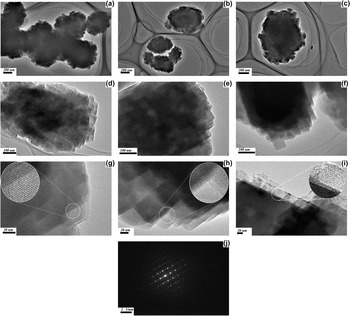
TEM image shown in Fig. 6 further reveal that both of MMZsa1 and MMZsa2 possess an obvious core–shell structure, and a decreased core/precursor ratio leads to an increased shell layer thickness. The core zeolite crystals are wrapped by the nano-sized Zeolite crystals, and no obvious interspace can be observed because of the same orientation growth of nano-sized crystals in the shells. Reference Vu, Miyamoto, Nishiyama, Ichikawa, Egashira and Ueyama48,Reference Vu, Miyamoto, Nishiyama, Egashira and Ueyama49 HRTEM images of zeolite–zeolite composite MMZs81 and MMZs82 [Figs. 6(g) and 6(h)] reveal the nano-sized crystals in the shell a uniform, well-ordered micropores channel arrays in large areas and no discontinuity or interrupt of the microporous channels can be observed, indicating a highly crystallization microstructure. Reference Liu, Ren, Shi, Zhang, Zhang, Tu and Zhao52 Figs. 6(g) and 6(h) also reveal that the microporous channels of the “Silicalite-1” layers formed at different positions on the ZSM-5 surface are parallel to each others. TEM image of MMZs81 [Fig. 6(i)] shows a crystalline structure of the interface between the ZSM-5 substrate and the “Silicalite-1” crystals in the polycrystalline shells. The microporous channels of the ZSM-5 cores and the “Silicalite-1” shells are in the same direction. No discontinuity of the microporous channels are observed between the ZSM-5 core and “Silicalite-1” crystals in the shells. The interface between the ZSM-5 substrate and the “Silicalite-1” is continuous without any misfits. In other words, the “Silicalite-1” crystals are grown epitaxially on the ZSM-5 substrate in the early stage of the Silicalite-1 growth, Reference Vu, Miyamoto, Nishiyama, Ichikawa, Egashira and Ueyama48 and the interface between “Silicalite-1” and ZSM-5 is coherent. Therefore, the “Silicalite-1” channels must be connected continuously to the ZSM-5 pores. Reference Vu, Miyamoto, Nishiyama, Ichikawa, Egashira and Ueyama48,Reference Vu, Miyamoto, Nishiyama, Egashira and Ueyama49 Similar epitaxial intergrowth of Silicalite-1 on ZSM-5 was reported by other researching group. Reference Zhou, Tong, Zou, Qi and Kong45 SAED pattern of the shell layer zeolites [Fig. 6(j)] further confirms that MFI crystallites are indeed formed in the shells. It can be inferred from Fig. 6(j) that the SAED pattern of the shell layer zeolites in MMZs81 displays a diffraction pattern very similar to a monocrystal. That can be caused by the same orientation growth of the nano-sized “Silicalite-1” crystals in the shells. The above-mentioned results also suggest that the shell composed of the nano-sized “Silicalite-1” zeolite crystals is compact and seamless due to the same orientation growth.
TEM images of the samples. (a) MMZs41; (b) MMZs61; (c) MMZs81; (d) MMZs42; (e) MMZs62; (f) MMZs82; (g) HRTEM of MMZs81; (h) HRTEM of MMZs82; (i) consecutive crystalline structure of the interface between the ZSM-5 cores and the “Silicalite-1” shells in zeolite–zeolite composite MMZs81; (j) SAED of shells in MMZs81.

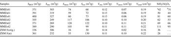
Chemical composition of a given zeolite is an important characteristic, which may be used to define its properties. Reference Zheng, Zeng, Zhang, Wang, Ma, Zhang, Sun and Li53 Although there is a difference by the different analysis technology, Elemental analysis obtained by XPS and EDS (in Table I) displays that shell layer zeolite is not “Silicalite-1”, but an MFI-type zeolite with the different Si/Al ratios. It can be seen from Table I that the SiO2/Al2O3 ratios (mol/mol, obtained by XPS) of the shell layer zeolites of MMZsa1 and MMZsa2, which were prepared by the similar procedure while with a different precursor yielding the shell, are about 42–81 and 62–111, respectively. The results obtained from Fig. 4 displays that the shell layer thickness of MMZs81 is about 100–150 nm, much thicker than that XPS can detect, namely, the SiO2/Al2O3 ratios obtained by XPS would be the real expression of the external surface chemical composition of the shell layer zeolites. As mentioned in experimental section, the precursors yielding the shells for either MMZsa1 or MMZsa2 did not include any aluminium species. The Elemental analysis results suggest that there is a transport course Reference Zheng, Zeng, Zhang, Wang, Ma, Zhang, Sun and Li53 of aluminum-species from the ZSM-5 zeolite cores to the shells. It can be seen from Table I that the decreased core/precursor ratio causes an increased SiO2/Al2O3 ratio of the shell. The SiO2/Al2O3 ratio obtained by XPS increases from 42 of MMZs81 to 50 of MMZs61, and to 81 of MMZs41; while the SiO2/Al2O3 of the shell of MMZsa2 increases from 62 of MMZs82 to 69 of MMZs62, and to 111 of MMZs42. The results also suggest that the transferred aluminum species from the core to the shell are mainly controlled by the added amounts of the core zeolite crystals and can be adjusted by controlling the core/precursor ratio.
Physical structrual properties of catalysts.

a Detected by XPS.
b Detected by EDS.
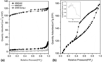
To further reveal the compactness of the shell in the core–shell zeolite–zeolite composite, ZSM-5(orig.), ZSM-5(at) and the noncalcined core–shell material MMZs81 and MMZs82, which possess the highest core/precursor ratio, were analyzed by N2 adsorption performed in a Micromeritics ASAP2400 surface area analyzer. As shown in Fig. 7(a), the adsorption–desorption of nitrogen on ZSM-5(orig.) zeolite is a type-I isotherm, indicating the presence of micropore only. Reference Xue, Ma, Zhang, Miao and Li51,Reference Zheng, Zeng, Zhang, Wang, Ma, Zhang, Sun and Li53 However, a curve combining type-I and type-IV isotherms is observed for the alkali treated ZSM-5(at) as shown in Fig. 7(b). Larger hysteresis loop occurred after p/p 0 ≈ 0.45 in the adsorption–desorption isotherm of ZSM-5(at), which indicates not only the presence of mesopores Reference Zhang, Ming, Ma, Zhang, Wang and Li54–Reference Wang, Yang, Tian, Xu, Yang, Wang, Yuan and Liu56 but a broad pore size distribution also. Reference Ogura, Shinomiya, Tateno, Nara, Nomura, Kikuchi and Matsukata50,Reference Groen, Peffer, Moulijn and Pérez-Ramírez57,Reference Jung, Park and Seo58 Pore size distribution [Fig. 7(b) (inset)] derived from the adsorption branch of the isotherm of ZSM-5(at) illustrates the existence of a mesopore structure with a broad pore size distribution ranging from 2 to 70 nm, which can be attributed to the extraction of silicon Reference Groen, Peffer, Moulijn and Pérez-Ramírez57–Reference Saxena, Viswanadham and Sharma59 from ZSM-5 zeolites crystals by the base in the synthesis solution. However, the BJH pore size distribution derived from the adsorption branch of the isotherm does not show a similar distribution in ZSM-5(orig.) as well as in the noncalcined core–shell material MMZs81 and MMZs82 (not shown here). The N2 adsorption–desorption data presented in Table I shows that the value of BET surface areas, microporous surface areas, and microporous volume of the ZSM-5(at) sample are 361 m2/g, 232 m2/g, and 0.22 cm3/g, respectively. In contrast, the isotherm of the noncalcined core–shell material is typical of a nonporous material with extremely low pore volume and surface area. The S BET of the noncalcined core–shell materials MMZs81 and MMZs82 are 13 m2/g and 21 m2/g, respectively. These results are a sound proof that only a limited number of shells contain pin holes via which the N2 molecules can penetrate the cores. Based on the differences between specific surface areas of the reference sample ZSM-5(at) and the corresponding noncalcined core–shell materials, the successful coverage of the core crystals is evaluated to be 94–97%. That is largely consistent with results obtained by TEM and SEM. Figs. 2 and 6 have confirmed that no intercrystalline mesoporous channels are practically formed in the shells because the nano-sized crystals in the shell grow in the same orientation to each other.
N2 adsorption–desorption. (a) N2 adsorption–desorption isotherms of ZSM-5(orig.), core–shell zeolite–zeolite composites MMZs81 and MMZs82 which comprising a non-calcined TPA-containing shell; (b) N2 adsorption–desorption isotherms and BJH pore size distribution curves (inset) of ZSM-5(at).

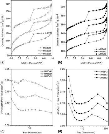
It can be seen from Figs. 8(a) and 8(b) that the curves combining type-I and type-IV isotherms are also observed for the calcined zeolite–zeolite composites MMZsa1 and MMZsa2. As shown in Figs. 8(c) and 8(d), the pore size distribution derived from the adsorption branch of the isotherms illustrates the existence of a mesopore structure with a broad pore size distribution ranging from 2 to 80 nm in MMZsa1 and 2–100 nm in MMZsa2, respectively, which are similar to that of ZSM-5(at). Further alkali etching on the ZSM-5(at) zeolite cores by the synthesis solution may also play a role in introducing the mesopores system into the zeolite–zeolite composites. The aforementioned results indicate that a hierarchical pore system has been introduced into the zeolite–zeolite composite, which has the regular micropores structures of MFI, and a meso-/and macroporous system existing in the cores. The regular micropore (<2 nm) and larger meso- or/and macropores (2–80 nm) simultaneously existing in the zeolite–zeolite composite lead to the combination of properties like shape selectivity and accessibility to restrict mass transfer limitations in the same material, that may offer the catalysts an important implication in different catalytic applications.
N2 adsorption–desorption isotherms and BJH pore size distribution curves of the samples. (a) and (c) isotherms and pore size distribution curves of MMZsa1, respectively; (b) and (d) isotherms and pore size distribution curves of MMZsa2.

Some N2 adsorption–desorption data are presented in Table I. As compared with ZSM-5(at), both of MMZsa1 and MMZsa2 exhibit higher value of BET surface areas, microporous surface areas and microporous volume, not only attributed to the formation of highly crystalline nano-sized MFI zeolites shell [Figs. 6(g) and 6(h)], also to the continuously connected channels between the ZSM-5 cores and the high-silica MFI zeolite shells Reference Kloetstra, Zandbergen, Jansen and van Bekkum41,Reference Vu, Miyamoto, Nishiyama, Ichikawa, Egashira and Ueyama48,Reference Vu, Miyamoto, Nishiyama, Egashira and Ueyama49 [Fig. 6(i)]. Obviously, the BET surface areas, microprous surface areas, and microporous volume of the core–shell composites are decided by both the ZSM-5 zeolite cores and the polycrystalline shells. Forming the high-crystalline MFI zeolites shell also offsets the effect of the alkali treated ZSM-5(at) zeolite cores on the microporous surface areas and volume as well as the BET surface areas in the zeolite–zeolite composites. However, as compared with the alkali treated ZSM-5(at) zeolite, all of the zeolite–zeolite composites display an enhanced S meso and a dramatically decreased S ext. The increased S meso can be ascribed to further alkaline etching Reference Groen, Peffer, Moulijn and Pérez-Ramírez57,Reference Saxena, Viswanadham and Sharma59 on ZSM-5(at) zeolite cores because of the higher treatment temperature, alkalinity and the longer treatment time during the preparation of the core–shell zeolite–zeolite composites. The formation of nano-sized MFI zeolites crystals unexpectedly brings the decreased S ext, which can be due to the nano-crystals constructing the successive, compact and seamless polycrystalline shells as observed by TEM, SEM, and the N2 adsorption results of the noncalcined core–shell material MMZs81 and MMZs82. The higher BET surface areas, microporous surface areas and microporous volume observed in the zeolite–zeolite composites also imply that the nano-sized MFI crystals in the shells are epitaxially grown on the surface of the ZSM-5 crystals and their pores must be directly connected to the pores of ZSM-5 substrates. Reference Miyamoto, Kamei, Nishiyama, Egashira and Ueyama36,Reference Okamoto and Osafune37,Reference Vu, Miyamoto, Nishiyama, Ichikawa, Egashira and Ueyama48,Reference Vu, Miyamoto, Nishiyama, Egashira and Ueyama49 That also further suggests that high-silica MFI-type zeolite in the shells forms an epitaxial layer on ZSM-5 cores without blocking the substrate pore openings.
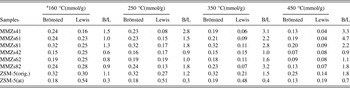
The acidic properties of the core–shell zeolite–zeolite composite were investigated by pyridine absorption, as measured by IR spectra. Brönsted-acid and Lewis-acid site amounts were calculated and given in Table II. It can be seen from Table II that an increased core/precursor ratio leads to an enhanced acid site. As compared with the alkali treated ZSM-5(at) zeolites, most of the zeolite–zeolite composites samples display enhanced Brönsted/Lewis acidity ratios, and the absolute Brönsted acidity are observed to be elevated in some of the zeolites–zeolite composites. That may provide an indirect proof that the transferred Al-species from the aluminum-rich ZSM-5 zeolite cores have entered into the frameworks of the shell layers zeolites. Table II also shows that the absolute acid content in MMZsa2 is lower than that in MMZsa1, which can be due to the different synthesis condition as shown in experiment section.
Acidity properties of the catalysts.

a C(Pyridine on B site) = 1.88IA(B)R2/W; C(Pyridine on L site) = 1.42IA(L)R2/W.
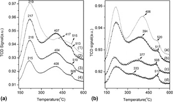
The removal of aluminium atoms from skeletal during the alkali treatment reduces the number of acid sites. Reference Ogura, Shinomiya, Tateno, Nara, Nomura, Kikuchi and Matsukata50,Reference Zhang, Ming, Ma, Zhang, Wang and Li54,Reference Wang, Li, Cho, Kung, Snyder and Fan55 The destruction of zeolite structure also causes the loss of strong acid sites. Reference Ogura, Shinomiya, Tateno, Nara, Nomura, Kikuchi and Matsukata50,Reference Wang, Li, Cho, Kung, Snyder and Fan55 It can be inferred from Fig. 9 that the decrease in the number of strong acid sites on ZSM-5(at) zeolite is clear when compared with the ZSM-5(orig.). Combining with the results as shown in Table II that the decreased strong acid sites on the MFI(at) zeolite may mainly be the Brönsted acid sites resulted from the destructed zeolites frameworks. Figure 9 suggests that the ZSM-5(at) just shows bevelment peaks at high temperature region, indicating that most of the strong acid sites disappear because of the destructed zeolite structure. Reference Ogura, Shinomiya, Tateno, Nara, Nomura, Kikuchi and Matsukata50 All of the zeolite–zeolite composites display rather different TPD profiles of ammonia from that of the alkali treated ZSM-5(at) sample. It can be seen from Fig. 9 that the alleviated peaks at the high temperature region on ZSM-5(at) have been significantly enhanced in the zeolite–zeolite composites because of the formation of the shells, indicating that the core–shell zeolite–zeolite composite has a rather different acid property as compared to the ZSM-5(at) core. The difference of acidity properties of the zeolite–zeolite composite from the ZSM-5(at) can be caused by the formed shells which have displayed the acidity properties in despite of yielded from a pure silica precursors. That further confirms that the aluminum species have partially transferred from the aluminum-rich ZSM-5(at) zeolite cores to the shells yielded from an aluminum-free precursor. It can be seen from Figs. 9(A) and 9(B) that the decreased (core/precursor ratio causes the reduced number of acid sites, especially the decreased media–strong acid sites. A relatively low acidity is found in MMZsa2 as compared with MMZsa1. That is largely in agreement with the results obtained in pyridine absorption.
NH3-TPD curves of the catalysts. (A) MMZsa1 and ZSM-5(at): (1): ZSM-5(at); (2): MMZs81; (3): MMZs61; (4): MMZs41; (B) MMZsa2 and ZSM-5(orig.): (a): ZSM-5(orig.); (b): MMZs82; (c): MMZs62; (d): MMZs42.

B. Effects of core–shell structure and tunable acidity
HZSM-5 is an advantaged catalyst in MTG (methanol to-gasoline) reaction. Reference Aguayo, Gayubo, Ereña, Vivanco and Bilbao60–Reference Bjørgen, Svelle, Joensen, Nerlov, Kolboe, Bonino, Palumbo, Bordiga and Olsbye63 However, this catalyst deactivates rapidly because of carbon deposition in the micropore channel during the methanol dehydration. The carbon deposition on the external surface or in the micropore can increase the transport resistance of reactant or product molecules, and even lead to a rapid deactivation of the catalyst, which hinders their practical applications. Reference Liu, Fan, Ma and Li64 As the Si/Al ratio of ZSM-5 zeolite can be adjusted in a large range, it provides the possibility for modifying and adjusting the external surface acidity of aluminum-rich ZSM-5 zeolite by growing high-silica or pure-silica MFI zeolite on the low-silica ZSM-5. Overgrowth with a high-silica or pure-silica shell can not only better the external surface acidic properties of aluminum-rich zeolite, also inhibit the side reactions, Reference Kong, Zou, Zheng, Qi and Fang44 which often occur in the chemical deposition Reference Hibino, Niwa and Murakami22–Reference Zheng, Tanaka, Jentys and Lercher25 as well as the impregnation, Reference Chen, Kaeding and Dwyer26,Reference Kaeding, Chu, Young, Weinstein and Butter27 functionalization, Reference Parker, de Angelis, Flego, Millini, Perego and Zanardi28 and passivating. Reference Moreira, Herbst, de la Piscina, Fierro, Homs and Pereira29–Reference Bando, Koike, Kawai, Tateno, Oyama, Inada, Nomura and Asakura31
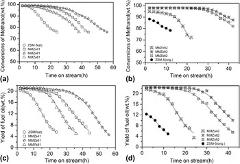
Catalytic performances of the core–shell zeolite–zeolite composites MMZsa1 and MMZsa2 in MTG were evaluated at 643 K in a standard micro-activity test unit (MAT), and compared with those of the references ZSM-5(orig.) and ZSM-5(at), and the results are displayed in Fig. 10. All the core–shell composite catalysts display efficient catalytic performances in the methanol dehydration reaction, and exhibit a significantly higher conversion rate, stability and selectivity toward the desired hydrocarbons than HZSM-5(at) and HZSM-5(orig.). Initial methanol conversion (2 h on the stream) on HZSM-5(orig.) presents 89%, however the conversion on the HZSM-5(at) is close to 99%. Within 10 h, HZSM-5(orig.) deactivates rapidly and the methanol conversion reduces sharply to lower than 80%. Whereas HZSM-5(at) keeps high methanol conversion for more than 10 h, and decreases to less than 80% after 20 h. With the increase of surface area of catalyst by the introduction of mesopores into the microporous zeolite, more active sites are exposed to reactants and diffusion path length is decreased obviously, Reference Xue, Ma, Zhang, Miao and Li51,Reference Zhang, Ming, Ma, Zhang, Wang and Li54,Reference Lee, Kim and Choi65 resulting in the higher conversion rate and longer catalyst life in the catalyst HZSM-5(at). Therefore, the introduction of mesopore would be an important factor to obtain an active and stable catalyst. Reference Xue, Ma, Zhang, Miao and Li51 In terms of yields, the fuel yield over HZSM-5(at) catalyst is significantly higher than that over HZSM-5(org.). The yield of fuel oil on HZSM-5(at) is up to 20% and keeps for 10h. However, the yield of fuel oil on the HZSM-5(orig.) catalyst is only 12% initially and then decreases to 5% after 12 h. Owing to the existence of intracrystalline mesopores, HZSM-5(at) offers a short diffusion path and a high diffusion rate. Reference Xue, Ma, Zhang, Miao and Li51,Reference Zhang, Ming, Ma, Zhang, Wang and Li54,Reference Lee, Kim and Choi65 The facts result in a high yield of fuel oil and lower cracking probability of long chain hydrocarbons to lighter paraffins, thus enhancing the resistance of the catalyst against deactivation.
Methanol dehydration to fuel oil. (a) Conversion of methanol over the catalysts MMZsa1 and ZSM-5(orig.); (b) conversion of methanol over the catalysts MMZsa2 and the alkali-treated ZSM-5(at); (c) yield of fuel oil over catalysts MMZsa1 and ZSM-5(orig.); (d) yield of fuel oil over catalysts MMZsa2 and the alkali-treated ZSM-5(at).

Because the acid sites associated with framework Al on exterior surfaces of the hierarchical ZSM-5(at) zeolite cores are partly passivated by the MFI zeolite shells with an adjustable thickness and SiO2/Al2O3 ratio, which may make the as-synthesized zeolite–zeolite composite a potential and high-efficiency catalyst for methanol dehydration to gasoline–diesel oil. It can be seen from Fig. 10 that the formation of the high-silicon MFI zeolite shell affords the core–shell zeolite–zeolite composite MMZsa catalyst a promoted catalysis performance with a dramatically enhanced stability and a higher average yield of fuel oil in the methanol dehydration reaction as compared with the references catalysts ZSM-5(at). Although the acid sites on the external surface of HZSM-5 is only 3–5% of total amount of acid, it has much impact on the catalytic performances. The external surface of zeolite is fully accessible to all molecules, and the carbon deposition on the external surface caused by the acid sites can increase the transport resistance of molecules in the catalytic reaction and even lead to a rapid deactivation of the catalyst in the applications of catalytic reaction. Overgrown with a high-silica MFI zeolite can effectively adjust the acid density of the catalyst, which will alleviate the carbon deposition on the pore opens. As a consequence, that affords the catalyst an excellent catalytic performance. As compared with MMZs81, MMZs61 catalyst displays an enhanced stability because of the decreased acid site density in the external surface of the catalyst. Table I suggests that a decreased ratio of core/precursor results in an alleviated surface acid site density because of an increased Si/Al ratio in the shell of the zeolite–zeolite composite, that contributes to depressing the carbon deposition on the external surface of the catalyst. Reference Vu, Miyamoto, Nishiyama, Ichikawa, Egashira and Ueyama48,Reference Vu, Miyamoto, Nishiyama, Egashira and Ueyama49,Reference Liu, Fan, Ma and Li64 However, MMZs41 exhibits a weakened catalytic performance as compared to MMZs61. That may be ascribed to the increased diffusion resistance resulted from the thicker shell layer. Figure 4 reveals that the decreased core/precursor ratio leads to an increased shell thickness, the highest diffusion resistance can therefore be deduced to occur in MMZs41 catalyst due to the longest diffusion length because of the thickest shell layer. For the series of MMZsa2 catalysts, MMZs42 behaves as a poor catalytic performance with a decreased initial conversion of methanol and a lower stability during the methanol dehydration reaction, which can not only be attributed to the increased diffusion resistance because of the increased shell layer thickness, but also be ascribed to the excessively weakened acidity. Dramatically decreased core/precursor ratio results in a poor acidity as detected by in situ IR spectra of pyridine and NH3-TPD, which may play an important role in weakening the catalytic performances of MMZs42 catalyst during the dehydration of methanol to gasoline-diesel oil. Obviously, not only does the Si/Al ratio of the shell layer zeolite in the zeolite–zeolite composites, but the diffusion length of the catalysts plays an important role in the catalytic performances also. Reference Xue, Ma, Zhang, Miao and Li51,Reference Zheng, Zeng, Zhang, Wang, Ma, Zhang, Sun and Li53
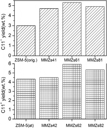
As compared with ZSM-5(orig.) and ZSM-5(at), the higher average yields of fuel oil over the core–shell composite MMZsa catalysts as shown in Fig. 11, Figs. 10(c) and 10(d) can be ascribed to the special core–shell structure as well as the created hierarchical pore system and the weakened strong acid sites as detected by NH3-TPD. The mesoporous structure in the zeolite catalysts decreases the probability of product cracking and coking, therefore, not only leads to a longer catalytic life, but a higher yield of gasoline during the conversion of methanol to gasoline Reference Liu, Fan, Ma and Li64 ; the weakened strong acid site depresses the deposit of coking Reference Li, Wang, Jia, Xi, Chen, Zhu and Hu66,Reference Fan, Tian, Su, Yuan, Wang, Wang, Yang, Wang, Xu and Liu67 by avoiding the formed long-chain fuel oil molecules from being further cracked. That also contributes to enhancing the yield of fuel oil; the special core–shell structure with an alumina-rich ZSM-5 core and high-silica MFI zeolite shell contributes to depressing the coking deposit on the external surface of the catalysts. The passivated external surface modified by the high-silica shell as well as the created hierarchical pore system and the weakened strong acid sites also result in the core–shell composite catalyst a higher average yield of C11+ in the fuel oil during the time on stream as shown in Fig. 11.
Average yield of C11+ in the fuel oil during the time on stream.

IV. CONCLUSIONS
Core–shell zeolite–zeolite composites MMZas were successfully prepared by using an alumina-rich commercial ZSM-5 zeolite as a substrate for supporting the epitaxial growth of the nano-sized MFI zeolite crystals, in which the acid sites associated with framework Al on exterior surface of ZSM-5 zeolite core were passivated by an epitaxial high-silicon ZSM-5 zeolites shell with a tunable thickness. XPS and EDS analysis confirmed that aluminum species had transferred from the low-silicon ZSM-5 zeolite core to the polycrystal shell yielded from the pure-silicon precursor, and the SiO2/Al2O3 in the shell can be adjusted by controlling the ratio of the core/precursor. TEM and N2 adsorption-desorption studies revealed that high-silicon ZSM-5 zeolite shell forms an epitaxial layer on ZSM-5 crystal without blocking pore openings. N2 adsorption–desorption tested on the core–shell zeolite–zeolite composite, which microporous channels in the shell was still filled with TPA+, revealed the presence of a continuous and compact shell. SEM and transmission electron microscopy were used in combination to confirm that the shell thickness can be tailored with nanometer resolution (e.g., 100–300 nm). IR-Pydrine combined with NH3-TPD measurements revealed the transferred aluminum from the aluminum-rich cores to the shells had entered the frameworks of the nano-sized zeolite crystals in the shells, and acid properties of the core–shell zeolite–zeolite composites can be adjusted by controlling the growth of the shell layers. As compared with the starting low-silicon ZSM-5(at) using as the core in the composites, the core–shell composite catalysts displayed an excellent catalysis performance when tested during the methanol dehydration to fuel oil, and the zeolite–zeolite composites with different shell layers thickness or Si/Al ratios exhibited the different yields of fuel oil and stabilities. The synthesis of MMZas may offer a pathway for tailoring the physicochemical properties of MFI-type materials, notably in the area of catalysis, where surface passivation can enhance product selectivity or/and stability without sacrificing catalyst activity. The method described herein may prove to be a general platform for zeolite core–shell design with potentially broader applicability to other porous materials.
ACKNOWLEDGMENTS
This work is supported by the National Natural Science Foundation of China-SinoPEC (No. U1463209), the National Natural Science Foundation of China (Nos. 21371129; 21376157; 51272169).